THE THERMOECONOMICS OF ENERGY CONVERSIONS
Elsevier Internet H o m e p a g e - http://www.elsevier.com Consult the Elsevier homepage for full catalogue information on all books, journals and electronic products and services. Elsevier Titles of Related Interest
ARENTSEN & KUNNEKE National Reforms in European Gas ISBN: 0-08-043687-0 MIDTTUN European Electricity Systems in Transition ISBN: 0-08-042994-7 MIDTTUN European Energy Industry Business Strategies ISBN: 0-08-043631-5 WANG China's Oil Industry and Market ISBN: 0-08-043005-8 Related Journals:
A sample journal issue is available online by visiting the homepage of the journal (homepage details at the top of this page). Free specimen copy gladly sent on request. Elsevier Ltd, The Boulevard, Langford Lane, Kidlington, Oxford, OX5 1GB, UK Applied Energy Applied Thermal Engineering Energy Energy Conversion and Management Energy Economics Energy Policy Experimental Thermal and Fluid Science International Communications in Heat and Mass Transfer International Journal of Heat and Fluid Transfer International Journal of Heat and Mass Transfer International Journal of Thermal Sciences To c o n t a c t the Publisher
Elsevier welcomes enquiries concerning publishing proposals: books, journal special issues, conference proceedings, etc. All formats and media can be considered. Should you have a publishing proposal you wish to discuss, please contact, without obligation, the Publishing Editor responsible for Elsevier's Energy programme: Tony Roche Publishing Editor Elsevier Ltd The Boulevard, Langford Lane Kidlington, Oxford OX5 1GB, UK
Phone: Fax: E-mail:
-t-44 1865 843887 -t-44 1865 843931
[email protected]
General enquiries, including placing orders, should be directed to Elsevier's Regional Sales Offices - please access the Elsevier homepage for full contact details (homepage details at the top of this page).
THE THERMOECONOMICS OF ENERGY CONVERSIONS Yehia M. EI-Sayed
Advanced Energy Systems Analysis, California, USA
2003
ELSEVIER A m s t e r d a m . B o s t o n . H e i d e l b e r g . L o n d o n . New Y o r k . O x f o r d . Paris San Diego 9San Francisco 9Singapore 9S y d n e y . Tokyo
ELSEVIER Ltd The Boulevard, Langford Lane Kidlington, Oxford OX5 1GB, UK 92003 Elsevier Ltd. All rights reserved. This work is protected under copyright by Elsevier and the following terms and conditions apply to its use: Photocopying single photocopies of single chapters may be made for personal use as allowed by national copyright laws. Permission of the Publisher and payment of a fee is required for all other photocopying, including multiple or systematic copying, copying for advertising or promotional purposes, resale, and all forms of document delivery. Special rates are available for educational institutions that wish to make photocopies for non-profit educational classroom use. Permissions may be sought directly from Elsevier via their homepage (http://www. elsevier.corn) by selecting 'Customer Support' and then 'Permissions'. Alternatively you can send e-mail to:
[email protected], or fax to (+44) 1865 853333. In the USA, users may clear permissions and make payments through the Copyright Clearance Center, Inc., 222 Rosewood Drive, Danvers, MA 01923, USA; phone: (+1) (978) 7508400, fax: (+1) (978) 7504744, and in the UK through the Copyright Licensing Agency Rapid Clearance Service (CLARCS), 90 Tottenham Court Road, London WlP 0LP, UK; phone: (+44) 207 631 5555; fax: (+44) 207 631 5500. Other countries may have a local reprographic rights agency for payments. Derivative Works Tables of contents may be reproduced for internal circulation, but permission of Elsevier is required for external resale or distribution of such material. Permission of the Publisher is required for all other derivative works, including compilations and translations. Electronic Storage or Usage Permission of the Publisher is required to store or use electronically any material contained in this work, including any chapter or part of a chapter. Except as outlined above, no part of this work may be reproduced, stored in a retrieval system or transmitted in any form or by any means, electronic, mechanical, photocopying, recording or otherwise, without prior written permission of the Publisher. Address permissions requests to: Elsevier Global Rights Department, at the mail, fax and e-mail addresses noted above. Notice No responsibility is assumed by the Publisher for any injury and/or damage to persons or property as a matter of products liability, negligence or otherwise, or from any use or operation of any methods, products, instructions or ideas contained in the material herein. Because of rapid advances in the medical sciences, in particular, independent verification of diagnoses and drug dosages should be made. First edition 2003
Library of Congress Cataloging in Publication Data A catalog record from the Library of Congress has been applied for. British Library Cataloguing in Publication Data A catalogue record from the British Library has been applied for.
ISBN: 0-08-044270-6 (~ The paper used in this publication meets the requirements of ANSI/NISO Z39.48-1992 (Permanence of Paper). Printed in Hungary.
Contents Preface Introduction 1.1 The Emerging Concerns 1.2 The Complexity of the Design Space 1.3 The Level of Details of a System Description 1.4 The Interaction of Energy and Materials Requirements 1.5 The History of Thermoeconomics Development 1.6 The Question Posed for Thermoeconomic Analysis 1.7 The Importance of an Integrated Database 1.8 The Main Pillars of Thermoeconomic Analysis 1.9 General References
1 1 2 3 3 4 5
5 6 6
Improved Thermodynamic Analysis
11
2.1 The Exergy Function 2.2 The Thermodynamic Analysis of a System in the Steady State 2.3 Tutorial 2.4 References
12 17 20 29
Improved Costing Analysis 3.1 The Objective Function as a Cost Function 3.2 Making and Operating Resources of an Energy-Conversion Device 3.3 The Quantification of the Making and Operating Resources for a Device 3.4 Making and Operating Resources of a System of Devices 3.5 The Cost Indices C F , {cZi},and {cai} 3.6 Combining Second-Law and Costing Analyses (Thermoeconomic Analysis) 3.7 Tutorial 3.8 Selected References
31 31
Enhanced System Optimization 4.1 A Two-Level Decomposition Strategy 4.2 Decomposition at the Discipline Level 4.3 Decomposition at the Device Level 4.4 More on the Objective Function and on Decomposition 4.5 Programming Thermoeconomic Analysis 4.6 Tutorial 4.7 Selected References
49
31 32 34 35 35 37 48
49 49 52 58 63 67 80
vi
The Thermoeconomics of Energy Conversions
The Manipulation of the Design Models of Devices Multidisciplinary Problems in General The Communication Between the Disciplines of Thermodynamics and Design 5.3 A Heat Exchange Device 5.4 Tutorial 5.5 Selected References
83 83
Off-Design Performance Due to Load Variation Managing the Inefficiency of Variable-Load Operation Predicting the Part-Load Performance of a System of Devices 6.3 Handling the System-Design of Variable-Load Problems 6.4 Optimal Operation of a Facility of Systems of Same Product 6.5 Tutorial 6.6 Selected References
97 97
105 107 109
7.1 7.2 7.3 7.4
Application Examples Time-Independent Production Time-Dependent Production Closing Remarks Selected References
111 111 123 136 137
8.1 8.2 8.3
Software, Analyzed Systems and their Flow Diagrams: Contents of the Compact Disc Brief Description of the Six Executable Tools The Analyzed Systems and Their Flow Diagrams
139 139 140 151
Appendices
199
5.1 5.2
6.1 6.2
9
83 84 91 94
99 99
Appendix 9.1
Some Useful Forms of the Flow Exergy
199
Appendix 9.2
Thermodynamic and Design Models
205
Appendix 9.3
Capital and Performance Equations
211
Appendix 9.4
Refreshing Basic Engineering Material
217
Appendix 9.5
Selected General Properties
231
Appendix 9.6
A Selected Compilation of Heat Transfer Film Coefficients and Friction Factors
235
Glossary
249
Appendix 9.7
Contents
vii
Appendix 9.8
Nomenclature
253
Appendix 9.9
Constants and Conversion Factors
257
Subject Index
261
This Page Intentionally Left Blank
Preface Dedicated to future generations of scientists and engineers willing to develop efficient energy conversion systems for the benefit of human civilization and the environment The increasing demand for power and material products by current energy conversion technologies using fossil and nuclear fuels on one hand and the adverse impact on the environment on the other hand, did create an energy conversion crisis that is going to stay for decades to come. The increasing demand is driven by the increase of world population and a rising standard of living. The adverse impact is emissions, waste disposal, and the signs of global warming. The long-lasting energy conversion crisis is due to the absence of alternative energy resources and conversion technologies that are both friendly to the environment and economically competitive to the present ones. Until emerging or new competitive technologies become available, the cost-effective increase of the conversion efficiencies of current technologies is the only option to reduce the impact of the crisis. Directions of raising system efficiency are well established thermodynamically but not the directions of their cost effectiveness. The book surveys briefly the recently developed methodologies that reveal the cost effectiveness of sought energy-resource-saving ideas by design. The book then focuses on one methodology that became known as thermoeconomics. The theory is presented. Tutorial and application examples are given. The examples deal with both systemdesign analysis and the design analysis of energy conversion devices. A number of executable programs set the stage for the analyses and provide the results. The programs are described and samples of the source code in "BASIC" are included. All programs are available on one compact disc. The goal of the book is a set of energy analysis tools that is useful, concise and easy to understand and apply. The book is an outcome of more than a 20-year development of thermoeconomics. The book will be useful to both a system-designer and a device-designer. It will be particularly useful to students. They will be prepared to reshape the traditional energy system design during their active career into a more powerful optimal-design methodology. Thermoeconomics launches an intensive analysis dose on the design concepts of energy conversion systems for the purpose of revealing opportunities of fuel and cost savings. The description of system configurations is modular, process-oriented, and is easy to expand or modify. The approach to the solution of the modeling equations of a configuration is numerical. Chapter 1 presents an overview of the building blocks of the design analysis of systems that use or produce useful forms of energy and the methodologies of handling them. The chapter ends with a representative sample of current methodologies of optimal system design and selected references as a guide to further study. For seeking transparency for higher system efficiency, the thermodynamic analysis is extended to include the second law of thermodynamics quantitatively. The extension
x
The Thermoeconomics of Energy Conversions
is known as exergy analysis or second-law analysis. Exergy analysis permits assigning a consumption of the input energy resource to each process in a system. This reveals how the input energy resource is utilized throughout a system. Chapter 2 deals with secondlaw analysis and demonstrates the transparency for higher efficiency. For seeking lower product cost, a rational basis for cost analysis is first sought. Cost unlike efficiency is multidisciplinary. The main participating disciplines beside thermodynamics are design, manufacture, and economics. A communication protocol among the participating disciplines is essential to establish the sought rational basis. An interdisciplinary communication is formulated mathematically. The cost function of a device, based on the formulated communication, is named costing equation. Mathematically formulated communication is useful to multidisciplinary problems in general and not limited to costing equations. Chapter 3 addresses a rational basis for costing energy conversion devices for the purpose of optimal system design. The exergy analysis of Chapter 2 and the costing equations of Chapter 3 are combined to establish "thermoeconomics" which may simply be called the economics of lost work or the economics of exergy destructions. The complexity of design-point optimization of a considered system configuration is managed by a two-level decomposition strategy: at the discipline level and at the device level. Costing equations decompose the system at the discipline level. The principle of matched objectives of the devices and their system decomposes the system at the device level. The role of the assigned fuel resource consumption to each process in the system is central in creating the match. Expressing costing equations in terms of thermodynamic variables allows the optimization of a system configuration to be performed within the thermodynamic domain where the system is born. Chapter 4 deals with this enhancement of system optimization. Chapter 5 emphasizes the importance of the design models of energy conversion devices as rich resources for predicting both their costs, their performances and overall performance of their system. The complexity of off-design performance is addressed in Chapter 6. An attempt to relate the optimal design of a variable-load system to a corresponding base-load optimal design is presented. A variable-load design problem, in certain situations, may be reduced to a minimized cost base-load design and a superimposed minimized off-design cost penalty. Chapter 7 deals with application problems. The problems cover power generation and co-generation. Co-generation focuses on power and desalinated water as well as power and heat for refrigeration and air conditioning. Systems of time-independent production (base-load design) are first considered followed by variable-load systems. Four journeys of base-load optimal system design are conducted, one for a gas turbine power system, one for a seawater distillation-process system and two exploring examples of emerging technologies. The results are summarized and compared on cost-efficiency coordinates. The prediction of the part-load performance of a system is then demonstrated on a simple combined power cycle. The fuel and the cost penalties of time-dependent production are then considered for two gas-turbine systems co-generating power, heating and cooling of different load profiles with and without dependence on the power grid. Chapter 8 deals with the software of the accompanying compact disc. The software consists of six executable programs, an electronic handbook and a set of slides. The
Preface
xi
handbook describes the six programs and the flow diagrams of their systems. The slides present the book subject matter at a glance. Chapter 9 consists of nine appendices. They include useful forms of flow exergy, thermodynamic and design models, capital costing and performance equations for a number of energy conversion devices, refreshing basic engineering materials, selected properties, compiled heat transfer film coefficients, and friction factors. Thanks are due to the editorial staff of Elsevier in the UK for their interest and cooperation in the production of this book. The cooperation of Tony Roche and Emma Maddocks is specially acknowledged. Thanks are also due to many colleagues whose published work and discussions have been enlightening and highly constructive. I am indebted to professors Myron Tribus, Robert Evans, Richard Gaggioli, Mike Moran, Ilias Gyftopoulos, Gordon Reistad and Michael von Spokovsky in the USA, Tadeusz Kotas in the UK, Antonio Valero in Spain, George Tsatsaronis in Germany, Enrico Sciubba in Italy, Yelcin Gogus in Turkey and Christos Frangopoulos in Greece. The late Professor Sam Spiegler is missed and remembered. Last, but not the least, I would like to acknowledge the patience and the support of my family: my wife Amina, my children Maha and Yasser, and my son-in-law Bill. Among the future young scientists and engineers to whom the book is dedicated are my grandchildren Tamera and Ramsey. Yehia M. E1-Sayed April 25 2003
This Page Intentionally Left Blank
1 Introduction
In this introduction, system design practice is reviewed. The complexity of the design space is illustrated. The level of details of system description is discussed. The materialenergy interaction of a device is brought into focus. The history of the development of thermoeconomics is presented along with the current schools of thought on the subject matter. The main question posed for thermoeconomic analysis is highlighted to define both the applicability and the limitations of thermoeconomics. A database for analysis is outlined. The three pillars of thermoeconomics then set the stage for their presentation.
1.1
The Emerging Concerns
Synthesis of a system and the design analysis of its components is a mental process for design innovation and is as old as man's recognition for the need of tools. The traditional approaches to the synthesis and the design of energy-intensive systems relied in the past on the intuition of experienced engineers and designers. M o d e s t concern was given to fuel consumption and no concern was given to the environment. Today, both concerns are at their peaks. Fossil fuel resources are decreasing. World population is increasing coupled with an increased energy demand for a better standard of living. The need for waste reduction and clean environment is persisting and cannot be ignored. This situation did rise to a global level and did pose a hard challenge to the designers and the operators of energy-intensive systems. Cost-effective fuel saving became a focus of attention in the design and in the operation of these systems. The design aspects became a complex multi-disciplinary process requiring specialized knowledge in each discipline. The operation aspects became more responsive to any mismanagement of energy, emissions and waste disposal. Many research and development projects emerged to target a new generation of energy systems that meet the challenge at both the producer end and the consumer end. Improved methods of system analysis for lower cost and higher efficiency became in demand to assist the intuition of system designers. This book presents one of these methods. The improved methods of energy analysis influenced the design and the manufacture of energy conversion devices. Devices are designed for a system rather than selecting them from existing pre-designed lines of devices. The low cost of number crunching by computers nourished the development of the methods of more intensive analysis.
2
The Thermoeconomics of Energy Conversions
Almost all developed methods are numerical. They involve optimization and seek innovation through analysis. Their common tools are modeling and computational algorithms. However, the fact that models involve assumptions and that they may view the same system from different angles and with different zooms, did create variations in the quality and reliability of the developed models. It is, therefore, important that models be verified and their purpose and limitations be made explicit.
1.2
The Complexity of the Design Space
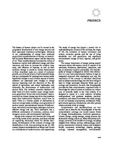
One of the main challenges to any methodology dealing with system design, in the steady state, is the complexity of the design space. The design space of an energy system may be described in a simplified way by three-dimensional coordinates as shown in Figure 1.1. For a given objective function (efficiency, cost, emissions, s a f e t y , . . , or combinations), an optimal design has both an optimal structure (devices and their connectivity) and an optimal design point (a decision vector of thermodynamic variables and devices' design and manufacture variables). Because structural changes are evolutional and design point changes are multi-dimensional, the topology of the design space is indeed complex and not homogeneous. With co-generating systems of
Min. Cost Min. Fuel Min. Maintenance Max. Safety Max. Reliability Max. Flexibility
CRITERION ~
. . . . . . . . . . . . . . . . . . . . . . . . . . .
. . . . . . . . . . . . . . . . . . . . . . . . . . .
or Combinations
II Changes involve discontinuities that Improved are associated Design Point with changes in configuration, connectivity, materials, types of devices, layouts,.... ~
Feasible Design Point
Changes involve a large number of variables that appear as dependent, independent, equalities, inequalities .................. They may represent efficiencies, flow rates, heat rates, fluid properties, dimensions, cost indices................
PARAMETRIC CHANGES ...
..........I .........-" ]
...
............. 9 ..............
MATHEMATICAL CONTINUOUS
STRUCTURAL/ CHANGES EVOLUTIONAL INNOVATIONAL Figure 1.1 The complexity of the design space for time-independent production systems.
Introduction
3
more than one product, the product ratio's dependence is an added complexity influencing structural changes. For systems meeting variable demand profiles, the timedependent production complicates matters further by adding the time dimension to the design space. Means of enhancing the search in both directions of design point and structural changes are needed with the understanding that there is no unique optimal solution. Usually there is no single significantly superior solution and more than one solution may share the same objective by narrow differences. The search is, therefore, a search for an optimum solution rather than the optimum. Moreover, there is no optimization method yet that guarantees global optimum for a multi-variable problem. All recent energy analysis methodologies are outcomes of the challenge to handle such a complex space and the challenge is continuing. 1.3
The Level of Details of a System Description
The level of details of a system description depends on the purpose of analysis. The describing element that receives inputs leading to outputs ranges from a nano-element to one large black box. When seeking higher efficiency and lower cost, two levels of details are usually needed. In the synthesis of the system, the adequate element is a black box representing an elementary energy conversion process. Heat exchange, expansion and compression and combining two streams, or separating a stream into two with or without change in composition, are examples of elementary processes. Grouping elementary processes that do not occur simultaneously into a larger black box reduces the chance of improving efficiency. In designing a device that performs an elementary process, a higher level of details is needed by splitting the elementary process into smaller or even differential elements. Zooming on differential elements may be needed, e.g. to assure a stress limit is not exceeded. System description involves both continuous and discrete variables. Most of the variables participating in the modeling of properties, processes and geometry can be treated as continuous. Most of the variables participating in describing the structure of the system, such as process connectivity and type and device materials, are discontinuous. However, a few continuous variables may force connectivity changes such as gas turbine firing temperature, or force different material such as prime steam condition. Also, a few discrete variables may be treated as continuous such as the number of repeatable pattern of stages. 1.4
The Interaction of Energy and Materials Requirements
The requirement of the materials processed and shaped as an energy conversion device and the requirement of the driving energy of the device to perform its task in any particular situation are both expenses often in strong conflict. The first may be quantified by a design characterizing dimension of the device, usually a surface area, and the second by a fuel resource consumption (exergy destruction or entropy creation as will be explained in Chapter 2). In monetary units, the first manifests itself as a
4
The Thermoeconomics of Energy Conversions
capital cost and the second as a fuel resource cost. The cost of a device is the sum of both costs rated per unit time. The minimization of the cost of each device in a system often goes hand in hand with minimization of the cost of the overall system. This will turn out to be a useful principle.
1.5
The History of Thermoeconomics Development
The interaction between cost and efficiency has always been recognized qualitatively. However, the interest in formulating the interaction was first highlighted in connection with seawater distillation in the 1960s to gain insight in the interaction between the surface of separation requirement and energy requirement. The first landmark of the work on thermoeconomics was by Tribus and Evans [1] in 1962 and dealt with seawater desalination processes. The development by E1-Sayed and Evans [2,3] followed in 1970. Professor Tribus coined the word "thermoeconomics". In 1985, Professor Gaggioli initiated the interest in extending the development to all kinds of energy-intensive systems [4,5]. Since then the interest has spread nationally and internationally by a large number of investigators and the development is still continuing. References [6-10] may be a fair representation of the main schools of thought that evolved in the last thirty years in optimal system design. Most investigators have been pursuing the following targets: 9 Capabilities to pinpoint and quantify energy inefficiencies. 9 Provision of insight to improvement. 9 Automation of certain aspects of the search for improvement. Investigators may have differed in the techniques of managing system complexity. Four techniques may be identified. They are all system-structure oriented in contrast to the purely mathematical equation-solution oriented of conventional optimization: 1.
2.
3.
4.
Use a system decomposition strategy consistent with the mathematics of optimization whereby internal prices are computed not assumed. Most of work by this technique comes under "thermoeconomics". Assume fair internal pricing techniques for system decomposition. Most of the work done by this technique comes under "exergoeconomics" and sometimes under "thermoeconomics". Consider a composite heat exchange profile of all heat exchange processes to identify where to add heat, to reject heat, to produce work or/and to supply work appropriately. All the work done by this technique comes under "pinch technology". Let the computer automate the analysis by supplying it with a large database of devices and their characteristics. All the work done by this technique comes under "expert systems" or "artificial intelligence"
The first two techniques treat a problem as a heat-power network starting with fuel input(s) and ending with specified product(s). The third treats a problem as a heat
Introduction
5
recovery problem by a heat exchanger network. The fourth treats a problem as a selection from a large reservoir of solutions by an artificial intelligence code. All the four techniques are applicable to any energy system. Although the selection approach is a fast pragmatic approach, it has less impact on innovative energy conversion devices. This book belongs to the first technique. Intensive analysis is central and innovation is targeted. General references of interest to energy analysis and its further development are listed at the end of this chapter.
1.6
The Question Posed for Thermoeconomic Analysis
Models and computations in thermoeconomic analysis are formulated simply to answer the following question: "Is there a system concept that can have higher energy efficiency and lower unit production cost than an existing one under the same boundary conditions?"
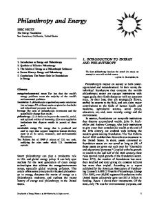
A cost/efficiency plane as shown in Figure 1.2 summarizes the results of the investigated systems and helps to find an answer. A higher-efficiency lower-cost system is accepted. A higher-cost lower-efficiency system is rejected. A higher-cost higherefficiency system requires further research and development. A lower-cost lowerefficiency system requires the consideration of fuel scarcity and environmental concerns beside cost and efficiency. A positive answer often exists or will exist. The answer may be a new concept readily available for immediate application. The answer may require a short-term R&D or may require a long-term R&D. A negative answer is rather unlikely. The answer also implies that the analysis is always relative to a current situation of defined physical and economic boundary conditions and not in an absolute sense. A life-cycle analysis is in the background and is not of primary concern.
A measure of cost
Reject
Continue R&D ...................
......................
Alternative design
............i~xisting"case......~Accept
"~" Existing plant
Consider depletion and environment
I~ A measure of efficiency
Figure 1.2 Cost/efficiency diagram.
1.7
The Importance of an Integrated Database
Computer-aided analysis requires communication with specially designed database for the most frequent information called for. The frequently needed information for
The Thermoeconomics of Energy Conversions
6
thermoeconomic analysis is made up mainly of three sets: 1. 2. 3.
Thermodynamic and transport properties of working fluids. Models of the elementary processes that constitute the building blocks of a system. Cost models for those devices performing the system's processes.
The extent of the database depends on the family of systems of interest.
The Main Pillars of Thermoeconomic Analysis
1.8
Thermoeconomics, as presented here, rises on three main pillars: 1. 2. 3.
Improved thermodynamic analysis. Improved costing analysis. Enhanced optimization.
The pillars are explained in detail in the following four chapters, 2 to 5, assuming the steady state. Extension to time-dependent systems is considered in Chapter 6. Simplified tutorial problems and examples of their solution are included in these six chapters to help grasp the basic tools of modeling, computation and optimization. Application to actual problems is considered in Chapter 7. Base-load and variable-load energy systems are considered. Base-load systems include examples of emerging technologies. Accompanying computer programs demonstrate the application details. The computer programs are listed and briefly described in Chapter 8. Several supporting and refreshing appendices are presented at the end of the book.
1.9
General References
1.9.1
Methodology developments
1. Tribus, M. and Evans, R. (1962). The Thermoeconomics of Sea Water Conversion, UCLA Report No. 62-63, August. 2. E1-Sayed,Y. and Evans, R. (1970). Thermoeconomics and the design of heat systems, Journal of Engineering for Power, January, 27-35. 3. E1-Sayed, Y. and Aplenc, A. (1970). Application of the thermoeconomic approach to the analysis and optimization of a vapor-compression desalting system, Journal of Engineering for Power, January, 17-26. 4. Gaggioli, R., Ed. (1980). Thermodynamics." Second Law Analysis, ACS Symposium Series 122. 5. Gaggioli, R., Ed. (1983). Efficiency and Costing, ACS Symposium Series 235. 6. E1-Sayed,Y. (1996). A second-law-based optimization, parts 1 and 2, Journal of Engineering for Gas Turbine and Power, 118(October), 693-703. 7. Torres, C., Serra, L., Valero, A. and Lozano, M. (1996). The productive structure and thermoeconomic theories of system optimization, Proceedings of ASME Advanced Energy Systems Division, AES Vol. 36, Nov, pp. 429-436.
Introduction
7
8.
Lazaretto, A. and Tsatsaronis, G. (1997). On the quest for objective equations in exergy costing, Proceedings of ASME, AES Vol. 37, pp. 197-210. 9. Linhoff, B. (1994). The use of pinch analysis to knock down capital costs and emissions, Chemical Engineering Progress, August, 32-57. 10. Sciubba, E. and Melli, R. (1998). Artificial Intelligence in Thermal Systems Design, Nova Scientific Publishers, 201 pages.
1.9.2
International symposia on energy analysis
(1987). Fourth International Symposium on Second Law Analysis of Thermal Systems, (ed. M. Moran and E. Sciubba), Rome, Italy, May 25-29. (1989). International Symposium on Thermodynamic Analysis and Improvement of Energy Systems, TALES '89, (ed. C. Ruixian and M. Moran), Beijing, China, June 5-8. (1990). Florence Worm Energy Research Symposium, (FLOWERS'90), (ed. S. Stecco and M. Moran), Florence, Italy, May 28-June 1. (1991). International Conference on the Analysis of Thermal and Energy Systems, (Athens'91), Athens, Greece. (1992). International Symposium on Efficiency, Costs, Optimization, and Simulation of Energy Systems (ECOS'92), (ed. A. Valero and G. Tsatsaronis), Zaragoza, Spain, June 15-18. (1995). International Symposium on Efficiency, Costs, Optimization, and Simulation of Energy Systems (ECOS'95), Istanbul, Turkey, July 9-14. (1995). IDA Worm Congress on Desalination and Water Sciences, Abu Dhabi, UAE, November 18-24. (1997). IDA Worm Congress on Desalination and Water Reuse, Madrid, Spain, October 6-9. (1998). International Symposium on Efficiency, Costs, Optimization, and Simulation of Energy Systems (ECOS'98), held in Nancy, France, July 8-10. (1999). International Symposium on Efficiency, Costs, Optimization, and Simulation of Energy Systems (ECOS'99), held in Tokyo, Japan, June 8-10. (1999). International Symposium on Thermodynamic Analysis and Improvement of Energy Systems, TAIES'99, Beijing, China, June 10-13. (1999). European Conference on Desalination and the Environment, Las Palmas, Gran Canaria, November 9-12. (2000). International Symposium on Efficiency, Costs, Optimization, and Simulation of Energy Systems (ECOS'O0), held in University of Twente, The Netherland, July 5-7. (2000). The International Conference on Seawater Desalination Technologies on the Threshold of the New Millennium, State of Kuwait, November 4-7. (2002). International Symposium on Efficiency, Costs, Optimization, and Simulation of Energy Systems (ECOS'02), held in Berlin, Germany, July 3-5. (2003). International Symposium on Efficiency, Costs, Optimization, and Simulation of Energy Systems (ECOS'03), held in Denmark, June 30-July 2.
1.9.3
Books on thermodynamics
Gaggioli, R.A., Ed. (1980). Thermodynamics." Second Law Analysis, ACS Symposium Series 122. Moran, M.J. (1982). Availability Analysis, A Guide to Efficient Energy Use, Prentice Hall. Kotas, T.J. (1984). The Exergy Method of Thermal Plant Analysis, Butterworth. Szargut, J., Morris, D. and Steward, F. (1985). Exergy Analysis of Thermal, Chemical and Metallurgical Processes, Hemisphere Publishing Corporation.
8
The Thermoeconomics of Energy Conversions
Reid, R., Pruasnitz, J. and Poling, B. (1989). The Properties of Gases and Liquids, 4th Edition, McGraw-Hill. Van Wylen and Sonntag (1996). Fundamentals of Classical Thermodynamics, John Wiley.
1.9.4
Books on optimization and equations' solvers
Wilde, D.J. and Beightler, C.S. (1967). Foundations of Optimization, Prentice-Hall Inc. Intriligator, M. (1971). Mathematical Optimization and Economic Theory, Prentice-Hall Inc. Wismer, D. and Chattergy, R. (1978). Introduction to Nonlinear Optimization, A Problem Solving Approach, North-Holland Series in System Science and Engineering. Chepra, S. and Canale, R. (1988). Numerical Methods for Engineers, 2nd Edition, McGraw-Hill Publishing Company.
1.9.5
Books on the design of energy conversion devices
Hoyt, H. and Sarofim, A.A. (1967). Radiative Transfer, McGraw-Hill. Siegel, R. and Howell, J. (1981). Thermal Radiation Heat Transfer, 2nd Edition, Hemisphere Publishing Corporation. Rohsenow, W., Hartnett, J. and Ganic, E. (1985). Handbook of Heat Transfer Applications, 2nd Edition, McGraw-Hill Book Company. Cohen, H., Rogers, G. and Saravenamuttoo, H. (1987). Gas Turbine Theory, 3rd Edition, John Wiley. Sabersky, R., Acosta, A. and Hauptmann, E. (1989). Fluid Flow, A First Course in Fluid Mechanics, 3rd Edition, Macmillan Publishing Co.
1.9.6
Books on optimal design
Robert Edgerton (1982). Available Energy and Environmental Economics, Lexington Books. Richard Gaggioli, Ed. (1983). Efficiency and Costing, American Chemical Society ACS, Symposium Series 235. Edger, T.F. and Himmelblau, D.M. (1988). Optimization of Chemical Processes, McGraw-Hill Company. Papalambros, P.Y. and Wilde, D.J. (1988). Principles of Optimal Design, Modeling and Computation, Cambridge University Press. Bejan, A., Tsatsaronis, G. and Moran, M. (1996). Thermal Design and Optimization, John Wiley and Sons Inc.
1.9.7
Books on emerging technologies (fuel cells and solar cells)
Appleby, A.J., Ed. (1987). Fuel Cells: Trends & Research and Applications, Hemisphere Publishing Corporation, Washington, New York, London, 295 pages, 23 articles, ISBN 3-540-17631-4. Yuri V. Pleskov (1990). Solar Energy Conversion." A Photoelectrochemical Approach, Springer-Verlag, 163 pages, ISBN 3-540-51474-0. Minh, N.Q. and Takahashi, T. (1995). Science and Technology of Ceramic Fuel Cells, Elsevier, Amsterdam, Lausanne, New York, Oxford, Shanon, Tokyo, 366 pages, ISBN 0-444-89568-X.
Introduction
9
Karl Kordesch and Gunter Simader (1996). Fuel Cells and Their Applications, VCH, Weinheim, New York, Basel, Cambridge, Tokyo, 375 pages. Jeffrey A. Mazer (1997). Solar Cells: An Introduction to Crystalline Photovoltaic Technology, Kluwer Academic Publishers, Boston, Dordrecht, London, 101 Philip Drive, Assinippi Park, Norwell, Massachusetts 02061.
This Page Intentionally Left Blank
2 Improved Thermodynamic Analysis Improved thermodynamic analysis extends the conventional thermodynamic computations to include the second law of thermodynamics quantitatively rather than qualitatively. The extended computations permit assigning fuel consumption to each process in a system. Fuel here means the input energy resource(s) often applied at one or two locations in the system boundaries. The energy resource may be fossil fuel, power, heat or any other driving resource. Thus, the way a fuel is utilized throughout a system is revealed. Processes of high fuel consumption are identified. Means of fuel saving are inspired by a structural change of the system or/and by a change in design point. New avenues of research and development are uncovered. The extended computations may be easily understood from the well-known definition of the adiabatic efficiency of a turbine or a compressor. Ideal adiabatic work (isentropic) is obtained when the entropy remains constant. Actual adiabatic work is associated with entropy creation. The efficiency relates the actual work to the ideal. The extended computations are simply entropy balance computations beside the conventional mass, energy and momentum balances. Entropy is conserved in an ideal process and is created in any real process. Efficiency-related variables of a process such as pressure losses, adiabatic efficiencies, heat-exchange effectiveness permit the computation of the amount of entropy creation S C. The created entropy is the difference between the actual process change of entropy and that of its corresponding ideal process. The process inefficiency (irreversibility) is measured as a lost work potential = To, Sc, where To is an ultimate sink temperature. Ideal processes do not create entropy. They measure 100% on the efficiency scale. It is important to note that since property relations and conventional balance equations along with efficiency variables can solve an energy system problem, engineers never bothered in the past to perform entropy balances. A more complete picture of efficiencies and inefficiencies is obtained by using a general work potential function known as exergy. For simple chemical systems it represents the maximum useful work relative to a dead state environment defined by pressure Po, temperature To, and composition {)(co}.
12
2.1
The Thermoeconomics of Energy Conversions
The Exergy Function
The exergy function is a general work potential function for simple chemical systems. The function evolved from the work of Carnot and Clausius, and is due to Gibbs (1978). The function is:
Es-
U+Po,V-To,S-~lZco,Nc
(2.1)
Es is the maximum work that could be obtained from a sample of matter of energy U, volume V, number of moles (or mass) of each matter species Nc when the sample of matter is allowed to come to equilibrium with an environment of pressure Po, temperature To, chemical potential #co for each species Nc. The same expression measures the least work required to create such a sample of matter out of the same environment. Various special forms of potential work have been defined to meet specific needs such as Helmholz and Gibbs free energies. A form useful to second law computations for systems in the steady state is:
Ef-
H-
To, S-
~_~#co, Ni
(2.2)
Equation 2.2 is a flow exergy. For convenience, it is often expressed as the sum of two changes: (1) A change under constant composition {Are} from the state at P and T to a state at a reference Po and To. (2) A change under constant Po and To from composition {X~} to a state at reference {)(co}. The state at Po, To and {Xco} defines the reference dead state environment for computing exergy, i.e:
Efwhere (H ~ - To 9 S~
2.1.1
(H - H ~ - To 9 (S - S ~ + ~--~(#c - #co) * Nc
(2.2a)
Vo,Xc = ( ~ lzc * Nc)t,o, Vo is used.
A derivation of the forms of exergy
A derivation of Equations 2.1 and 2.2 may be obtained with reference to Figure 2.1 by considering mass, energy and entropy balance equations for a simple chemical system. Figure 2.1 shows a system of mass M at pressure P, temperature T and of composition {X~} interacting with a large reference environment at pressure Po, temperature To, and composition {)(co} where {co} are the system species at the composition of the reference environment {)(co}. The state of the environment is a dead state where no changes happen. Also the system has matter and heat interactions by other systems represented by dmi and dQ. Matter dmi is at T;, P / a n d X~/. Heat dQ is at Tq. A set of ideal devices, in an abstract sense, is assumed to include expanders, compressors, pumps, selective membranes, chemical reaction cells and heat exchangers. Each device extract the maximum work or asks for the minimum work while exchanging heat dQo at To with the dead state environment. Figure 2.1 assumes work extraction. In a time period dt, dmi and d M acquire the pressure, the temperature and the composition of the environment, respectively. The question is how much work can be tapped in the period dt ?
Improved Thermodynamic Analysis
13
p ther Systems I ~lmi at Pi, Ti, {Xci}
~lWu [~
inH
I
]
OQ atTq I
l
l
~. [dQoat To [
IAbstract Ideal Set of Devices I [dmi, dM at
Vo,To,{Xco I
A System at T, P, {Xc} ead State Large Environment
~t
iston I
Figure 2.1
Po, To {Xco}
An illustration of exergy derivation.
In a time period dt, mass balance, energy balance and entropy balance are: Mass Balance (species and bulk): Stored = I n - Out dMc = Xr
(2.3)
9 dmi - Xce * dme
(2.3a)
d M = dm i - dm e
Energy Balance: Stored = In - Out d U - d Q - dQo - dWu - Po * d V + Hi * dmi - Z
g c e * yce * d m e
(2.4)
d V is a volume difference of mass d M at P , T , { X c } and the same mass at To, Po, {Xeo}
Entropy Balance: Stored - In - Out + Created d S - dQ
Tq
dQo Jr- (~S cr -Jr-Si * dmi - Z
To
See * Xce * dme
(2.5)
Hce, Sce are partial values of exiting species to environment. Multiply Equation 2.5 by To and subtract from Equation 2.4 dQ 9 (1
-
-- Z ( g c e
To~ T ) - d W u -
To * ~ S Cr + ( H i -
To * Si) * dmi
- To * Sce) */~fce * dme -- d U + Po * d V - To * d S
(2.6)
Let the chemical potential per unit mass be/z. In the t e r m 2 ( g c e - T o * S c e ) * Xce * d m e of Equation 2.6, (Hce - To * Sce) is a chemical potential lZco in equilibrium with ambient
14
The Thermoeconomics of Energy Conversions
and X~e 9
=
Z(ge
Xci , dmi - dMc (by Equation 2.3), then - To * Se) * ~ce * dme -- ~_~ #co * Xci * dmi - ~_, ,co * dMc
(2.7)
Substituting Equation 2.7 in Equation 2.6 then dQ 9 (1 - T o / T ) + (Hi - To * Si - Z = d U + Po * d V -
To * d S - Z
UcoX~i) * dmi - dWu - To * 8S ~r
(2.8)
ucodMc
For an ideal set of devices, T o , 8S er= 0 and d W u is expressed by the remaining three terms of Equation 2.8 which have to be potentials for work or in other words exergies. Let E represents an exergy identified by a superscript, then Equation 2.8 becomes: dE q + dEf-
d E w - 8D - d E s
(2.9)
where (2.9a)
d E q = dQ 9 (1 - To~ T) dE[-
(Hi-
To* Si-
~ _ , U c o X c i ) * dmi
(2.9c)
d E w = dWu d E S - d U + Po * d V - To 9 d S - ~ 6D = To 9 6S e"
(2.9b)
ucodMe
(2.9d) (2.9e)
Equation 2.9 is an exergy balance equation. In ideal conversions, exergy destruction 8 D - 0. Each of dE q, dEfi, and d E s represents d E w as a work potential in the absence of the other two: d E q is due to Carnot and represents the maximum work for a closed system ( d E [ - O) in the steady state ( d E S = 0). d E [ represents the maximum work if a flowing stream interacts directly with the reference environment and comes in complete equilibrium with it. 9 If the stream does not exchange species with the reference environment then dmi = dine = dm all of the same composition and the change from "in" to "out" is d E f = ( d H - To * dS) 9 dE s as a decrease represents the maximum work obtainable from a system of mass M as d M comes to complete equilibrium with the reference environment. 9 If species are not exchanged then d E S = d U + Po* d V - T o , d S (Keenan Availability). 9 If the volume remains constant as well then d E s = d U - To 9 d S (Helmholz Free Energy). 9 If instead the pressure of the system is same Po then d E = ( d H - T , dS)ro, Po (Gibbs Free Energy).
Improved Thermodynamic Analysis
15
In the presence of exergy destruction 6D = T o , S cr, Equation 2.9 becomes: d E q + d E f - ( d E w + 6D) -- d E ~
(2.10)
The actual work is reduced from the maximum by the exergy destruction. Integrating Equation 2.9d under the constant environment properties Po, To, {#co}, noting that end state is the environment at zero exergy, Equation 2.1 is obtained. For a constant flow per unit time M - d m i / d t , Equation 2.9b reduces to Equation 2.2 for the flow exergy. Some useful forms of the flow exergy, Equation 2.2 are listed in Appendix 9.1. The superscript f is dropped, i.e. E-- E f 2.1.2
Exergy balance and entropy balance
A systematic way to reach exergy balance from entropy balance is to multiply the entropy balance equation by sink temperature To and subtract from the energy balance equation as done with Equation 2.6. Exergy balance is used when interest is in both exergy and exergy destructions. Entropy balance is used when interest is limited to exergy destructions. Both balances can be performed around a system, subsystem, compound process or elementary process. In the steady state, exergy balance per unit time or per unit reference matter takes the form of the following equation: Z I N Eb -- Z O U T Eb @ D
(2.11)
{Eb} are exergies entering and leaving at the boundaries of the entity. D is the exergy destruction within the entity (by heat, shaft work, and flowing matter)
Eb = E q -+- E w + E f E q = Q 9 (1
- (To/Ta))
(2.1 lb) (2.11c)
E w = W, Ef = M
(2.1 l a)
9e
(e
per unit matter)
(2.11 d)
The following equation is for entropy balance in the steady state: Z O U T Sb -- ~-~IN Sb -- Scr
(2.12)
{Sb} are entropies entering and leaving at the boundaries of the entity. S Cris the created entropy Sb -- S m nt- S q
(by flowing matter and heat)
(2.12b)
S q = Q/Tb Sm = M * s D = To 9 S Cr
(2.12a)
per unit matter)
(2.12c)
(see Equation 2.9e)
(2.12d)
(s
16 2.1.3
The Thermoeconomics of Energy Conversions The dead state environment
A real dead state environment does not exit but may be idealized as a gas, a liquid or a solid. Atmospheric air, pure water, seawater and abundant minerals at ambient pressure and temperature may serve as natural dead state environments. When a natural environment is selected (e.g. atmospheric air) and the composition of a particular species (e.g. fossil fuel) cannot be set accurately in the environment, an equilibrium chemical reaction is introduced as an intermediate process in which the products of the reaction have their equivalent in the environment. This can also be used to establish an equivalent equilibrium composition of the missing species in the environment. A working fluid operating in closed circuit such as a refrigerant may have the dead state environment with the working fluid itself being at ambient temperature and suitable pressure, because in this case there is no interest in an interaction with an environment of different composition. The choice of a dead state environment is tied to the interest in the interaction with it. For examPle a mineral resource may serve as a dead state environment to reveal the minimum work in extracting desired species from the resource.
2.1.4
Fuel resource allocation to processes in a system
All energy conversion systems are driven by one or more energy driving resources. The utilization of the driving resources throughout a system gives a transparent picture of how the system processes share the driving resources. In an ideal system the exergy of a driving resource is converted completely to the exergy of the product(s). All processes are exergy transmitters. In real systems all processes destruct exergy beside transmission. All processes induce resource penalties due to their inefficiencies. Figure 2.2 displays the exergy destructions throughout the steady state processes of a simple combined cycle as well as the leaving exergy losses for an assumed design point listed in left column. Exergy destructions and leaving exergy losses are all fuel penalties. The figure shows how much of 195 M W input exergy became exergy destructions throughout the system before the net power 88.6 M W is tapped. An ideal system would require only 88.6 MW driving exergy. Different efficiencies of devices, different operating levels of pressures and temperatures and different system configurations give different distributions of system exergy destruction. They also give different distributions of the capital cost of the system. The computations include the flow exergy at each of the 17 interconnecting stations as well as powers, rate of heat exchanges and mass rates. For clarity these numbers are not included in the figure. For example, the flow exergy at location 3 is 211.9 MW; at location 4 is 50.07 MW; and at location 6 is 32.3 MW. The compressor power is 91.18 MW; the gas turbine power is 154.55 MW and steam turbine power is 25.41 MW. The difference in the chemical exergy of entering air and leaving exhaust gases is only 2.17 M W while the difference in the thermal mechanical exergy is 10.6 MW.
Improved Thermodynamic Analysis
17
Design Point P2 = 132 psia T3 = 1600 F P6 = 600 psia T8 = 100 F Pinch= 20 F Condnsr ATt = 10 F Suprhtr ATh = 50 F dp/P loss = 0.01, (9) Ad iabatic Efficiencies comp =0.85 GT =0.9 Stn T =0.9 pmps =0.8, (2) Boundary conditions Fuel:natural gas 8.8 lb/s P1 = 14.7 psia T1 = 8 0 F P15 =15 psia T15 =70 F P17 = 15 psia Dry8=satl Dryl0=satl Dry 11=satv
fuel species, 0 each at Po,To
Fuel
"l D=6.75 MW
ombustor
68 0MW
D=7.26 MW
Compressor
~-each at Po,To
= (AGR)Po,To
D=2.60 MW
Turbine
Steam Turbine
~?ower=88.6 1
4
~
=0.136 MW c =-12.95 MW
I 12
i7
6 Superheater]
.'ondenseJ
D= 0.98 MW
D=1.781~
11
MW I
~j=3.0 MW [
L6 D=.0001 MW
i
~ErM=m*[(h-ho)-To*(S-So)] xi c =m*[R*To* ~xi Log Xi]Po,To ~9 = To* S cr
~
J3 8 Boiler D3.17= MW 10
i
Decisions=3NL-2NP =51 - 20 =31 MW I jjc=_15.12MW ~~J~=1~
Zero exergy reference Po =14.69 psia To = 5 5 F {Xio}= as exist* * Note: For {Xio} to be the pure species, add the chemical exergy change from current composition to separated species. For air add (-19) Btu/lb. For combustion gases add
product species
--1 Fuel 195 MW []Chemical Exergy
2
Overall Eft = 0.4176
I
= 0.4860
9
Economizer
l
D-3.14 MW
14
9
1st law 2nd law
D=0.027 MW
(-21.89) Btu/lb. For H20
add nothing.
Figure 2.2 process.
Exergy destruction in a simple combined cycle: a method of allocating fuel to each
Figure 2.2, a result of second law analysis, gives a clear energy picture of a system. However, the cost picture of the system is, so far, absent.
2.2
T h e T h e r m o d y n a m i c A n a l y s i s o f a S y s t e m in the S t e a d y S t a t e
The computation of a design point of a system in the steady state, as shown in Figure 2.2, is a key procedure in the further analysis of a system of a given configuration. Enhanced analysis calls for fast computation of this key procedure. The procedure boils down to a number of equality constraining equations and a larger number of variables. The difference is a set of decision variables to be assigned with a purpose in mind such as a targeted level of a system's overall efficiency. The selection of these decision variables from all the participating variables has significant effect on the speed of computation. The selection that leads to sequential solution of the set of equations (as contrasted to simultaneous) gives the fastest computation. A sequential solution has
18
The Thermoeconomics of Energy Conversions
dependent variables within the diagonal of the matrix of the equations and the dependent variables. The decision variables given in the column of Figure 2.2 allows the sequential solution of the considered simple combined cycle. The following sections to the computational algorithm of a design point deal with the number of variables, constraints and decisions as well as with the approach to sequential equation solver.
2.2.1
Variables, constraints and decisions
A system defined via a flow diagram will have N~ states, Np processes, Nv variables and Nq equality constraints. The decision variables Na = Nv - Nq = (Nv - NK) -- (Nq - NK) where NK represents a subset of Nv and a subset of Nq of equal number. NK may be excluded from Nv and from Nq without affecting the number of decision variables. Thermodynamic and transport properties of the working fluids and their corresponding equations are examples of the subsets that can be excluded when deciding the number of decision variables. They may, however, appear in the matrix of the constraining equations and their dependent variables. In the absence of chemical separations or combinations, each state has a minimum number of variables per state to compute (e.g. P, T, {X~} and Mass, though P and T may be exchanged by two other properties such as P and H or T and S). The equal subsets take care of the desired property vector. Each process has one mass balance equation and one energy balance equation per process. Discounting property subsets of equal variables and their corresponding equations, the number of decision variables Nd becomes: (2.13)
Nd = 3 * N~ - 2 * Np
In the presence of chemical separation or/and combination, the variables are increased by the composition of the participating species {Xz} in the participating chemical processes and the equations are increased by the species mass balance equations. Thus: Nd -- 3 , N~ - 2 , Np --~-Z r ( N c ,
r -1)
, Ns, r - Z r N e q n ,
r
(2.14)
where r is the number of processes involving chemical change. Nc, r is the species of the stream of largest number of species. (Ne, r - 1 ) takes into consideration the total mass of the stream accounted for in the first term 3 , Ns. Ns, r is the number of states of each reaction r. Neqn,r is the number of mass balance equations in each reaction r. For a combustion process having N s = 3 and N e = 7 and Neqn=6, the decision variables increase by 12, which is the composition of air and fuel. The six mass balance equations determine the composition of the products of combustion.
2.2.2
The approach to sequential equation solver
It is often possible to find more than one sequential equation solver for a system configuration. When this is not possible, minimizing the number of dependent variables to be solved simultaneously is still desired for fast computation.
Improved Thermodynamic Analysis
19
A sequential equation solver is sought by following the variables of the system and not the sequence of the connectivity of its devices. A solution path is best visualized by mentally solving the system without computation whereby the decision variables and the sequence of computing the dependent variables are identified. Computation often starts with pressures, temperatures, compositions and masses related directly by plus or minus to the selected decisions. The computation of states of known pressure, temperature and composition follows. Mass and energy balance equations are applied to the processes having sufficient known states to determine more masses and states until all states are computed. A state is a vector of thermodynamic properties that should consist at least of pressure, temperature composition, specific volume, enthalpy, entropy, exergy and relative mass. The vector is useful to the consistency of the detailed analysis of the system. A computerized general sequential equation solver for any system configuration must have built-in guards against premature computations. The states and the processes of a system configuration go through repeated runs. In each run only mature computations are performed. The runs stops when all state vectors are computed, i.e. a system design point is obtained for further system analysis. An incidence matrix can express the flow diagram of a system. The columns represent the system streams and the rows represent the system processes. A cell (i,j) represents a streamj connected to process i. Input and output streams are differentiated by positive and negative signs. Pressure, temperature, composition and a mass relative to a reference mass are sufficient to indicate that the state of a cell is determined. A solution is reached when all states are known. The incidence matrix of Figure 2.2 is given in Figure 2.3. Processes of splitters and mergers of matter, heat or work may be excluded for simplicity since the quantities are related directly by plus or minus signs similar to the initial computations related to the decision variables. The incidence matrix may be expanded to identify a sequential computational algorithm free from system iterative loops for fast computation. For modular description of systems, this is analogous to diagonalizing the solution of a set of simultaneous equations. For a set of thermodynamic decision variables, sequential solution of mass and energy balance equations requires handling the models of the system processes in a particular order. Figure 2.4 shows an expanded incidence matrix that handles the process models in a sequence that is free from system iterative loops. The thermodynamic decisions considered are process efficiency parameters and essential stream parameters. The efficiency parameters are indicated in column 18. They are the adiabatic efficiencies of turbines and pumps {r/}, pressure loss ratios of the streams {dP/Pin} and the temperature differences that control the heat exchange processes (dTh7--T4-T6, dTc7--T13-T10, and dThlo= T7-T17). The essential stream parameters are indicated under the streams. They are boundary parameters and upper and lower values of pressures or temperatures. Target computations for each process model are indicated in column 19. A figure such as Figure 2.4 visualizes the mental solution of a system. If both the processes and the streams were numbered to follow the sequence of computation, the incidence matrix would appear diagonalized even though the matrix is not square. The stream sequence [1,2,5,3,4,6,10,13,8,9,7,15,16,17,11,12,14] diagonalizes
20
The Thermoeconomics of Energy Conversions
1. c o m p r e s s o r
1
2
+
-
2. g a s t u r b i n e
3
4
+
-
5
6
7
8
9
+
-
10
11
12
13
14
15
16
17
3. s t e a m t u r b i n e 4. f e e d p u m p 5. c o o l i n g p u m p 6. c o m b u s t o r
+
-
7. s u p e r - h e a t e r
+
_
-
+
+
15 P T
16
17 P
-
+
9. e c o n o m i z e r +
10. c o n d e n s e r
Figure 2.3
--{-
+
8. b o i l e r -
The incidence matrix of the flow diagram 2.2.
1
2
P P T {x } M=I
3
Streams and Stream Decisions 4 5 6 7 8 9 10 11 12 P P T {x }
T
T satl
satl
13
14 P
Efficiency Decisions
Target Computations
satv
Processes 1. 6. 2. 7. 4.
compressor + combustor gas turbine suprhtr/blr ## feed pump
+
+
+
-
+ +
3. s t e a m t u r b i n e 5. c o o l i n g p u m p 10. c o n d e n s e r 5. c o o l i n g p u m p 7. s u p e r h e a t e r 8. b o i l e r 9. e c o n o m i z e r
TI dp/p r~ {dp/p }, dTh7, dTc 7 1]
+
+
-
-
-
rl +
+
+
+
+
+ -
+ -
+
+
+ -
-
-
]] {dp/p }, dThlo
T2,Wl# P3, { x3 }, M3,M5 T4,W2 M6(steam) Ts,T9,W4 W3 T16,w5 Mlv(cooling)
rl ---
W5 Tl2 Check balance
--
Tl4
# W=M*w # # C o m b i n i n g the s u p e r h e a t e r a n d the b o i l e r m a i n t a i n s s e q u e n t i a l solution by a v o i d i n g tear. T h e e n e r g y b a l a n c e here d e t e r m i n e s m6 ( m a s s o f s t e a m relative to air)
Figure 2.4 Decisions and sequence of computation. the matrix. Transforming the flow diagram of a system and its decision variables to an expanded incidence matrix helps to identify the sought sequential solution.
2.3
Tutorial
The following solved examples and problems are meant to be exercises in second law analysis in the steady state. They use randomly both SI system of units and the British system of units. Refer to the useful forms of flow exergy of Appendix 9.1. Solved examples are followed by tutorial problems.
2.3.1
Solved examples
Example 1" Calculate the minimum work required at 1 atm and 25~ (or 75~ to separate 1 mol of air (0.79 N2 and 0.21 02 mol fractions) into nitrogen and oxygen in the steady state.
Improved Thermodynamic Analysis
21
.79N2, .2102 .-I Ideal Separator
79N2 at Po,To
"1
at Po,To
I
" .21 O2 at Po,To
I
1
Dropping the superscript f, consider 1 mol of air as an ideal gas flowing at E -- ( H - H ~ - To * ( S - S ~ --~-'~(#i2
#il) * N i
-
+ Z(~i-
#io) * Ni
-- R 9 To * (XN2 *
Po, To
(2.2a)
( 1 ) ( 1 ) LN XI,N2 +Xo2 , L N Xl,O2
( ( 1 ) ( 1 )) = 8.314 9 298 9 0.79 9 LN b ~ + .21 9 LN ~ - 1273.4kJ/kgmol
((')
OR-1.987,535,
0.79,LN
~
+.21,LN
(')) .-~
-546.6Btu/lbmol
Example 2: Steam at 2 MPa and 260~ (or 300 psia, 500~ expands in a steam turbine of adiabatic efficiency 0.8 to a pressure 0.035 MPa (or 5 psia). Calculate the flow exergy at the inlet and outlet of the turbine, maximum power, actual power, isentropic power and exergy destruction per kg of steam flowing (or per lb). Consider a reference environment of pure water at 1 atm and 25~ (or 14.7 psia and 75~ 1258.h ~..H.............................................. . .1...................................... . \
1:P=300 psia, T=400F
.
.
.
.
.
.
.
.
.
.
.
.
.
.
.
.
.
.
.
.
.
.
960.7 889.7 837.8
.
............................................2sl " ~26~ ~ 2s)o
,...........................Z
~cfis of~=O
.~l!.,
2" P=5 psia V
H~ 43.1 ; S~ .084
75F,.43 psia ~
y
S
1.571 1.666
Under no change of composition: E = (H-
H ~ - To 9 ( S - S o)
At inlet E1 = (1258.1 - 4 3 . 1 ) - 535 9(1.571 - . 0 8 4 ) - - 4 1 9 . 5 Btu/lb (H1 - Hl,o = 420.3) At exit E2 = (1020.1 - 4 3 . 1 ) - 5 3 5 , ( 1 . 6 6 6 - .084) = 130.6 Btu/lb ( H 2 - H2,o= 130.7) Maximum power = E1 - E2 = 419.5 - 130.6 = 288.9 Btu/lb Actual work W = H1 - H2 = 238 Btu/lb Adiabatic efficiency ~ = 0.8 = W / ( H 1 - H2~)
22
The Thermoeconomics of Energy Conversions
Notice the approximate locus of zero exergy. The approximation is because the actual reference is sub-cooled liquid at Po, To and the locus reference is saturated liquid at To. Example 3: A low cost refrigerated wind tunnel operates below atmospheric pressure by allowing atmospheric air to do expansion work. A compressor raises back the tunnel exit pressure to atmospheric pressure. The tunnel inlet-to-throat static pressure ratio is 1.2. Expansion in nozzle is isentropic. Overall tunnel outlet-to-inlet pressure ratio is 0.9 at negligible velocities. The turbine inlet pressure is 1 atm and 25~ (or 75~ and exit pressure is .8 atm with adiabatic efficiency is 0.88. The exit pressure of the compressor is 1 atm and its adiabatic efficiency is 0.8. Compute the flow exergy at each station and the exergy destructions in the three devices. Per 1 lb of air flowing as an ideal gas of constant specific heats under no composition changes: E = (H -
H ~ -
To(S -
S ~ = cp 9 (T -
- To 9 cp 9 L N ( T / T o )
To)
+ R 9 To 9 L N ( P / P o )
Let cp = 0.24 Btu/lbR k = cp/cv = 1.4 R = cp - cv =0.24
- 0.24/1.4 =0.0686 Btu/lbR a uatl a l
Tunnel 3:0.72atm
nozl
TF
106 at
]
5(1
2:0.8atm
........ u}4
4(
9
108.3
.72atm
...........................j i;i......
.67 m
. . . . . . . . . . . . . . . . . . . . . . .
75
46
........ .~......... ;t'"" i..........................................
42
ii
;!si
20 4 : 1 atm
.8 atm
;i
l:75F, latm S btu/lbR
Exergy, exergy destruction and work in Btu/lb are as follows: E1 = 0 E2-0.24, (46-75)-535,0.24,LN( +0.0686,535, LN(?)
46+460)53-
- - 8
E 3 - 0 . 2 4 , ( 4 6 - 7 5 ) - 5 3 5 " 0 " 2 4 " L N ( 4 6 + ~60)53-
\11
Improved Thermodynamic Analysis
23
E4 - 0.24 9 (108.3 - 75) - 535 9 0.24 9 L N \ +0.0686,535,
LN(~)
108.3 + 460) ~j~
-- 0.239
E5 -- 0.24 9 (20 - 75) - 535 9 0.24 9 L N ( 20 ~+ 460']j .§ 0.0686,535,
L N ( 07" )~-
- - 14
W o r k by turbine W t = 7 W o r k on compressor W c = 15 Net work input = 8 Exergy destruction in turbine = E1 - E2 - W t = 0 - ( - 8 ) - 7 = 1 Exergy destruction in compressor = E3 - E4 + Wc = - 1 1 . 8 6 - .239 + 15 = 2.9 Exergy destruction in tunnel = E2 - E3 = - 8 - ( - 1 1 . 8 6 ) = 3.86
Example 4: Methane is burned with 20% excess air. The mixture enters a c o m b u s t o r at 1 atm and 25~ (or 14.7 psia, 75~ The products leave at 1 atm and l l00~ (or 14.7 psia and 2000~ Calculate the flow exergy at inlet and exit and the exergy destruction by the combustor. Assume an ideal mixture and complete combustion with Inlet 1 Move states 1,2 through reversible paths to account for G,H,S changes as P,T and {Xi}change till the dead state is reached
Ideal ~j] separator
Reactants Po,Yo,{Xi,1 }
moles {Xi, 1} CH4=I 0.0803 02 =2.4 0.1928 N2 =9.03 0.7254 COa=.0035 0.0003 H20=.0142 0.0011
12.4477 moles reactant mixture at Po, To Inlet state 1:
f
i i
' i
I
Reversible cooling
"1
' 12.4477 moles products mixture at Po, T2 Po,T2, {Xi,2}
Products (mixture)
Products
:l
71 El
Po,To, {Xi,2}
(products) i
:i i
i1 1
I Ideal merger
"1
Moles i {Xi,2 } 02 =.4 0.0321 N2 =9.03 0.7254 CO2=1.0035 0.0806 H20=2.0142 0.1618 Po,To, {Xi,2}
Products (mixture)
{Xi,o} 02 =.4 0.2086 N2=9.03 0.7850 CO2=1.0035 0.0003 H20=2.0142 0.0060
~l Ideal El merger
['1 El I~l (AHR)Po,To (ASR)(AG..... R) ..... El "1
(reactants)
Exit2
Po,T2, {Xi2 }
Moles {Xi,2} 02 =.4 0.0321 N2 =9.03 0.7254 CO2=1.0035 0.0806 H20=2.0142 0.1618
Po,To,{Xi,1} ,Exit state 2:
] Combustor [
~ ~ 1 {,Xi,o} 02 =.4 13.2086 N2 =9.03 0.7850 CO2=1.0035 0.0003 H20=2.0142 0.0060
Po,To,{Xi,o} (dead state)
Po,To,{Xi,o} (dead state)
24
The Thermoeconomics of Energy Conversions
no dissociation. The dead state is defined by 1 atm, 25~ (or 75~ 20% relative humidity and dry gas mole fractions of N2, 02, CO2: 0.7898, 0.2099, 0.0003 respectively. Average constant pressure specific heats in the range of interest for N2, 02, CO2 and H 2 0 (g) are respectively 7, 8, 12.95, 10.225 Btu/lb mol R (29.3, 33.5, 54.2, 42.8 kJ/kg K). Is the process adiabatic? For (AGR)eo,ro, (AHR)po, ro and (ASR)eo, ro refer to Appendix 9.5. Per 1 mol of methane flowing, assuming ideal gas behavior of constant specific heats:
E -- (H - H ~ - To(S - S ~ + ~ ( # i = Z
Ni * cpi * (T - To) - To * Z
+ R 9 To * Z
#io) :r Ui Ni * cpi * L N ( T / T o ) + R 9 To * Z
Ni * LN(P/Po)
Ni * LN(Xi/Xi, o)
The third term drops out because P - P o
E-- ZNi*cpi*(T-
all the way
T o ) - To* ~ N i * c p i *
L N ( T / T o ) q - R * To* Z N i *
LN(Xi/Xi, o)
Consider inlet state." The equation can be applied to inlet state 1 where the third term (chemical exergy) is the only active term representing reactants but methane has no known composition in the selected dead state environment. Introduce an ideal reaction process for methane as an intermediate process. Create a path for the process to the dead state or use its equilibrium argument to establish the composition of methane in the dead state environment. The chemical term becomes (in-out)"
R 9 To * ~
UiR * LN(XiR/Xi, o)
= (AGR)t,o, ro + R 9 To * Z
Nit, * CN(1/Xi, o) + R 9 To * Z
NiR * CN(Xi, o/1)
The last two terms are correction terms to account for ideal merging and separating.
(aGR)po, ro = - the formation free energies of the reaction CH4 -k- 2 9 02 = CO2 + 2 9 H2Oliq = 394374co2 + 2 9 237178H20 -- (50751CH4 -+- 2 9 0O2) kJ/kg mol methane = 817979 kJ/kg mol methane = 351668 Btu/lb mol
R 9 To 9 E N i e
9 LN(1/Xi, o) - 11129 Btu/lb mol methane
R 9 T o , ~_~ NiR * LN(Xi, o/1) - 10342 Flow exergy at inlet - 351668 + 11129 - 10342 - 352455 Btu/lb mol methane = 819810 kJ/kg mol methane
Improved Thermodynamic Analysis
25
Alternatively the following argument may be used to establish the equilibrium composition of m e t h a n e in an environment of oxygen, nitrogen, carbon dioxide and water vapor of k n o w n dead state composition: 2
1
--(AGR)Po, To -- R 9 To * L N ( K ) - alco2 , aH20/(aCH 4 9 a~:) where a is the activity. That reduces to the mole fraction for an ideal gas mixture at Po. A l t h o u g h this gives a very low mole fraction XCH4, LN(XcH~) participating in exergy c o m p u t a t i o n is f i n i t e = - 3 4 6 . However one may expect less accurate values. Establishing an equilibrium value for methane in the dead state environment gives: Flow exergy at inlet = R , T o , ~ N i R * LN(XiR/Xi, o)= 364697 Btu/lb mol m e t h a n e
Consider exit state." E
Nip * cpi * (T - To) - To * Z
-k R * To * Z Z
Nip * cpi * L N ( T / T o )
Nip * LN(Xip/Xi, o)
Nip * cpi - No2 * cp02 At- NN2 * CPN2 Av NCO2 * r
Af_NH20* CpH20
= 0.4 9 8 + 9.03 9 7 + 1 9 12.95 + 2 9 10.25 -- 99.86
Z
Nip * LN(Xip/Xi, o) - No2 * LN(XiP, 02/Xio, Oz)-+- NN2 * LN(XiP, N2/Xio, N2) + Nco2
*
LN(Xip, Co2/Xio, C02) -k- NH2o
*
LN(XiP, H20/Xio, H20)
= - 0 . 7 4 9 - 0.713 + 5.613 + 6.636 -- 10.787 E at exit - 99.86(2460 - 535) - 99.86 9 535 9 LN(2460/535) + 1.987 9 535 9 10.787 = 192230.5 - 81508 + 11467 = 122189.6 B t u / l b m o l methane Exergy destruction in c o m b u s t o r -
3 5 2 4 5 5 - 122189.6
= 230265.4 Btu/lbmole m e t h a n e
(AHR)Po, To = - t h e formation enthalpy of the reaction C H 4 + 2
9
O2--CO2-k-2
*
HzOliq
= 393522co2 + 2 9 2858381-12o - (74873cH4 + 2 9 0o2) k J / k g mol m e t h a n e = 890325 k J / k g mol methane = 382771 Btu/lb mol Heat delivered a n d / o r leaked during combustion process
Q - (AHR)Po, To -- ~
Nip * cpi * (T - To)
-- 382771 - 192230.5 -- 190540.4 Btu/lb mol m e t h a n e
Example 5: Ocean thermal energy conversion (OTEC) uses naturally occurring temperature differences between surface and ocean b o t t o m temperatures to produce power. In a particular location the bottom, the surface and the air temperatures are 4~ 25~ and 30~ Select a suitable dead state temperature. Relative to the selected dead state temperature, derive expression for the hot and cold streams of water m~ and mh as function of their mass ratio. W h a t is the mass ratio m~/mh that would produce m a x i m u m
26
The Thermoeconomics of Energy Conversions
work and what is the final temperature reached in this case? Assume constant specific heats. Ignore pressure losses, salt content differences and specific heat differences E - ( H - H ~ - To(S - S ~ + E ( # i
- #io) * N i -- m 9 cp 9 ( T - To - To * L N ( T / T o ) )
The chemical potential term and the pressure term are dropped. M a x i m u m power per unit of hot stream Wmax/mh = cp * (Th -- To - To * L N ( T / T o ) ) + m c / m h * cp 9 ( t o - ro - r o 9 L N ( r / r o ) )
Let To = constant (large environment) To = Tair = 30 nt- 273 = 303 K, To = Th = 25 + 273 = 298 K, To = Tc = 4 + 273 = 277 K,
Wmax/mh = 0.0417 + 1.837 * m o / m h Wmax/mh = 0.7766 * m o / m h Wmax/mh = 0.758
Let To = variable (hot and cold streams are the only participants and are finite, not large) M a x i m u m work occurs when no entropy is created: ASh + ,X& = 0 mh * cp 9 L N ( T h / T o ) + mo * cp 9 L N ( T ~ / T o ) = 0
mh 9 LN(Th) - m h 9 LN(To) + mc 9 LN(T~) - mc 9 LN(To) = 0 LN( T~ h) + LN( T m~) - LN( Tomh+mc) -- 0 L N ( T ~ h 9 T m~) = LN(Tomh+m~
T'; 'h , T T ~ T o - - T mm h(/h+mch)
TTh+ m~ * Tcmc/(mh+mc)
Example 6: A simple gas turbine cycle burning methane receives air at 14.7 psia and 85~ The compressor pressure ratio is 10 and its adiabatic efficiency is 0.82. The firing temperature is limited to 1600~ The pressure loss in the combustor is 0.01 the inlet air pressure to combustor. The turbine adiabatic efficiency is 0.88. Write a program of sequential equation solver to compute the system states expressed by temperature, pressure, enthalpy, and exergy. Express per lb of air flowing the exergy destructions in compressor, combustor and turbine. Use the following simplifying assumptions: Assume ideal gas behavior of constant specific heats: cpair =0.25 and Cpegas = 0.29 Btu/lb R Assume the exergy of fuel is Gibbs free energy at standard P and T (14.7 psia, 75~ Use the standard values for the zero exergy pressure and temperature. Ignore the thermal-mechanical exergy of fuel and the chemical exergy of inlet air and leaving exhaust gases. Equation 2.13 gives Na=3,Ns-2,Np=3,5-2,3=9
Improved Thermodynamic Analysis
27 5 fuel; . . . . . . . . . . . . . .
Let decisions be ml, P1, T1, P2, r3, P4, /]1, /]2, /]3Let P5 - P2 Decisions." m l - 1; P 1 - 14.7; T 1 - 80; P2-- 147; T 3 - 1600; P4-- 14.7 /71 - - 0 . 8 2 ;
112-- . 0 1 ;
/73 - - 0 . 8 8
Properties." Cv - - Cp - - R ; k -
t~
and
po
to
and
Po
Cp/Cv; kair -
1.4;
1.31
kgas --
for zero e n t h a l p y - 32~
and 14.7 psia
for zero e x e r g y - 75~ and 14.7 psia ~ Cp 9 L N ( T / T ~ - R 9 L N ( P / P ~
n--cp,(t-t S-
For air and gases = cp 9 ( t -
E TM -
H - Ho -
To 9 ( S - S o )
to) - To 9 cp 9 L N ( T / T o ) + R 9 To * L N ( P / P o )
From Example 4 for methane fuel: H c-
( A H R ) P o , To - -
EC-(AGR)eo,
ro -
382771/16 - 23923 Btu/lb 3 5 1 6 6 8 / 1 6 - 21979 Btu/lb
Essential system computation to obta& a solution." a~
qua io m2=ml
Hl =
Cpair* (tl -t ~
Dependent Variable m2 H1 T2s Wls Wl H2 T2 H3 m5 m3 m4 P3 T4s W3s W3 H4 T4 x ................ X ..........
Ta,s=T1, (pa/p0(kair-1)/kair ....~ ............ WI,s=ml*Cpair*(t2,s-tl)
Wl=Wl,s/~ 1
H2=H~ +W~/ml x t2=t~ H3 = %gas*(t3-t~ ms=m2* (H3-H2)/(HC-H2) x m3 =ms* +m2 x
X
5"............
X
X ............
x
~....... X
/
~"........ X ".-.......
X
X X".............. X
m4 =m3
)~...........--...... X X ............ X '"-......
P3=P2*(1-112) T4,s=T3 * ( P 4 / P 3 ) (kgas'l)/kgas W3,s--m3* Cpgas* (t3-t4,s)
X
t4---t~
X X
X"............. X"..............
x
W 3 = W 3 , s * I]3
H4=H3 -W3/m3
Di~onal
x
x
x .............. x
~ ........ X "'~.......... -....
28
The Thermoeconomics of Energy Conversions
F u r t h e r c o m p u t a t i o n f o r analysis E1 = Cp 9 (tl - to) - To * Cp 9 L N ( T 1 / T o )
+ R 9 To * L N ( P 1 / P o ) ;
E2 = Cp 9 (t2 - to) - To * Cp 9 L N ( T 2 / T o )
+ R 9 To * L N ( P 2 / P o )
E3 = Cp 9 (t3 - to) - To * Cp 9 L N ( T 3 / T o )
+ R 9 To * L N ( P 3 / P o )
E4 = Cp * (t4 - to) - To * Cp 9 L N ( T 4 / T o )
+ R * To * L N ( P 4 / P o ) ;
mnet "- W 3 -
last term = 0
ml
Whet (ms * H C ) ' "
Eff l
last term = 0
Wnet
E f f 2 = (ms * EC) '
Eff l
system first law efficiency
E f f 2 - system second law efficiency dumping
gases leaving turbine E f f 2 = ( W n e t + m4 * E 4 ) / ( m 5 * EC);
D1 = W1 - ml 9 (E2 - El);
leaving gases are considered a product
D = Exergy destruction
D2 = m5 9 E c + m2 * E2 - m3 * E3
D3 = m3 * (E3 - E4) - I413
2.3.2
Tutorial problems
Problem 1: Calculate the m a x i m u m power in kW of merging 0.79 mol N2 per second at 3 atm and 25~ and 0.21 mol 02 per second at 2 atm and 25~ to obtain air at 1 atm and 25~ Problem 2: One mole of methane is burned with 25% excess air in steady state adiabatic process. The mixture enters a combustor at 1 atm and 25~ The products leave at 1 atm. Calculate the temperature of the products of combustion, the flow exergy at inlet and exit and the exergy destruction by the combustor. Assume an ideal mixture and complete combustion with no dissociation. The dead state is defined by 1 atm, 25~ 100% relative humidity and dry gas mole fractions of N2, 02, CO2: 0.7898, 0.2099, 0.0003 respectively. Constant pressure specific heats as function of temperature in Kelvin in the range of interest are: CpN2 - 39.060 - 512.79 9 ( T / 1 0 0 ) - 1 5 + 1 0 7 2 . 7 Cpo2 -
9 ( T / 1 0 0 ) - 2 - 8 2 0 . 4 0 9 (T/100) -3
37.432 + 0.020102 9 (T/100)15-178.57 9 (T/100)-15+236.88 9 (T/100) -2
CpCo2 -
- 3 . 7 3 5 7 + 30.529 9 ( T / 1 0 0 ) ~
9 (T/100) + 0.024198 9 (T/100) 2
CpI-I2Og -
143.05 - 183.54 9 (T/100)~
9(T/100)~
9 (T/100)
Problem 3: Write a program of sequential equation solver for the thermodynamic analysis of the simple gas turbine cycle of Example 6. Then investigate by tables and graphs the influence of firing temperature, compressor pressure ratio, turbine and
Improved Thermodynamic Analysis
29
compressor adiabatic efficiencies on overall first law and second law efficiencies using the same simplifying assumptions. Problem 4: Compute the exergy per 1 kg of a pure water stream at ! atm and 25~ relative to dead state of air of relative humidity 25% at same pressure and temperature. How much of this exergy is tapped by evaporative cooling? ( E = 190.8 kJ/kg, Twb = 13.3~ 0.12%).
2.4
References
Evans, R.B. (1969). A Proof that Essergy is the Only Consistent Measure of Potential Work, Ph.D. Thesis, Thayer School of Engineering, Dartmouth College, Hanover, NH. Gaggioli, R.A., Ed. (1980). Thermodynamics: Second Law Analysis, ACS Symposium Series 122. Gibbs, J.W. (1878). On the Equilibrium of Heterogeneous Substances, The Collected Works, Yale University Press, 1928, Vol. 1, pp. 77. Keenan, J.H. (1941). Thermodynamics, John Wiley. Kotas, T.J. (1984). The Exergy Method of Thermal Plant Analysis, Butterworth. Moran, M.J. (1982). Availability Analysis, A Guide to Efficient Energy Use, Prentice Hall. Rant, Z. (1956). Exergie, Ein Neues Wort ffir Technische Arbeitsfahigkeit, Forsch Ing-Wis, Vol. 22, No. 1. Reid, R., Pruasnitz, J. and Poling, B. (1989). The Properties of Gases and Liquids, 4th Edition, McGraw-Hill. Szargut, J., Morris, D. and Steward, F. (1985). Exergy Analysis of Thermal, Chemical and Metallurgical Processes, Hemisphere Publishing Corporation. Van Wylen, G.J. and Sonntag, R.E. (1996). Fundamentals of Classical Thermodynamics, John Wiley.
This Page Intentionally Left Blank
3 Improved Costing Analysis Optimality implies a search space and an objective function to maximize or to minimize. The design space of an energy system, setting aside time-dependent production, is a complex search space as illustrated by Figure 1.1. The search for an optimal design involves a search over alternative system configurations and for a given configuration over its alternative design points. The number of feasible design points is generated by the large number of decision variables that represent the degrees of design freedom of a given configuration. This number is large even when the objective function is a thermodynamic function such as efficiency or fuel consumption. When the objective function has other aspects beside efficiency such as cost, the decision variables become diverse and their number increases further. In engineering, the objective function is usually a multi-criteria function. Some criteria can be quantified in money such as fuel, equipment, and maintenance costs. Others involve non-unique assumptions such as simplicity, reliability, safety, and health hazards. In the design phase of an energy system, however, concern peaks around two criteria: fuel and equipment without violating other desired criteria. A closer look at the interaction between fuel and equipment (materials of specified shapes) now follows to establish an improved costing analysis along with the improved thermodynamic analysis; in other words to establish a thermoeconomic analysis.
3.1
The Objective Function as a Cost Function
Even when the objective function focuses on fuel and equipment only as costs, the analysis becomes multidisciplinary. At least four disciplines of knowledge participate in exchanging information. These are thermodynamics, design, manufacture and economics. A communication protocol has to be established among the participating disciplines to give cost a rational basis.
3.2
Making and Operating Resources of an Energy-Conversion Device
Any energy-conversion device requires two resources: resources to make it Rmake and resources to operate it Roperat e. These two resources increase with the device duty (capacity and pressure and temperature severity) and are in conflict with the device
32
The Thermoeconomics of Energy Conversions
R e
Given Vduty
R e
s o
u
Given Vefficiency
S 9g
O u
making
r
r
C
C
e
e
S
S
Roperating
y
a Vefficiency
a
Vduty
Roperatin[
Vduty
Given k
i
"
"ng
Rmaking r-
Figure 3.1 Making and operating resources of an energy conversion device.
performing efficiency (one or more efficiency parameters). Since both resources are expenses, their minimum sum is sought. Figure 3.1 illustrates these two interactions and their sum qualitatively in terms of duty and efficiency parameters from a design viewpoint.
3.3
T h e Q u a n t i f i c a t i o n o f the M a k i n g and O p e r a t i n g R e s o u r c e s for a D e v i c e
3.3.1
The making resources
The leading items of the making resources involve materials, R&D, design, and manufacture. Exergy destructions associated with the performed activities of these items are difficult to trace back or evaluate. The capital cost of a device Z in monetary units is an indicator of the performed activities if not the best indicator. The capital cost, in turn, may be expressed by characterizing dimensions and unit-dimension costs"
Z__.- Z
Cai * Ai --t- k.
(3.1)
Usually one characterizing surface and its unit surface cost is an adequate quantification of Z after dropping the constant k. Hence the rate of the making
Improved Costing Analysis
33
resources becomes: Rmake --- Z -- Cz :,t,:Ca :r
A({ Vd~ty},{ Vefficiency})
(3.2)
where Z is a capital cost rate and cz is a capital recovery rate. A is a function of the variables that define duty and the variables that define efficiency. 3.3.2
The operating resources
The leading items of the operating resources are the fueling resource and other maintenance materials and activities. The fueling resource is what the device pulls from the fueling supply point. In thermodynamic terms, it is simply the exergy, destruction by the device. The relations between energy, entropy, work, exergy and exergy destruction are already explained. Engineers, however, happen to use efficiency parameters (pressure loss ratio, adiabatic efficiency, effectiveness, etc.) to take care of exergy destruction. All devices destruct exergy for their operation depending on their performing efficiency. Only ideal devices (100% efficiency), which do not exist, have zero exergy destruction when performing their duties. The rates of operating resources that do not go to the products are directly quantified by the rates of exergy destruction. In monetary units the operating resources become: Roperate :
Cd :~ D({ Vduty }, { Vefficiency })
(3.3)
where D is the rate of exergy destruction of a device depending on its duty and performing efficiency and ca is the price of the exergy destruction depending on the position of the device in a system among other devices and on the price of the fuel feeding the system. The objective function Ji of a device i to minimize at the device level is: Ji -- Rmake -Jr- Roperate = Czi , Cai * A i nt- Cdi * D i
(3.4)
where both Ai and Di are functions of { Vauty}, { Veff~ciency}, tending to increase with duty and which are at conflict with efficiency. Equation 3.4 expresses a device cost as a cost of an exergy destructor and its destruction. Equation 3.4 in non-monetary units, say in kW (energy units), is: Minimize Ji = Di + UAD * Ai
(3.4a)
where the relative value of matter to energy is UAD --Czi * Cai/Cdi. This relative value, however, is too subjective to evaluate as one parameter. The formulation of Di as function of { Vd, ty}, { Vefficiency} requires only thermodynamic information, while the formulation of Zi -- czi * cai * Ai requires design information for Ai and manufacture information cai beside thermodynamic information. Unfortunately, bids information and marketplace information on the capital cost of an energy conversion device are not helpful to design improvement. A business layer that targets
34
The Thermoeconomics of Energy Conversions
winning the bid obscures desired information. The market-place information may have been adequate during the design phase of the device, but most of the useful information is stripped away by the time the cost reaches the market place. The market-place capital costs are over-simplified by a unit cost of a single characterizing parameter that often represents a group of devices. The parameter is either a duty parameter such as mass rate, heat rate or power, or a physical parameter such as mass, length, area, or volume. These costs are not responsive to efficiency changes and are not helpful to system improvement. The obvious way to recover the lost information on the way to market is to communicate with designers and manufacturers or to use their practices encoded by suitable mathematical models as will be shown when establishing the concept of costing equations. It is important to note that costs, unlike efficiencies, require a communication protocol among the participating sources of information.
3.4
Making and Operating Resources of a System of Devices
A production system consists of energy conversion devices that have different making resources, but usually share one fueling resource to produce one product or a number of products {P}. The production rate is usually set by the nominal or the net rate of one product only, since for the multiple-product case the products are often dependent on each other. The objective function at a system level given a sizing parameter for the production rate and assuming one fueling resource is: Minimize Js
=
CF
* F + Zr + CR.
-- c F 9 F +
~
Z i -Jr- C R
i=1
= CF * F
+s
Czi * Z i .qt_ C R
i=1
'~ CF *
F+~
r
* r
* A i -q- C R
(3.5)
i--1
where F is fuel rate, Z r total capital cost recovery rate, Z i capital cost recovery rate of a device, n the number of devices and the capital cost Z i of each device represented by one characterizing dimension A i. CR is a constant remainder cost as far as the system design is concerned. When a design becomes a project, CR may become a variable with respect to other non-system-design decisions. Fuel is the major operating cost. The exergy of the fuel EF has to cover the exergy that goes to the product(s), the exergy dumped into or leaked to environment and all the exergy destructions by the system devices. Non-fuel operating cost is usually made up of a variable part and a fixed part, and may be allowed by augmenting CFto allow for the variable part, and augmenting Cz to allow for the fixed part.
Improved Costing Analysis
3.5
35
The Cost Indices cF,
{r
and {r
The economic environment influences the economic aspects of a design process through the cost indices CF, {Czi}, and {Cai}. These are complex economic functions of consumption, production, and marketing. They end up in the market place as given numbers. Since any engineering project spans over its lifetime, their equivalent values as given constants, known as levelized values, take care of their time variation. Various monetary models exist to account for the effect of time on cost indices in general. More emphasis, however, is given to CF, and {Czi}. Depending on the purpose of analysis, monetary models vary from simple models to sophisticated models with builtin uncertainty factors. For comparing alterative solutions seeking design improvement, simple monetary models are sufficient, though market place values of the indices CF, {Czi}, and {Cai} as constants may be used directly. For evaluating alternative investments or for year-byyear life-cycle analysis of large projects, more attention should be paid to the predicting capability of the monetary model used. Specialized references should be consulted for comparing monetary models. Time-dependence arises mainly from inflation, escalation, and interest rates on money transactions and their compounding frequency. Inflation is an increase of available money without proportional increase in available goods and services. Escalation is positively caused by resource depletion and increased demand, and negatively by technological advances. Interest rate applies to both debts and savings. Compounding frequency of interest varies from yearly to daily to continuous. The central issue of a monetary model is to evaluate a dollar spent or gained today to its corresponding value in the future. Appendix 9.4.5 discusses the basic equations of monetary models. A useful and simple monetary model gives the following two equations for the cost indices CF and {Czi}: CF = CFo *
(3.6)
(exp(n 9 if) -- 1)/if /n
(3.7)
Cz = id/(1 -- exp(--n 9 id))
where n is the number of years,/f inflation rate, id discount rate, Equations 3.6 and 3.7 are based on the following assumptions: 9 9 9 9 9
3.6
CFo
initial fuel price.
All interest payments are compounded continuously with a constant rate of interest. Capital recovery and fuel price are based on equal yearly payments. All fuel payments are out-of-pocket payments (do not involve borrowing). Equipment has zero salvage value. Income tax payments and incentives are excluded.
Combining Second-Law and Costing Analyses (Thermoeconomic Analysis)
The distribution of fuel consumption throughout a system obtainable by second law analysis permits the system devices to have their own fuel consumptions and hence their
36
The Thermoeconomics of Energy Conversions
own operating costs. This paves the way for devices to have their own objective functions since they have their own capital (making) costs. This is one positive step towards the possibility of optimizing a system device-by-device. To express the cost objective function of a system, Equation 3.5, in terms of those of making and operating resources of its devices given by Equation 3.4, the following condition must apply to a device i after dropping the constant CR: oJ,/O ~ - oJi/O ~. - o
(3.8)
where Yj is a system-decision variable. J, is the objective function of the system. J; is that of a device i in the system.
3.6.1
The chain rule for pricing operating and making resources of a device
Introduce, by the chain rule, the device i and the decision variable Yj to the system's objective function of Equation 3.5 using the price of fuel per unit of fuel exergy: OJslO Yj - cf * (OgFlOOi) * (OOilO Yj) q- ( O Z T l O Z i ) * (OZi/O Yj) -- Cf * gej i * ODilO Yj -Jr-gzji * (OZilO Yj)
(3.9)
= aJi/a ~.
where CF * F - -
(3.9 a)
cf * EF
(OEF/ODi) by a small change in Yj g z j i -- ( O Z T / O Z i ) by a small change in Yj. geji --
(3.9 b) (3.9 c)
If g e j i and Kzji are independent of Ys or at least weak functions of Yj, then Equation 3.9 gives the objective function of a device as seen by the system: ff i -- Cf * gej i * D i-q- Kzji * Zi.
(3.10)
Equation 3.4 gives Ji - Cdi * Di + Czi * Cai * Ai = Cdi *
Di + Z i
(3.4)
To the system C d i - - c f * K e j i and the capital cost rate is modified by Kzj i.
3.6.2
The conformity condition of a device and its system optimalities
The condition that a device can be optimized by itself in conformity with the objective function of its system is that Kej i and Kzj/can be treated as constants. Devices having strong interactions among each other cannot be treated independently. Their optimizations device-by-device would fail because their {Keji and Kzyi} will keep changing
Improved Costing Analysis
37
values leading to random fluctuations of the system objective function with no sign of convergence. However, whenever the condition by Equation 3.8 holds, it is worthwhile taking advantage of. Piecewise optimization of the system devices has both advantages of insight into improvements and enhanced optimization. 3.6.3
The legitimacy o f device-by-device cost minimization
The central idea may now be summarized by the following 3 equations: Minimize Js -- CF * F + s
Czi * Z_ i
(3.5)
i=1 /7
= Z(CFi
* Fi + Czi * Z i)
(3.4 a)
i=1
- s Ji
(3.4 b)
i=1
Equation 3.4a is a second-law formulation that groups the system devices as pairs of operating and making costs (dissipations and dissipaters) by assigning fuel consumption cost to each device in the system. In Equation 3.4a CFi * Fi -- Cdi * Di -Cf * Kej i * O i and Czi -- Kzji * Czi. Equation 3.4b defines the pairs as independent of each other. The condition of independence is that Keyi and Kzyi should behave as constants with respect to the considered decision variable Yj or at least should be weak functions of Yj. This also implies that Yj can be idealized as local to the device i. This, in turn, means that Yj becomes in fact Yi, Keji becomes Kei i and Kzji becomes Kzii. Hence, the legitimacy of device-by-device optimization requires that the decision considered Yi, has its strong effect on the device i. Its effect on the rest of the system is more or less linear and is accounted for by the constant coefficients Keii and Kzii. In the next chapter, a system decomposition strategy is sought to target piece-wise optimization by identifying the decision variables that can be assigned as local to particular devices. Fortunately, they will turn out to be the majority of the system's thermodynamic decision variables. Although second-law computations initiated a road to piece-wise optimization, the road needs to be paved. The pavement is the job of the next chapter.
3.7
Tutorial
3.7.1
Solved examples
Example 1: The interaction between making and operating costs of an energy conversion device with respect to one of its efficiency parameters may be assumed to take the form J -- a 9 rl/Ta+ b/rl/Tb, where a, b, na, and nb are all positive constants and J is the sum of the making and operating costs. Derive expressions for r]optimum that
38
The Thermoeconomics of Energy Conversions
m i n i m i z e s J a n d the c o n t r i b u t i o n o f e a c h o f each cost item to Jmin. A p p l y the e x p r e s s i o n s to the cases" (i) n a - n b - - 1 (ii) n a = 2 a n d n b - 0.5 (iii) n a - - 0 . 5 a n d n b - 2 At optimum OJ/Orl- 0
OJ/O~l -- a 9 na a ,'
*/](na-1)
n a * ~ ( n a - 1) __
b 9nb*
~(na--lWnb-kl)
b
=
__
b 9 nb * r/(-nb-1) -- 0
77( - n b - 1)
9
a , fl a nb 7]optimum ~
1/(na+nb) .
9 na
nb/(naWnb)
a 9
Jmin --
+b/
* nb
9 na
9 na
(i) F o r na-- rib-- 1 7"]optimum - -
Jmin
--
(b/a)l/2 a 9 (b/a) 1/2 4- b / ( b / a ) 1/2
= (a 9 b) 1/2 4- (a 9 b) 1/2 = 2 9 (a 9 b) 1/2
(making - operating)
(ii) F o r n a - - 2 a n d n b - - 0 . 5
Ooptimum
_ [b,0.511/2"5 - [0.25 9 (b/a)] ~ L a, 2 J -- [0.5743 9 (b/a)] ~ (lower t/) 9 [b,
Jmin-a
0.512/25
[a,2J
0.5] 0.5/2.5
/[b,
+b
La,2
j
= a 9 [0.25 9 b/a] ~ + b/[0.25 9 b/a] 0"2 = 0.33 9 a 0"2 9 b 08 4- 0.75 9 a 02 9 b 08 = 1.32 9 a ~ (iii) F o r n a - 0 . 5
9 b 08 (higher o p e r a t i n g cost)
and nb- 2
rloptimum
__ [ b , 2 11/25 [_a 9 0.5/ -- [4 9 (b/a)] ~ = 1.741 9 (b/a)] ~ (higher 7/)
Jmin -- a ,
{
l~
La,O.5J
+b
/F
La,O.5J
= a 9 [4 9 b/a] ~ + b/[4 9 b/a] ~ -
1.32 9 a ~
= 1.65 9 a ~
9 b ~ + 0.33 9 a ~
9 b~
9 b ~ (higher m a k i n g cost)
Improved Costing Analysis
39
Example 2: A system of three energy conversion devices connected in series of efficiencies
/71, /72, and /73 has its cost expressed as J = c f , P/(/71 * / 7 2 , / 7 3 ) + Cz , ( Z 1 + Z2 + Z3). The first term is a fueling resource cost producing a power
product P. The second term is a capital recovery rate. Solve for m i n i m u m J approximating each C z , Z i to ai , /7i. At optimum OJ/O/71 -- 0J/0/72 = 0J/0/73 -- 0 Let c f , P = b J - b/(/71 */72 * /73) -'[- al 9 OJ = 0 gives
0/71 OJ = 0 gives
0/72 OJ = 0 gives
0/73
+ a2 */72 -[- a3 */73
b b (/72 , /72 * /73) -- al. i.e. /72 = (al 9 * /73) b /72 _ b (/72 , /71 * /73) = a2. i.e. 2 -- (a2 */71 * /73) b b (/72 , /71 * /72) ~-- a3. i.e./732 = (a3 */71 */72) b3
2,/72-
/7~ * /72
(al
9 a2 9 a3 *
*
9
b3 (/71 * /72 * /73) 4 ~---
(al * a2 * a3) (. b3 ).)0.25
(/71 */72 */73) --
(al 9 a2 9 a3
/71 opt -- b
/72 opt -- b
/( /(
al 9 (al 9 a2 * a3)
a 0"75
a2 * (al 9 a2 9 a3)
(b 9 ala0.75 9
/ ( ( /73 opt - b Jmin
-
-
a3 ,
--b3 (al,az,a3)
)~
(b,al,a2)~ a 0"75
(b 9 al * a2 9 a3) 0"25 -Jr- 3 9 (b 9 al * a2 * a3) 0"25 -- 4 9 (b 9 al * a2 * a3) 0"25
Example 3: The capital cost of making a double-tube heat exchanger is expressed as Ca * A = Pi * D 9 L , where D is the outer diameter of the inner tube and L is its length.
Derive an approximate expression for the cost in terms of the exchanger performance parameters: the heat load, the driving temperature difference, and the pressure losses on both sides of the inner tube. The fluids are single-phased and heating fluid flows in the inner tube. Assume turbulent flow on both sides of the inner tube. Introduce suitable simplifying assumptions. Simplifying assumptions: The tube thickness and the fouling effects are ignored. Film coefficients are proportional to 1/0.8
40
The Thermoeconomics of Energy Conversions Pressure losses are proportional to V2 A - Q / ( U 9 lmtd)
1
U
=
1
hi
t
1
=
ho
1
V?"8)+ (ao
(ai,
9 VO's)
APi -- bi * V 2 APo -- bo * V2o Vi m
(@z.P/)0"5or V?.8 -- (~/Pi) 0"4
Vo --
(@oPO)0.5 or
V~
(@_oo)0.4
1/U--1/(ai*(~ii)~176
A -- Q1 , l m t d - 1 ,
~
[ (b)4~*kai / (APi)-~
+ \(b'~176176
E x a m p l e 4: Derive an expression for the effectiveness of a counter-flow heat exchanger of equal mass capacities in terms of overall heat transfer coefficient and heat exchange surface. Derive an expression for the cost of the same exchanger as made up of making and operating costs in terms of the cost indices of capital recovery rate Cz, unit heat exchange surface cost Ca, the exergy destruction cost Cd, and operating hours per year. Assume constant specific heats and neglect pressure losses. Investigate numerically the exchanger optimality. mh * Cph = m~ 9 Cpc = C
Effectiveness r l -
Q
Qmax
=
T h i - Tho
T h i - Tci
=
T c o - Tci
T h i - Tci
Q - C 9 ( T h i - Tho) -- C 9 (T~o - Tci) -- rl * C 9 ( T h e - Tci) = U,A
* ( T h e - - Tco)-- U , A
*(Tho-
Tci)
rI -- (U 9 A / C ) 9 [(Thi- Tco)/(Thi- Tci)] = (U 9 A / C ) 9 [(Thi- Tci) - ( T c o - Tci)/(Thi- Tci)] = (U 9 A / C ) 9 [1 - ( T c o - T c i ) / ( T h i - Tci)] = (U 9 A / C ) 9 [1 - rl]
9 (1 + U , A / C ) - U , A / C rl - (U 9 A / C ) / ( 1 + U 9 A / C )
or U 9 A / C -
7/(1 - rl) - number of transfer units N
andA-(C),((
1 _~ ))
Improved Costing Analysis
41
T
lTh
YTCO
T,,=4 C
To= 25C
Cost J = operating + making = cd
* To,'''' + c2 * ca * A
Thi -=l+(U*A/C)* Tho
Th'=l+(U*A/C)* Tho s ( l + (U
Tho
* A / C ) )*
(
1-
( Tci)
(2)
Thi
=1
* (Thi)) Tho
+(U * A/C)
Thi
-=(l+(U*A/C))/ Tho
Consider T,, /T,i :
C * (TI!;- Tho)= U * A * (Th;- Tco)
+ ( U * A / C ) * (Thi T c o ) Tco/TCi = 1 + ( U * A / C ) * (Thj/Tci Tco/Tcj) Tco/Tci(l+ ( U * A / C ) ) = 1 + ( U * A * a / C ) Tco/Tc; = (1 + ( U * A ) / ( C * a))/(l + ( U * A / C ) ) T,-, = Tci
-
-
U * A / C = q/(1 - q ) gives
Tco/Tci= I
+ q * (a - 1)
42
The Thermoeconomics of Energy Conversions J -- ca * To * C 9 [LN(1 + r/ 9(or - 1)) - LN(1/(1 - r/ 9(or - 1)/or))]
-'}- Cz * Ca(C~ U) * (r//(1 - r/))
Numerical investigation of the objective function J The two variables of interest to optimization are the effectiveness 7/= Q/Qmax and the temperature ratio ot = Thi/Tci. The variables cd, cz, hrs, Ca, To, Tci, C, U will be kept constant, c a - 0.015 S/kWh; C z - 0.1 $/y$; hrs - 8000 hrs/y operation; C a - 600 $/m2; To -- 25 ~ C (298 K); T c i - 47~ K); C - 30 kW/K; and U = 0.6 kW/mZK. Mode 1: ot kept constant at 2.5. ~ is changed from 0.05 to 0.99. Mode 2: The rate of heat exchange Q is kept constant. ~ is changed from 2.5 to 3.0. Let Q correspond to o~= 2.5 and 7/=0.99. The following figures and tables present Mode 1 and Mode 2.
40
Cost $/h
Mode 1 Ttop=800 K ~ - -
35
]
3O 25 20 15 10 5
Effectiveness rl D,
0
.05
.1
.2
.3
Cost $/h
40
.4
.5
.6
.7
.8
.9
1
Mode 2 Q=14256 kW
35 30
Making+operating
25
tln
20 15 10
ff,=Thi/Tci !.4
2.5
2.6
2.7
2.8
2.9
3
Mode 1
#
Effctns
S"/C,,,
Cost
Mode 2 Operating
#
Thi/T,,
Effctns
Scr/C,
0.020 0.042 0.066 0.094 0.125 0.161 0.202 0.250 0.307 0.375 0.458 0.563 0.696 0.875 1.125 1.500 2.125 3.375 7.125 37.125
1 2 3 4 5 6 7 8 9 10 11 12 13 14 15 16 17 18 19 20
2.5 2.57 2.59 2.61 2.63 2.65 2.67 2.69 2.71 2.73 2.75 2.77 2.79 2.81 2.83 2.85 2.87 2.89 2.91 2.93
0.990 0.977 0.964 0.952 0.94 0.924 0.9 17 0.905 0.895 0.884 0.874 0.863 0.853 0.844 0.834 0.825 0.816 0.807 0.798 0.790
Q = 14256 kW 38.14 0.009 18.65 0.020 14.37 0.032 13.14 0.043 13.00 0.053 13.37 0.064 14.01 0.074 14.80 0.084 15.68 0.093 16.15 0.103 17.58 0.112 18.56 0.121 19.54 0.129 0.138 20.53 21.51 0.146 22.49 0.154 23.45 0.162 24.40 0.170 25.34 0.178 26.27 0.185
Thj/ T,j = 2.5( TZ,,
1 2 3 4 5 6 7 8 9 10 11 12 13 14 15 16 17 18 19 20
0.05 0.10 0.15 0.20 0.25 0.30 0.35 0.40 0.45 0.50 0.55 0.60 0.65 0.70 0.75 0.80 0.85 0.90 0.95 0.99
0.042 0.078 0.109 0.135 0.156 0.173 0.186 0.196 0.201 0.203 0.201 0.196 0.186 0.173 0.156 0.135 0.109 0.078 0.042 0.009
= 800 K) 5.61 5.63 10.44 10.49 14.63 14.57 18.13 18.04 21.03 20.91 23.21 23.38 24.98 25.18 26.48 26.22 26.97 27.27 27.21 27.59 27.43 26.97 26.79 26.23 24.98 25.68 24.09 23.21 22.04 20.91 18.04 19.54 14.57 16.69 10.44 13.82 5.61 12.74 1.19 38.31
Making
Cost
Operating
Making
1.19 2.74 4.24 5.71 7.14 8.53 9.89 11.21 12.50 13.76 14.99 16.19 17.36 18.50 19.62 20.72 21.79 22.83 23.86 24.86
37.13 15.91 10.13 7.43 5.86 4.84 4.13 3.59 3.18 2.86 2.59 2.37 2.18 2.03 1.89 1.77 1.66 1.57 1.49 1.41
44
The Thermoeconomics of Energy Conversions
Example 5: Derive an expression for the effectiveness of a counter flow heat exchanger for the general case of unequal mass capacities. end 2
::end 1
Basic equations: Effectiveness 7? - Q / Q m a x =Ch*
(Thi - G o ) [Cmin 9 ( T h i (Tco -
Tci)]
Tci )
~- C c ,
[Cmin 9 ( T h i -- Tci)]
where Ch -- mh * Cph; Co -- mc * Cpc" Cmin - - (m 9 Cp)mi n
( A Te.d ~ - / X T~.d: ) lmtd - A T m = L N ( A T e , , d l / A T e , , d 2 ) Q - mh 9 Cph * ( T h i -- Tho) - - mc * Cpo 9 (Too Q -
rl * Qmax -
rI - - ( U
9 A/Cmin)
17 , [Cmin * ( T h i -
Tci) - - U * A 9 A Tm
Tci)] - - U 9 A 9 A T m
* ATm
Get A Tm in terms U, A, and C's [(Thi -- Zco) - (Tho -- Tci)] ATm = L N [ ( T h i - Too)/(Tho- Tci)] Expand temperature differences by adding and subtracting
m T m - [(Thi- Tho) - - ( T c o - Tei)]/LN[((Thi- Tho) + (Tho- Tci) - - ( T c o - Tci))/(Tho- Tci)] = [(The- Tho)- ( T o o - Ta)]/LN[1 + ((The- Tho)- ( T o o - Toi))/(Tho- Toe)] = [(Thi- Tho)- ( T c o - Tci)]/LN[1 + ( ( T h i - Tho)- ( T c o - Tci))/((Thi- Tci) ( T h i - Tho))]
-
= [(Thi- Tho)- ( T c o - Tci)]/LN[1 + ( ( T h i - Tho) -
-
(Tco - Tci))/(Thi - Zci ) 9 (1 - (The- Tho)/(Thi - Tci)]
Improved Costing Analysis
45
rhi - rho - - 17 * Cmin , ( r h i - r c i ) / C h rco - rci Arm
17 * Cmin * ( rhi - r c i ) / Cc
- - [17 9 Cmi n * ( r h i - r c i ) / C h - 17 * Cmin , ( r h i - r c i ) / C c ]
/LN[(1
+ ((17 9 Cmi, * (Thi - T c i ) / C h ) - (17 * Cmin * (Thi - r c i ) / C c ) )
/ ( r h i - r c i ) * (1 - 17 * Groin~Oh) ] = [17*(Thi -- T c i ) , Cmin , ( 1 / C h
/LN[(1
-
liCe]
-Jf- ((17 9 C m i n / f h) - (17 * C m i n / C c ) ) / ( 1 -- 17 * C m i n / f h) ]
17 -- ( U 9 A 9 A Tm)/Cmin , ( T h e - Tci) = U,A/(Cmin,(Thi-
/LN[(1
Zci))*[17*(Thi-
--1-((17 * C m i n / f h )
= U,A,[17,(1/Ch-
Tci)*Cmin*(1/Ch-
- (17 9 C m i n / C c ) ) / ( 1
1/Cc]
-- 17 * C m i n / f h ) ]
1/Cc]
/LN[(1 + ((17 9 Cmin/Ch) - (17 * Cmin/Cc))/(1 -- 17 * Cmin/Ch)] 1 - U 9A 9 (1/Ch -- 1 / C c ) / L N [(1 -1-((17" C m i n / f h ) - ( 1 7 ,
Cmin/Cc))/(1
= LN[(1
+ ((17 * C m i n / f h )
~- L N [ ( 1
- (17 9 C m i n / C c ) / ( 1
(1 - 17, C m i n / C c ) / ( 1
-- 17" C m i n / f h ) ] U
- (17 * C m i n / C c ) ) / ( 1
, A ,(1If
h - 1/Cc)
-- 17 * C m i n / C h ) ]
- 17 * C m i n / f h ) ]
-- 17 * Groin/Oh) - e x p ( f ,
A 9 (1If h - 1/Cc) ) - X
1 - 17 9 C m i n / C c ) - X" * (1 - 17 * C m i n / C h ) 17 * ( X * C m i n / C h - C m i n / C c ) - - X -- 1
17 - - ( X -
1)/(X" * Cmin/Ch - Cmin/Cc)
= (exp(U,A,
(1/Ch- 1/Ce))-1)/
(Cmi~/Ch * exp(U 9A 9 (1/Ch - 1 / C e ) ) - Cmin/C~)
Example 6: A principle of $P is deposited in a bank at an annual interest rate of 6% for 10 years. C o m p u t e its value at maturity if the c o m p o u n d i n g is (i) annual; (ii) monthly; (iii) daily; (iv) continuous.
(/)
Future Value F V = P 9 (1 + i) n = P 9 (1 + 0.06) l~ = 1.7908 9 P
(ii)
F V = P 9 (1 + i/12) (12.n) -- P 9 (1 + 0.005) 12~ = 1.8194 9 P
(iii)
F V = P 9 (1 + i/365) (365.'0 = P 9 (1 + 0.0001644) 365~ = 1.8221 9 P
(iv)
F V = P 9 (1 + i / f ) f*n = p ,
e(i,,O as f goes to oo = 1.8221 9 P
FV=P,(1 + ieff) gives: (i) i e f f = 0 . 7 9 0 8 (ii) i e f f = 0 . 8 1 9 4 (iii) i e f f = 0 . 8 2 2 1 (iv) ieff =0.8221 Daily and continuous c o m p o u n d i n g give almost the same effective rate. Example 7: Discuss the influence of interest rate and inflation on the relative value of fuel and capital equipment using the m o n e t a r y model expressed by the equations: c z = ia/(1 - e x p ( n 9 id)) and C F = CFo * ( e x p ( n , / f ) - 1)/if/n. Both CF and cz are yearly based. Show how these equations may be derived.
46
The Thermoeconomics of Energy Conversions
Factor
Units
Case 1
Case 2
Case 3
n
Years Per year Per year S/kWh S/barrel oil ~
15 0.04 0.01 0.0005 1 0.00054 0.0887 53
15 0.10 0.06 0.01 20 0.0162 0.1287 680
15 0.2 0.10 0.04 80 0.0928 0.2105 1665
id (discount)
/f (inflation) Cro (fuel)
CF*
•/kWhaverag e
Cz Cr/Cz
S/yearS $/kW -
Relative to Case 1
1
13
31
* Y e a r = 8760 h o u r s .
FV--P, e i * t approximating the compounding to continuous after a period t years. If P is the present value then the present value P V in terms of future value - F V , e - i * t. A payment Pn in the future has a present value P V - P , , , e - i * t. For equal payments P~ in the future the present value of their sum over a period n years is
PV
-
Pn * (1 - e - ' * n ) / i
P,, 9 e -i*t d t o
Pn -
P V 9 i/(1 - e -i-n)
If P V is a borrowed capital for equipment Z then Pn Cz -
Z
9 i / ( 1 - e (-i*'O) -
Cz 9 Z
i / ( 1 - e (-i-n))
This equation is the first equation. It ignores salvage value and i is a discount rate id that does not account for inflation or escalation. Consider F V - P * e i*t approximating the compounding to continuous. If F V is a price of fuel CF to be paid out of pocket but is expected to inflate yearly at a r a t e / f then CF - - r
* cif*t
where r is the fuel price at time t - 0. Future fuel cost over n years is
CFo * e if*t d t - - s
CF --
* (e if*n -
1)~if
o
A constant p r i c e - s CF/n. This is the second equation. No interest rate and no escalation are considered.
Improved Costing Analysis
3.7.2
47
Tutorial problems
Problem 1: A vertical cylindrical tank has a base but no roof. The wall and the base are of the same material but the bottom is twice as thick as the wall. Find the optimum diameter/height that minimizes the material of the tank for a given volume. Problem 2: The cost of a horizontal condenser, after simplifying assumptions, was found to be:
J = A / ( N 7 / 6 , D 9 L4/3)+B 9 D ~ 1 7 6
9 L/(D4"8,NI8)+E 9 N 9 D 9 L
where J = cost S/year N = number of tubes D = tube diameter in inches L = tube length in feet A, B, C and E are constant coefficients. The first two terms represent the cost of the thermal exergy destruction. The third term represents the cost of mechanical exergy destruction. The fourth term represents the exchanger fixed charges. (i) (ii)
Verify that the cost distribution is 43% thermal exergy destruction, 3.33% mechanical exergy destruction and 53.3% fixed charges. For A -- 1.724" 105, B = 9.779 * 104, C - - 3.82" 10-2 and E - - 1.57, find the minimum cost and the optimal D, L, and N.
Problem 3: Write a program to reproduce the results of the tables and graphs of the solved Example 4 of equal thermal mass capacities. Problem 4: Write a program to investigate the case of different thermal mass capacities and modes of variation of interest. Assume ca = 0.015 S/kWh; c z = 0.1 $/y$; hrs = 8000 hrs/y operation; C a 600 $/m2; To -- 25~ (298 K); Tci-- 47~ (320 K); C = 30 kW/K; and U = 0 . 6 kW/m2K. Problem 5: A principle of $1000 is put in a bank at an annual interest rate of 10% for 5 years. Find the maturity value and the effective interest rate if the compounding is (i) annual; (ii) monthly; (iii) continuous. Problem 6: A monetary model has the following equations for the levelized cost of capital equipment and of fuel =
Cz = c ( i , n ) / ( 1 - t) 9 (1 CF -- CFo
-
tc/(1 + i) - t / ( n 9 c(i,n)) + tp + ri -+- rr
* c(i,n)/(c(if,n))
where
c(i,n) = capital recovery factor = i~ (1-(1 + / ) - " ) i = a discount rate = ae * re + (1 - t ) * aa * ra n = the expected life of the plant in years = depreciation life na
48
The Thermoeconomics of Energy Conversions ae and ad are fractions of investment from equity and debt respectively re and rd are the annual rate of return for equity and debt respectively t = the income tax rate (federal 4-state) to= investment tax credit rate tp = rate of property and other taxes r i ' - - insurance rate rr = capital replacement rate
i f : (i-r)
(i 4- r)
9
r = rate of fuel price escalation in excess of the general inflation rate CFo--the cost of fuel today (i) (ii)
3.8
Compute czand CFfor t=tc=tp=ri:rr--r=ae:O; ad=l; re--0.055; rd=0.028 and n = 25. Compute cz and CF for t = 0 . 5 ; tc=0.1; tp=0.025; ri=0.0025; rr=0.0035; r - - 0.001.
Selected References
DeGarmo, E., Sullivan, W. and Bontadelli, J. (1992). Engineering Economy, 9th Edition, Macmillan. Incropera, F. and DeWitt, D. (1990). Fundamentals of Heat and Mass Transfer, 3rd Edition, Wiley. Means, R.S. (2001). Mechanical Cost Data, RS Means Company Inc., Kingston, MA. Modern Cost Engineering: Methods and Data (1979). Compiled by Chemical Engineering, McGraw-Hill. Wilde, D. and Beightler, C. (1967). Foundation of Optimization, Prentice-Hall.
4 Enhanced System Optimization
4.1
A Two-Level Decomposition Strategy
The objective function, Equation 3.5, is multi-disciplinary. The main participating disciplines are: Thermodynamics for {F, P}, Design for {Ai}, Manufacture for {Cai}, and Economics for cf and {cz;}. A two-level decomposition strategy seems appropriate to manage the large number of the design decision variables associated with the objective function and also to pave the way to piece-wise optimization: 9 Decomposition at the discipline level. 9 Decomposition at the device level. At the discipline level, the cost objective function is expressed in terms of the variables of one discipline. This is usually the highest in hierarchy of the participating disciplines and may be called the active discipline. At the second level, the decisions idealized as local are allocated to their respective devices for piece-wise converging optimization runs. Few global variables are optimized simultaneously. Within the structure of these two levels, optimal decisions can be reached by manual and/or automated means. 4.2
Decomposition at the Discipline Level
A communication protocol among the participating discipline of knowledge is essential for multi-disciplinary problems. Various scenarios of communication among participating disciplines are possible. A suitable one for the design of energy systems is now considered.
4.2.1
The discipline of thermodynamics as the active discipline
The selection of thermodynamics as the active discipline comes naturally. An energy system is born in this discipline. Thermodynamics is also the only discipline that recognizes all parts of the system. Other disciplines see only devices as independent entities.
50
The Thermoeconomics of Energy Conversions
4.2.1.1 The decision variables in thermodynamic analysis." In the thermodynamic analysis of an energy system (in steady state), processes are described by efficiency parameters and not by the geometry parameters or the dimensions of their devices. All that is needed as decision variables are: product (or sizing) rate, efficiency parameters and few levels of operating pressure, temperature, and composition. These decision variables along with the balance equations of mass, energy and momentum and property relations are sufficient to obtain feasible solutions whereby all states, duties and the overall efficiency of the system are computed as dependent parameters. In thermodynamic analysis, efficiency parameters dominate as decision variables.
4.2.1.2 Dec&ion var&bles may change hand between disciplines." In design analysis, duties are usually treated as decision variables along with dimensions and shape parameters. Efficiency parameters are obtained as dependent variables. The result is an unavoidable iterative loop per device between the disciplines of thermodynamics and design. A suitable communication protocol between the two disciplines can take care of these iteration loops.
4.2.2
A communication scenario
Figure 4.1 illustrates one scenario in which the thermodynamic discipline, as the active discipline, triggers a minimum cost communication with the other participating disciplines by delivering the variables { VT} of a system solution consisting of decisions { YT-} and state variables {XT}. The other disciplines take what they need from these variables as inputs for their practices and use the rest of the inputs needed for their practices as extra degrees of freedom to minimize their contribution to cost. The communication goes through cycles of computations, all seeking minimum cost while recording all the minimized costs of devices as function of the input thermodynamic variables { VT-}. The generated information establishes the concept of costing equations. In the scenario given, a costing equation is generated by direct communication with the other participating disciplines. A costing equation of a device can also be generated by manipulating its encoded design model by a designer, its encoded manufacture model by a manufacturer, and its encoded economic model by an economist to get the sought costs in terms of the thermodynamic variables { VT}. The communication is thus formulated mathematically. The desired information for cost minimization is transferred from other disciplines translated into the thermodynamic language. It may be argued that there is more than one design model for each device of a considered system, and more than one manufacture model for each design model, and more than one economic environment for the design and manufacture activities. This would generate a very large number of cases (system configurations) to be evaluated. Fortunately, the logic of creating the system idea (system synthesis) in the first place dominates and narrows the options of design and manufacturing models of a device to
E n h a n c e d System O p t i m i z a t i o n
~
conomic nvirnmt
51
4anufacture Models I
~hermodynamic Model]
Design Models I
Initial Capital Costs {YM}I~ {YD}, ~ Zlmin {VM}IIXMi=FM(XM YM VD M)} I yD'M}'I{XD~=FD(XD YD VTD)} LVT'D}I
I Ca,nl ::: i
............
. lopt,mizer [
............
~rDlimin . . i [optimizer ]
New {YT}
' r l
'
....
I{V T }I
["
9
"'7"'"" ::::::::::::::::::::::::::::::::::::::::::::::::::::::::::::::::::::::::::::::::::::::::::::::::::::::::::::::::::::::::::::::::::::::::::::::::::::::::::::::::::::::::::::::::::::::::::::::::::::::::::::::: ]{ xTi -'FT (XT,YT)}
~n2 {VM}n /YM)4 Canm,o
_
i
i
{YD}n {
" 1 Anm'
I
optimizer ] ~{Ca min} u I
I
"
dr Dn .rain:~ptimizer [ {Amin} ~ '
I ! {VT, D} 1,2.....
/
~Products m
]]
Recorder of all optimizers' results
[optimizer
I
1 Unit Prices {cf,Cz,Cp} t{)
Communicating Equations' Generator min{VTin,TI }1,2.... = {k * VTlin nl * VT2in n2 *T~n3.... }1,2........
Dmin {VT in, A }1,2....=
{k * VT1 in nl .
VT 2 in n2 ....An3 } 1,2..n
V : Variable, decision or dependent Y : Decision Variable X : Dependent Variable F :Function, Fuel Dmin : Minimized Exergy Destruction Amin : Minimized Characterizing Surface c : UnitCosts J : Cost Objective Function J=]~ cf * F +]~ Cz *ca*A or = ~ cf * F +]~ Cz *ca*m -~Cp * P
{Anon} {VT, D } 1,2....n
Subcripts T : Thermodynamic D : Design, T,D Thermodynamic input to design M: Manufacture, D,M Design input to manufacture B :Boundary a : Surface area f :Fuel p : Product z : Capital
Figure 4.1 Direct interdisciplinary e x c h a n g e of i n f o r m a t i o n .
one or two options independent of the options of other system devices. This would limit the competing configurations to three or less configurations per system idea.
4.2.3
The device cost in terms of its performance
The mathematically formulated communication simply gives the device cost in terms of its design-point performance expressed by thermodynamic variables. A convenient and
52
The Thermoeconomics of Energy Conversions
popular form of costing equations has the following three equations as its ingredients: Characterizing dimension A = minimized A({ Vduty}, { Vefficiency})
(4.1)
Unit cost Ca = minimized ca(Press, Temp, Material)
(4.2)
Fuel cf and capital {Cz} = discrete, time-and-location dependent
(4.3)
The characterizing dimension A is design-based and is often a surface area.
4.2.4
The concept of costing equations for system decomposition
With a pre-prepared translation of the cost of each device in the system in terms of thermodynamic variables as shown by Equations 4.1, 4.2, and 4.3, all analysis and optimization can be performed within the thermodynamic domain. The system becomes decomposed at the discipline level. Design and manufacture details are retrievable from the exchanged information directly or indirectly by the models used. Appendix 9.2 gives a number of selected design models and Appendix 9.3 lists the corresponding designbased characterizing dimensions {A} and their unit costs {Ca}. The unit costs listed are market-based and not yet manufacture-based as should be. Chapter 5 shows examples of the derivation of the characterizing dimensions of devices in terms of their designpoint performance (Equation 4.1). Costing equations, unlike property equations, are design-innovation dependent. They require addition, deletion, and periodic updating. Therefore no claim is made regarding the generality of the presented costing equations. The only claim is the provision of a rational basis of costing devices for system-design improvement.
4.2.5
The correlating matrix of interdisciplinary information
Interdisciplinary information, in general, can be encoded in a matrix for each device in a system. The columns are divided into groups. Each group contains the relevant variables of each discipline. The rows contain the runs that tie them together. The number of columns allocated to each discipline should cover the inputs to the discipline's model and the relevant outputs to the other participating disciplines. Each tying run is the device boundary parameters of a feasible solution in the active discipline. The number of tying runs should be sufficient to cover a range of boundary parameters of interest to the active discipline and also to generate a sought correlation. In Chapter 5, two examples of thermodynamic/design correlating matrices are presented. One assumes that the active discipline is the thermodynamic discipline. The other assumes that the design discipline of a particular device is the active one.
4.3
Decomposition at the Device Level
Decomposition at the device level simply assumes the principle: "optimal devices lead to
their optimal system when they share matching objectives."
Enhanced System Optimization
53
Conventional thermodynamic computations usually assign { Vefficiency } as the major part of the thermodynamic decision variables { YT} that are needed to obtain a solution. These are the input variables to a thermodynamic computation routine. All dependent variables {X~r) follow by satisfying mass and energy balance equations and property relations. The result is that most of { Vduty} are dependent variables and most { Vefficiency } are decision variables. The objective function of a device as viewed by the system embedding the device, expressed in terms of thermodynamic variables, is given by Equation 3.10. In terms of thermodynamic variables the equation is: Ji -- cf 9 gej i * Di({ Vi duty}, { Vi efficiency}) nt- gzji * Cai * Czi * Aimin({ Vi duty}, { Vi efficiency}) (4.4)
where { Vi efficiency} a r e local to each device and { Vi duty} are variables at the boundaries of the device.
4.3.1
The form of a device objective function (Di and Aimin)
A suitable form to express Ai min and Di in terms { Vi duty} and { Vi efficiency} particularly for optimization, is a form quoted from geometric programming: n
Aimin -- ka , j = l H ( V i duty)J a * (Vieffi'ciency)j a 71 De -- kd *j--1 I - I ( v i duty)dd * (Vi efficiency)j d
(4.5)
(4.6)
where ka and kd are constants, n is the number of correlating variables, and da, ea, rid, and ea are exponents. The formulation of Di corresponding to the formulation of its characterizing dimension A i, is listed with the list of capital costing equations of Appendix 9.3.
4.3.2
Efficiency decision variables idealized as local
Decomposition at the device level utilize the feature that most of the decision variables are efficiency decisions, and idealize them as decision variables influencing only their respective devices. The decision variables { Yr} are therefore divided into: Local { YL} that are mainly local to their devices and Global { Ya} that belong to more than one device. { YL} is a large set of { Vefficiency } decision variables. { Ya} is a much smaller set of { Vduty } decision variables dealing generally with design levels of pressures, temperatures, and compositions that represent severity conditions. For the local decisions, apply Equation 3.10 to their devices to obtain for each device Ji = (cf 9 gei * Di( YLi) "~" gzi * Czi * Cai * Ai( YLi))
(4.7)
where the exergy destruction price cdi = c f * Kei and Kei = 3EF/3Di through a change YLi. It is clear that Ke~ is always a positive quantity.
54
The Thermoeconomics of Energy Conversions
Equation 4.7 permits device-by-device optimization with respect to the corresponding local decisions { YL}, once it becomes evident that {Kei} and {Kzi} are not strong functions of their { YL}. Equation 4.7 boils down, as far as the optimization of YLi is concerned, to a generalized form of Kelvin optimality equation: Ji = ke * Y{~ + kz , Y{~ (4.8) where ke and kz are lumped energy and capital factors considered weak functions of YLi. If ke and kz were precisely constants then the optimum is reached in one system computation by the analytical solution:
I
YLi opt 4.3.3
49,
ke *
Convergenceto system optimum
The decisions idealized as local are not in complete isolation from the rest of the system. They influence the duties passed over from their devices, as mass rates, heat rates or power, to other devices. The effect of these duties on cost within the range of system optimization is linear. To allow for this mild variation to adjust and converge to the system optimum, system computations are repeated using the analytical solutions of Equation 4.9 as an updating equation. Substitute Di and Ai f o r ke and kz, to obtain the updating equation for convergence: YLinew = YLi old
*
[(--nz/ne) * (Czi * Cai * Ai)/(Cdi * Di)] 1/(ne-nz)
(4.10)
Optimization of system devices by one exergy destruction price
4.3.4
The argument in support of one effective exergy destruction price goes as follows: The overall system exergy balance is
Z Ep + Z D + Z Ej - Z Ef -- O
(4.11)
where {Ep, Ef) are the exergies of feeds and products, {D} exergy destructions by the devices and {Ej.} exergy of wasted streams. Convert the unit prices {CF, Cp} to prices per unit exergy {cf, Cp}. Add Equation 4.11 as a constraint priced at an exergy destruction price Cd, where Cd is an undetermined Lagrange multiplier. Augment the objective function Equation 3.5 to a Lagrangian: i
L - Z(Cd,
j
Di + Czi*Cai* A i ) + Z
f
Cd* Ej + Z ( c f
P
- Cd)* Ef + ~
= J2 + JR
Cd* Ep (4.12)
where i
J2
(4.13)
~_,(Cd * Di + Czi * Cai * Ai)
J
f
f
i
p
(4.14)
Enhanced System Optimization
55
J2 is a second-law-based objective function pairing the cost of devices (destructors) and the cost of their destructions and JR is a remainder objective, both to be minimized. Search for the Lagrange multiplier cd that best minimizes their sum L = Js. A suitable value to start the search is an average exergy destruction price somewhere between the fuel and the products market values rated per unit exergy as given by the following equation:
Cda --
~_cf,F+~cp,P Z Ef -+-Z Ep
(4.15)
Equation 4.15 is for the general case of more than one fueling resource and more than one product. The average exergy destruction Cda reduces cost in most situations. Searching around its value results in further improvement. Figure 4.2 shows the trend of variation of J2, am, and J in monetary units as function of the exergy destruction price cd for a 100 M W simple combined cycle. J2 increases, JR decreases and their sum J passes through a relatively flat minimum indicating that a few trials around the average are sufficient.
4.3.5
The comparison between single pricing and distributed pricing
Decomposition at the device level is now investigated using the single and the distributed internal prices for two systems.
4.3.5.1
The distributed prices by "(Kei.]" and "[Kzi)." The values of {Kei} and {Kzi} obtained respectively as 3EF/3Di and 3Zv/3Zi through a change 3 Yci are computed each time before using the updating Equation 4.10 in a system computation. For the two considered systems, {Kei} and {Kzi} converged towards constants in two system computations. {Kei} behaved almost as constants for all decisions. {Kzi} occasionally showed fluctuations with one or two decisions. Product S/kWh
.10
.05 0.0 _.05 84
CdS/kWh
.0
. 2 ~
'
.'08
JR
-.10
Figure 4.2 Objectives J2, JR and J for a combined cycle.
.1()
.12
56
The Thermoeconomics of Energy Conversions
4.3.5.2
The single exergy destruction price: A single exergy destruction price Cd is assumed instead of the distributed set {Cd~--cf * Kei}. A value = 1 is assigned to Kzi which means that {OZT/OZi} = {OZi/OZi} -- 1. The average exergy destruction price Cda is assumed followed by a search around its value. 4.3.5.3
Compar&on of the two &ternal pric&g techniques: Table 4.1 compares the single pricing case and the distributed pricing case. Table 4.1 a refers to the same 100 M W simple combined cycle. Table 4. lb refers to a 10 mgd (million gallons per day) hybrid seawater distillation system. Both burn natural gas at fuel exergy price 0.01088 S/kWh. Exergy destructions are in S/kWh. The prices of the mechanical components of exergy destruction whenever separable are computed but are not used in optimization. Table 4.1a shows the computed {Cdi} = {cf* Kei} and the computed {Kzi } preceding the third set of iterations. The {Cdi} clustered around 0.022 to 0.03. The {Kzi} clustered around 0.6 with the first and the last fluctuating. The minimized production cost for the distributed pricing was 0.03305 S/kWh. The single price was searched in the range 0.02-0.1 S/kWh. The minimized production cost was 0.03302 S/kWh at a destruction price Cd around 0.045 S/kWh. Table 4.1b refers to a 10 mgd hybrid seawater distillation system. The distributed exergy destruction prices {Cd~} preceding the second set of iterations clustered around 0.03 to 0.035 S/kWh while {Kzi} clustered around 0.8. The prices {Cdi} changed only slightly from the first set but few of the {Kzi} changed between 1 and 0.5. The minimized cost was 0.97 S/ton. The single pricing case gave a minimized cost of 0.94 S/ton for an exergy destruction price around .03 S/kWh. Table 4.1 Single and distributed exergy destruction prices S/kWh. (a) The simple combined cycle (firing 1600~ Device Distributed pricing 1 Air compr 2 Gas turbine 3 Stm turbine 4 Feed pump 5 Coolng pump 6 Combustor 7 Superheater 8 Boiler 9 Econmizer 10 Condenser Single pricing
Decisions
th,m Cdi
th Cdi
m Cdi
Kzi
0.0822 0.0822 0.0822 0.0003
0.0301 0.0515 0.5480 0.0641 0.0263
0.511" 0.520 0.598 0.604 0.732 0.791 0.871+ 0.865+ 0.786+ 0.500
Js (S/kWh) 0.03305
0.0219 0.0260 0.0232 0.0240 0.0231 6P/P 0.0298 3Ph/P, 3P~/P, ~Th7, ~Tpnch 0.1011 3Phi/P, 3Pci/P, ~Th7, ~Tpnch 0.1083 6Phi/P, 3Pci/P, 6Th7, 3Tpnch 0.0602 ~Ph/P, ~P~/P, ~Th 0.0116
0.03302 0.0450
*Started with a negative value of-0.34 when computing Kzi. +Combined as steam generator when computing K~i.
1.000
Enhanced System Optimization
57
Table 4.1 Single and distributed exergy destruction prices S/kWh. (b) The hybrid distillation system. Device
Decisions
Cdith'm
or
Cdimech•
Kzi
Js: S/ton
edith.... 1 by 3Ph/P, ~Pc/P Distributed pricing 1 Steam turbine 2 Feed pump 3 Open heater 4 Feed heater 1 5 Feed heater 2 7 Superheater 8 Air preheater 9 Combustor 10 Fan 11 Brine heater 12,13 Msf rec & rej 15-19 Msfpmps (rycle, cool,dist,rej,feed) 20 Condensate pmp 21 Make-up pmp 23 Vapor comprsr 24 Evap/condnsr Single pricing
0.97 r/ 1/
,~Ph/P 6Ph/P, '~Pc/P, ,~Th '~Ph/P, '~Pc/P, 6Th ,~Ph/P, ,SPc/P, ,STh 6Ph/P, 6P~/P, 3Th 6Ph/P 77
3Ph/P, '~Pc/P, 3Th 6Tn, ,~Pc/P, ~Th 7/(each) 77 r/ ~
,~Ph/P, 6P~/P 3Th
0.0321 0.0310 0.051 0.0377 0.0110 0.0349 0.0302 0.0363 0.0803 0.0297
0.0380 0.0874 0.0509 0.0126 0.0376 0.0188 0.0503 0.0379 -
0.598 0.579 0.882 0.894 1.002 0.996 0.925 1.860 0.657 0.78-0.79
0.0375 0.0297 0.0354 0.0502
0.0482
0.781 0.795 0.965 0.725 0.94
0.0300
1.000
In these two investigated cases, the distributed pricing does not show improvement over the single pricing while the optimization process required more time. However one i m p o r t a n t feature is revealed. There is nothing in the nature of the internal price distributions that would not tolerate the use of one exergy destruction price along with a capital cost modifier -- 1. It must be noted that the c o m p u t a t i o n of the distribution of internal prices will always be useful. The c o m p u t a t i o n reveals the nature of the internal e c o n o m y of an energy system of a given structure, shows where decomposition at the device level may not be possible and when useful simplifying assumptions may be permitted.
4.3.6
Global dec&ion variables
Few decision variables belong to the system as a whole and are considered global. Operating pressure and temperature levels of a system are examples of global decisions. Occasionally a local decision such as a temperature difference may have a global effect. Devices are not decomposed with respect to these decisions. A nonlinear p r o g r a m m i n g algorithm may be invoked to solve for the o p t i m u m of these decisions simultaneously. If the range of variation of global decisions is narrow, a m a n u a l search may be sufficient. F o r a u t o m a t e d optimization, a simplified gradient-based m e t h o d that ignores cross second-derivatives may also be sufficient. This simplified m e t h o d avoids
58
The Thermoeconomics of Energy Conversions
singular matrices that block solutions and often occur in systems of process-oriented description. It also converges, if guided to differentiate between a maximum and a minimum, as shown by the following updating equation for a global decision Yc: YG new :
AY
(4.16)
YG old -] A Y
= ABS[3 Y/(g2 - gl) * (-gl)]
(4.16a)
gl = (J1 - J o ) / 3 Y
(4.16b)
g2 -- (J2 - J 1 ) / 3 Y
(4.16c)
8 Y = Y c l - YGo =
YG2-
YG1
(4.16d)
The updating Equation 4.16 requires three system computations to obtain three neighboring values of the objective function assuming for example Yco, YGo + ~ Y and YGo + 2 . ~ Y for each global decision. After having obtained {A Y} of the simultaneous solution, the 4- sign is then assigned to direct the change in the favored direction because zero gradient represents both maximum and minimum. Applying Equation 4.16 to the 100 MW simple combined cycle to optimize Psteam, D Ttsprhtr, and pinch point of the heat recovery steam generator as global decisions, the cost improved to 0.03278 S/kWh by changing their values from 600 psia, 5~ and 5~ respectively to around 250, 7, and 3 in six iterations. The value of 5~ was the optimal when the two temperature differences were treated as local decisions assuming one exergy destruction price.
4.4
More on the Objective Function and on Decomposition
4.4.1
The objective function of multi-product systems
With multiple product systems, minimizing the production cost by Equation 3.5 still holds but two questions arise: (1) What is the share of each product to the production cost? and (2) What should the relative rates of the various products be? The first is discussed under production cost allocation. The second is discussed under profitability objective function. In either case, the various products are seldom independent of each other. The rate of one product often sets the rates of all other products. In the following discussion it is assumed that one product rate is an independent parameter.
4.4.1.1 Production cost allocation: The minimization of production cost does not assign the contribution of each product to the production cost. The minimization sets only the condition that the sum of all contributions should equal the production cost. Apart from this condition, the contribution of each product is arbitrary and may be based on reasons other than engineering. In the case of a two-product system, for example, all production cost may be assigned to one product to control its consumption and give away the other product free of charge by quotas. From an engineering
Enhanced System Optimization
59
viewpoint, a technically based allocation becomes desirable. Unfortunately such allocation is not unique. Many allocations can be supported by acceptable assumptions. They may result in allocated cost variations of + 10-20%. As an illustration, consider a one-fuel resource two-product system: Divide the capital cost of the system's devices into ~-~,il Zil (serving product 1), E i2 Zi2 (serving product 2) a n d Z i12 Zil 2 serving the two products. Distribute the fuel exergy throughout the system and divide the distribution in the same way as the capital. Substitute into the production cost of Equation 3.5 after excluding CR. il
i2
i12
Ef - E Dil § E Di2 § ~ Dil2 § Epl + Ep2 + Ejl § Ej2 (Fuel distribution) i Js - cf 9EU + ~ Czi * Zi (cost of fuel and devices)
(4.17)
il
-- E ( C f * Oil § Czil * Zil) + cf * (Epl § Ejl) (Allocate to product 1) i2 § E ( C f * Di2 + Czil * Zil) § cf * (Ep2 § Ej2) (Allocate to product 2) i12
+ E ( c f * Di12 + Czil2 * Zi12) (Allocate in proportion to Epl and E p 2 )
(4.18)
Ey is the exergy of fuel, Ep is the exergy of a product, Di is the exergy destruction of a device, and Ej is a wasted (dumped) exergy. It is obvious that many arguments exist regarding what serves both products (Equation 4.18). Moreover, the items of the allocated costs depend on the design point of the plant. The design point in turn depends on the efficiency and the cost of each device and this may differ from one plant to another having the same products. Also, the allocated costs may shift during the operational life of the plant due to uneven maintenance costs and uneven deterioration in efficiency. This means that any general allocation method should use inputs from the plant seeking allocation. This feature is absent from known current methods discussed in Section 7.2.1.1. 4.4.1.2 The profitability objective function: A profitability objective function is of interest for systems that produce more than one product. It reflects the acceptable prices of the various products in a market place and hence the optimal rates of their co-production. The following equation assumes multiple fueling resources and multiple products:
Js profit - ~.___.ce * P -
CF * F +
Czi * Zi + CR
)
(4.19a)
The objective becomes the maximization of the profitability function. This is the same as minimizing the following net production cost: f
Js -- Z
i
CF * F + Z
p
Czi * Zi + CR -- Z
r *P
(4.19b)
However, it should be noted that the minimum of the production cost of Equation 3.5 does not necessarily coincide with that of net cost by Equation 4.19b.
60
The Thermoeconomics of Energy Conversions
4.4.2
The anatomy of fuel and cost savings
In most situations the anatomy of fuel and cost savings involves three simultaneous changes. Increasing the efficiency of a device produces three changes on the system: 1. 2. 3.
An increase of capital cost due to the increase of its own capital cost. A decrease of fuel consumption due to the reduction of its own exergy destruction. A decrease in the capital costs of the devices that gained reductions in their duties.
The first two changes are in conflict and are usually nonlinear and are optimized using the device objective function, Equation 4.9. The third is usually linear and is taken care of by the updating Equation 4.10 for convergence. If the decrease in cost is greater than the increase, increasing the device efficiency will be cost-effective. When the increase becomes greater than the decrease, increasing efficiency becomes cost-ineffective.
4.4.3
An alternative costing equation (the fuel costing equation)
Equation 4.4 is a capital costing equation in which both Ai min and Oi a r e expressed in terms { Via, ty}, { Vi efficiency} and where Ai min is designed to be the minimum for a given Oz. The equation implies that the thermodynamic discipline is the active discipline and is in control. Another type of costing equation is obtained when the design discipline is in control. A device is selected from a series of designed devices of different values of the characterizing dimensions {Ai}. In this case, a device is selected on the basis of minimum exergy destruction. The minimum exergy destruction is formulated in terms of the available {Ai} and the duty variables { V i duty}:
Oi m i n
kd * Adi
--
(4.20)
where n
kd -- x 9 1-I(vi duty)~d
(4.20a)
j=l
The generation of the fuel costing equations is also described later under the manipulation of design models. The objective function is Minimize Ji(Ai) -- Cz * Ca * Ai -k- ca * ka * Aai
(4.21)
The analytical solution of Equation 4.21 for optimum is
Ai opt
--
F[.(Cd--(Cz*C-a) 1 * nS 9kd)J
(4.22)
substituting Oi rain for kd, the updating equation for convergence becomes Ainew -- Aiold *
F L(c-
--(Cz * Ca(,ai)
#
1
9
(4.23)
Enhanced System Optimization
61
It may be noted that Equation 4.4 for capital costing can be expressed in a way similar to Equation 4.20 for fuel costing, i.e. (4.24)
Ai min -- ka * D a
by expressing Aimin directly in terms of Oi. In Equation 4.20 the interest is in relating exergy destruction to the characterizing dimension. In Equation 4.24, the interest is in relating the characterizing dimension to exergy destruction. Equations 4.20 and 4.24 are alternative communication expressions between the disciplines of thermodynamics and design. It is sufficient to communicate either Aimin o r Oimin t o minimize the local objective function Ji for any set of the prices Cz, Ca, and Cd. Figure 4.3 shows the indirect interdisciplinary communication when using the generated capital costing equations and when using the generated fuel costing equations. Comparing with the direct communication of Figure 4.1, the convenience
(a)
~hermodynamic Model
Initial~New~
]
fhermodynamic Model
(b)
I
Initial
{YT}
{YL},{Yo}~
{ XTi =FT (XT,YT) } ................ ................ ................ ................
Fuels Products
Capital Costing Equations { Z = c a * A { V .... 1"1}....... 9 ,3 = {Ca* k * VTlin n~* VTzin"2 ~ ...}LZ ......
Fuel Costing Equations Costing
_ ~
h!c
osting Equatloins
Fuels Products
L
Unit prices {cf, cz,cp}
{D imin = cd*kdi Ai ndi } {kdi}l,2 .... ={k*VTin ni * Vx2inn2*...}l,2 ..... { ndi } 1,2.... = { k* WTin nI . WT2inn2.... } 1,2.....
ii
T
RecoverDesign Details
i
prices {Cf, Cz, Cp}v
Check the Validity Costing Equations 1~ . . . . . . Design[ | Details
N~
Yes Yes
V Y X Z A c J
~
No
,es
i-,q
: Variable : D e c i s i o n Variable : D e p e n d e n t Variable : Minimized Capital Cost of a Device : Minimized Characterizing Surface : Unit Costs : Cost Objective ]~ Ce* F + ~ cz * Z -]~Cp * P Or ]~ cf * F +]~ Cz
Subcripts T : Thermodynamic f : Fuel p : Product
z : Capital L : Local G : Global
Figure 4.3 (a) Indirect interdisciplinary exchange of information via the capital costing equations. (b) Indirect interdisciplinary exchange of information via the fuel costing equations.
62
The Thermoeconomics of Energy Conversions
of decomposition at the discipline level becomes obvious without loss of any information relevant to optimal design. At a sought optimum, details are recoverable from the established models communicating with the thermodynamic discipline.
4.4.4
Supporting arguments for the decomposition strategy
The following questions may be raised in connection with the above decomposition strategy: 9 The feasibility of correlations expressing a physical design dimension A in terms of thermodynamic variables or expressing exergy destruction D in terms of physical dimensions. 9 The quality of the obtained correlations. 9 The convergence of the individual optimizations of devices to a system optimum. 9 The speed of convergence. 9 The option of using single or distributed exergy destruction prices. The supporting arguments are: Enough design models have been created to encode examples of design practices for sufficient types of energy conversion devices that help in analyzing a reasonable number of power and process systems. The design models are described in Appendix 9.2 along with their references. In Appendix 9.3.1, about 20 costing equations generated by the design models are summarized. No claim is made that the design models are the best or that the listed costing equations are universal. The claim is that the answers to the above stated questions are favorable by all the problems analyzed: The generated capital costing equations had scatter that averaged +10% with occasional maximum of 15-20%. Improved correlations are obtained for a narrower range of applicability. The generated fuel costing equation given under the manipulation of design models showed the same trend. Note that, unlike property models, improving, updating and reviewing design models for various applications is an ongoing process even if they were the best available at one time. - The optimization of efficiency decision variables of all base-load problems, assuming localized effect, showed reliable convergence within four to six system computations irrespective of the number of the variables. Fluctuations around a convergence indicate a global effect of one or more decisions treated as local. Sometimes, a temperature difference decision shows fluctuations that require treating this decision as global. - All the problems analyzed used a single exergy destruction price searched around the average. Two problems, so far, compared the use of single price and distributed prices. Figure 4.2 shows the existence of a single exergy destruction price that minimizes the objective J -~ J2 + JR for a simple combined cycle, and Table 4.1 shows the computed distributed prices for the same combined cycle and for a seawater distillation system. The distributed prices are within the range of the searched single price. -
Enhanced System Optimization 4.4.5
63
The principle of matched objectives
The proof of converging local optimizations with respect to efficiency decision variables allows the piece-wise optimal design of energy conversion devices in conformity to the system's optimum while allowing the respective designers to exercise their expertise and judgment. This raises the converging local optimizations to a powerful principle that is simply a matched-objectives principle. In loose terms the principle says what is good for a process is good for the system. In more precise terms the principle states that minimizing the individual costs of the energy conversion devices, as made up of fixed charges and exergy destruction running charges, with respect to their efficiency decision variables leads to a minimized cost of their system and an optimal overall system efficiency. Exergy is thus elevated from a tool of revealing opportunities of higher efficiency to a tool of revealing opportunities of higher efficiency and lower cost. 4.4.6
On the relative value of making and operating resources
In the updating Equations 4.10 and 4.23, the prices are grouped as c z , Ca/Cal. Dividing the local objective by ca gives ji/Cd = (Cz * Ca/Cd) * Ai nt- Di
(4.25)
VAD = (Cz * Ca~Ca)
(4.26)
where
All items of Equation 4.25 are measured in exergy units and VAD of Equation 4.26 is a complex techno-economic function that expresses the relative value of the resources of making a device to the resources of operating the device that we attempt to express in monetary units. Equation 4.26 may be extended to a socio-techno-economic function by introducing Cs as a social price. The more complex relative value of making to operating resources becomes (Cz * Ca) ~A~ -
(4.27)
(cd 9 c , )
It is important to note that according to Equations 4.26 or 4.27 the value of the making resources relative to the operating resources YAp is not unique. Therefore, even if the making resources of a device can be expressed in exergy destruction units (or entropy production units), the exergy destruction of the making resources can have a different price from that of the operating resources. So far, monetary units seem to be the least subjective measure of the making and operating resources.
4.5
Programming Thermoeconomic Analysis
A desirable program for the design analysis of time-independent production systems is a program that permits structural changes while delivering the corresponding
64
The Thermoeconomics of Energy Conversions
optimal system decision variables for a family of systems. Such a program helps to explore a large number of alternative solutions in order to identify and compare the few competitive ones. The essential features of such programs are shown in Figure 4.4. These features are: 1. 2.
3. 4.
5.
A database of thermodynamic and transport properties for all participating fluids. A process database for all participating processes. The more basic the processes are, the more are the systems that can be described and also the more are the opportunities of cost-effective fuel saving. Costing equations database for all participating devices and their types. This particular database should be conveniently accessible for frequent updating. A system description subroutine that permits generating a large number of system descriptions conveniently. A description consists of the system's processes, fluids, connectivity, and thermodynamic decision variables (efficiency parameters and its boundary streams). Saving generated descriptions and modifying any of them to create a different system improves the dynamics of configuration changes. A system computation subroutine interfacing the description subroutine to compute all system's states and components' performances and costs including exergy and exergy destructions. A general computation subroutine for all descriptions improves the versatility of the program. For fast computations, subsystem-iterative loops (torn streams) should be minimized and, whenever possible, avoided. Optimization, being a large set of repeated system computations, is therefore enhanced. Mathematically the computation subroutine is essentially equations' solver.
Working Fluids, Processes, Connectivity, Decision Variables
DESCRIBE Inputs
COMPUTE
Models For: Fluid Properties, Elementary Processes, Device Designs, Cost Indices
Sizing, Efficiencies, Costs Objective Function, Decomposition Strategy
OPTIMIZE "emize Objective Function Judgment of Output Results Built-in second law computations
RESTRUCTURE New Configuration
Figure 4.4
The essential features of a suitable program.
Enhanced System Optimization
6.
7.
4.5.1
65
It differs from conventional ones by a built-in organizer that arranges the equations triangularly before solving them. A change-of-decisions subroutine interfacing the computation subroutine to change the values of any number of decision variables manually for manual optimization, for investigating a decision influence on performance and cost and for performing a desired sensitivity analysis. An automated optimization subroutine whereby the change of decision variables is automated to extremize the sought objective function.
A n e x a m p l e o f equation-solver subroutine
A conventional equation-solver solves a set of equations simultaneously where the number of variables equals that of the equations. The mathematical formulation is as follows: First order approximation of Taylor's expansion gives for an equation of a single variable y
~f f ( y + Ay) -- f ( y ) + ~yy, Ay
(4.28)
If a zero value o f f ( y ) is sought, then a better value of y than an initial value Yl is: Y - Y l - f ( Y l ) * (~-~fy)-1
(4.29)
Numerically Ynew
-
Yl -k- Y2 ~ -- Y 1 9 ( - A )
f2-f~
(4.30)
Equation 4.30 is N e w t o n - R a p h s o n equation for the case of one variable. It requires two neighboring values of y to converge to appropriate y. For property equations and mass and energy balance equations the convergence is fairly fast and reliable. If y is a vector of N variables and f is a vector of N equations then Y - Yl + fl * j-1
(4.31)
where J is the Jacobian matrix given by
J
~-
0fl/0y 1 . . . . . . . . . . . .
Ofl/Oy N
0f2 / 0y 1 . . . . . . . . . . . .
0f2 / 0yN
. . . . . . . . . . . . . . . . . . . . .
OfN/Oy 1 . . . . . . . . . . . .
OfN/Oy N
(4.32)
66
The Thermoeconomics of Energy Conversions
If all derivatives off the diagonal (1, 1); (N, N) are zero, then the set of equations f can be solved sequentially and not simultaneously with much faster convergence to the solution. A built-in equation organizer targeting sequential solution can eliminate the off-diagonal derivatives whenever possible or reduce them to a minimum if not possible. One suitable equation-solver with a built-in organizer is a solver that loops through the system states and processes while guarding against premature computations. The match between the system decision variables and the input variables to its process models has a role in reaching sequential solution. The first few loops prepare the essential input variables to compute states (e.g. setting the pressure for a known temperature for a pure fluid state). When enough states are computed to allow the computation of processes, processes are computed along with more computed states and few relative masses. The loops go on until all system states and relative masses are computed and hence a thermodynamic solution of the system is obtained. With the appropriate set of decision variables, the computational loops are expected to be slightly higher than the number of devices. The loops stop after an assigned number is reached. A missing decision variable (or variables) is a typical cause for the loops to stop without a solution being reached. In general, the number of decision variables equals the number of variables minus the number of equality constraints. In the absence of composition changes, the number of thermodynamic decision variables Nd = 3 9States - 2 9 Processes. This is because a system is solved once P, T, and M of each state are known but these variables are constrained by one mass balance equation and one energy balance equation per each process. With composition changes, the number of species minus one less than their mass balance equations are added decisions per each change of composition. This is because the overall mass balance of species is already accounted for.
4.5.2
Decomposition-aided optimization
An overview of optimization problems is given in Appendix 9.4.6. Common optimization methods are usually gradient-based methods. An objective function such as Equation 3.5 is a function J of a vector of n decision variables Y after satisfying all constraints. The derivative of the objective function with respect to each decision variable generate a set of equations to be solved simultaneously. The derivative of J with respect to a vector of decisions Y is a vector G given by
G = OJ/OY1,0J/0Y2,..., OJ/OYn
(4.33)
Applying the equation-solver given by Equation 4.31 after substituting the vector G for the vector f, the following equation is obtained: Y = Y1 - H-1 * G
(4.34)
Enhanced System Optimization
67
where H is the Hessian matrix given by 02J/0Y 2 . . . . . . . . . . . .
02J/0Y10Yn.
02J/OY2OYn
02J/0Y20Y1 . . . . . . . . . . . . n
~
. . . . . . . . . . . . . . . . . . . . . . . .
(4.35)
02J/OYnOY1 . . . . . . . . . . . . 02J/OY2n For one decision variable and the derivatives numerically evaluated
Ynew : Yo + .5(Y2 - Y1)/(G2 - G1) 9 (-G1)
(4.36)
where G1 = (Jo
-
J1)/(Yo
-
Y1)
G2 -- (J2 - Jo)/(Y2 - Yo) Y2 > Yo > Y1 Comparing with Equation 4.30, three neighboring decisions are needed instead of two. Because of the large number of the decision variables and the complexity of the Hessian matrix, the decomposition strategy explained earlier may be recommended. With the help of the second law of thermodynamics, the strategy aimed at transforming J (Y) into a sum of objectives ~Ji(Yg) such that: J(Y) : J(Y1, Y 2 . . . Yn) ~- JI(Y1) + J2(Y2) + " " + Jn(Yn)
(4.37)
Although this strategy is not possible for all decision variables of interest, it does reduce the number of variables requiring the Hessian matrix significantly. Moreover, more insight for system improvement is gained along with enhanced optimization. However, a word of caution is in order. Irrespective of the optimization method used, optimal results should always be subject to the judgment of the analyst and not taken for granted. Many cognition aspects are difficult to capture by the mathematics of optimization.
4.6
Tutorial
4.6.1
Solved examples
Example 1: Consider van der Waals equation of state: ( P + a / V 2 ) , ( V - b ) = R , T where R--0.082054 L atm/mol K, P atm, T Kelvin, and V in L/mol. Compute the molar volume of CO2 at 500 K and 10 atm. For CO2 a = 3.592 and b = 0.04267. First order Taylor series expansion is f(Xi+l)=f(xi)+(Xi+l--Xi)*Of/Oxi. Xi is an initial guess value. Xg+j is the point at which the slope intercepts the x axis where f(xg+ 1) is by definition-0. This gives well-known Newton-Raphson equation for
68
The Thermoeconomics of Energy Conversions
single independent variable:
o -f(xi)
Xi+l = Xi - J r - Of/axi
In this example V = xi. Use a guess value assuming an ideal gas: V = R 9 T / P = 0.082054 9 500/10 = 4.1027 L / m o l f(V)
= P+ a/V 2 9(V-
Of(V)/OV = P -
b) - R ,
T
a / V 2 + a 9b / V 3
Vi+l = Vi - f ( V i ) / ( O f ( V i ) / O V i )
Using the initial guess value of 4.1027 for Vi, Vi+l =4.0578 is obtained. Using Vi=4.0578, Vi+ 1 deviated from 4.0578 by <0.001%. Example 2: Consider Beattie-Bridgeman equation of state P = R 9 T , (1 - C ) ( V - B)/ v Z ) - A / V 2 where R = 8 . 3 1 4 3 4 Nm/mol K, P kPa, T Kelvin, V in m3/kmol, A = Ao 9 (1 - a / V ) , B = Bo * (1 - b / V ) and C = c / ( V , T3). Compute the molar volume of O2 at 300 K and 101.325 kPa. For O2 A o = 151.0857, a=0.02562, Bo=0.04624, b = 0.004208 and c = 4.8 9 104. N e w t o n - R a p h s o n equation is: xi+l = xi + (k - f ( x i ) ) / O f / O x i where x in this example is V and f ( x i + l ) = a target value k not necessarily 0. Start with a guess v a l u e = R 9 TIP = 8.31434 9 300/101.325 = 24.6168 m3/kmol Compute Of(V)/OVi numerically by the following program SUB I N I T I A L Ao = 151.0857 a =0.02562 Bo =O.04624 b = 0.004208 c=4.8,10 4 T = 300 R = 8.31434 Po = 101.325 E N D SUB SUB I T E R A T E n=0 V start = 24.6168 V - V start DO V1 = V V2 = 1.05 9 V1 V=V2 CALL STATE P2= P V=V1 CALL STATE PI=P
Enhanced System Optimization
69
V-= V1 + ( V 2 - V 1 ) / ( P 2 - P 1 ) , ( P o - P 1 ) dev = P o - P 1 n=n + 1 P R I N T n, dev P R I N T v, v l, v2, p l, p2 L O O P U N T I L ABS (dev) < 0.001 or n -- 10 IF n = 10 then P R I N T " V given P , T did not converge in 10 iterations" PAUSE 3 E N D IF E N D SUB SUB S T A T E A1--Ao ,(1-a/V) B1
=Bo,(1-b/V) T3)
C1 = c/( V ,
P-R, T,(1-C1)(V-B1)/VZ-A1/V E N D SUB CALL INITIAL CALL ITERATE END
2
Graphical Illustration tions
P
P0 ....
.........i! i................. ii V4 V~ V4 ~i
V3:
~ V
Computation results. Iteration
Deviation <.001
Updated V
V1
3V
P1,
3P
1 2 3
0.25 -0.0135 0.00067
24.5511 24.5546 24.5544
24.6168 24.5511 24.5546
1.2308 1.2276 1.2277
101.0686 101.3385 101.3243
-4.8016 -4.5598 -4.8133
Example 3: Solve the following two nonlinear simultaneous equations using N e w t o n - R a p h s o n method" f l ( x , y) - - x 2 + X * y -- 10 -- 0
f 2 ( x , y) -- y + 3
A BASIC program goes as follows: SUB I N I T I A L D I M m(2,2), vm(2,2), vv(2), delta(2) E N D SUB SUB C O M P U T E
9 xy 2 -
57 -
0
70
The Thermoeconomics of Energy Conversions
Xo = 1.5 Yo = 3.5 n=0 DO X--NO
y = yO f l ( x , y ) - x Z + x 9 y - 10 f 2 ( x , y ) - y + 3 9 x y 2 - 57 - f l = (Of l/Ox) 9 (x,, - Xo) + (Of l/ay) 9 ( y,, - yo) --f2 -- (af2/ax) 9 (xn - Xo) + (Of2/Oy) * (Yn -- YO) m ( 1,1 ) = (Ofl / Ox) = 2 9 x + y m(1,2)=(Of~/Oy)=x m ( Z , 1 ) - - ( O f 2 / O x ) - - 3 9 y2 m ( 2 , 2 ) = (Ofz/Oy) = 1 + 6 9 x 9 y
vv(1) = - A vv(2) = - f 2 MAT vm = INV(m) MAT
d e l t a = v m 9 vv
x , = d e l t a ( l ) + Xo y , = d e l t a ( 2 ) + Yo X0 z
Xn
YO=Yn n=n+l d e v 1 = delta(1 ) dev2 = delta(2) L O O P until ( A B S ( d e v l ) I F n = 10 T H E N
< 0.001 a n d A B S ( d e v 2 )
< 0.001) o r n -- 10
PRINT "No solution found" PAUSE 3 END IF END SUB CALL
INITIAL
CALL
COMPUTE
END
Iteration results. n devl
dev2
1 0.53603 2 -0.037328 3 0.0012994 4 1.6124e -8
-0.65612 1.5 0.158410 2.03603 0.022891 1.99870 5.866e -7 2.00000
x0
Yo
m(1,1) m(1,2) m(2,1) m(2,2) vv(1)
3.5 6.50 2.84388 6.90 3.00229 6.99 2.99999 6.99
1.50 2.03 1.99 2.00
36.75 24.26 27.07 26.99
32.50 35.74 37.00 36.99
vv(2)
2.5000 - 1.63 0.0640 4.760 0.0045 - 0.05 1.29e -6 2.2e -5
Enhanced System Optimization
71
Example 4: M e t h a n e is burned with 5% excess air. C o m p u t e the composition of combustion products at 4000 K and 0.1 MPa. The following two dissociation reactions are expected to occur simultaneously: H 2 0 <-+ H2 -+-0.5 02 and CO2 +-~ C O + 0.5 O2. C o m b u s t i o n with 02 CH4 + 2 9 0 2 = C 0 2 -Jr-2 * H 2 0 With 1.05 air CH4 -+- 1.05 9 2 9 0 2 + 1.02 * 2 * 3.76 * N2 = CO2 + 2 9 H 2 0 -+- 0.1 9 02 + 7.896 9 N2 Total moles = P r v = 10.996 Moles
Mole fraction
02 : vg(1) = 0.1
xvg(1) = 0.1 / 10.996 = 0.00909
N2 : v g ( 2 ) = 7.896
xvg(2) = 7.896/10.996 = 0.7181
H20 : vg(3)= 2
xvg(3) = 2/10.996 = 0.1819
CO2 : v g ( 4 ) = 1
xvg(4) = 1/ 10.996 -- 0.0909
CO : v g ( 5 ) = 0
xvg(5) = 0/10.996 = 0
H2 : v g ( 6 ) = 0
xvg(6) = 0/10.996 = 0
Dissociation At 4000 K and 0.1 M P a the table of equilibrium constants, Appendix 9.5 gives LN(kw0) = - . 5 4 2
kwo = exp(LN(kw0)) = 0.5816 LN(k~0) = 1.599 k~0 = exp(LN(k~0)) = 4.9481 Dissociated composition H 2 0 ~ H2 + 0.5 9 0 2 -
nw + nw +
0 . 5 , nw.
C02 ~ CO --[-0.5 9 02 -
nc + nc +
0 . 5 , nc
To obtain nw and nc that satisfy the equilibrium constants kwo and kc0 the following BASIC p r o g r a m may be used: SUB I N I T I A L D I M m(2,2), vm(2,2), vv(2), delta(2), vg(6), xvg(6) Prv = 10.996 Kw0 = 0 . 5 8 1 6 Kc0 = 4.9481 E N D SUB SUB X P R O D
72
The Thermoeconomics of Energy Conversions
P r v d = p r v + 0.5 9 (nw + nc) xvg(1) = (0.00909 + 0.5 9 nw + 0.5 9 n c ) / p r v d xvg(2) = 0 . 7 1 8 1 / p r v d xvg(3) = (0.1819 - nw)/prvd xvg(4) -- (0.0909 - n c ) / p r v d xvg(5) = n c / p r v d xvg(6) -- nw/prvd K w -- xvg(6) 9 x v g ( 1 ) ~ K c -- xvg(5) 9 x v g ( 1 ) ~ END SUB SUB SOLVE nw,start = 0 . 0 1 nc,star t = 0 . 0 1
dnw = 0.0001 dcn - 0.0001 n w ~- nw,star t nc - - nc,star t nnzO
DO /Twl
~-
/7 w
nc 1 - - nc nw2 = n w l -k- d n w nc2-- ncl + dnc
nw = n w l n c = ncl CALL XPROD Kwl --kw K~I = k ~ n w = nw2 nc--ncl
CALL XPROD Kw2 =kw
Kc2-- kc M ( 1 , 1 ) = ( k w 2 - kwl)/dnw M ( 2 , 1 ) - - ( k c 2 - kcl)/dnw nw - - F l w l nc = nc2 CALL XPROD Kw3 = kw gc3 -- k c
M(1,2) = (kw3 - kwl)/dnw M ( 2 , 2 ) = (kc3 - kcl)/dnw
!O2 !N2 !H20 !C02 !CO !H2
Enhanced System Optimization
73
detm - DET MAT vm = INV(m) d e t v m -- D E T VV( 1 ) "-- k w o - k w 1 vv(2) = kco - kcl M A T d e l t a - v m 9 vv
nw -- d e l t a ( l ) + nwl n c = d e l t a ( 2 ) + ncl I F nw > vg(3) T H E N nw = . 9 9 , vg(3) I F nc > vg(4) T H E N n c = . 9 9 , vg(4) devw - .001 9 kwo devc -- .001 9 kco nn = nn + 1 P R I N T n n , nw, nc M A T P R I N T vv MAT PRINT delta CALL CONT FORI--1 to6 P R I N T xvg(i) NEXT I CALL CONT L O O P u n t i l a b s (vv(1)) < d e v w a n d a b s (vv(2)) < devc) o r n n IF nn--20 THEN PRINT "No solution found" P R I N T nw, nc, vv(1), vv(2) END IF END SUB
20
CALL INITIAL CALL SOLVE END Dissociation results.
nn
nw
nc
kwl
kcl
vv(1)
vv(2)
delta(l)
delta(2)
1 2 3 4 5 6 7 8 9 10 11
1.98 1.96 1.92 1.86 1.74 1.58 1.41 1.31 1.30 1.29 1.29
0.990 0.980 0.968 0.952 0.940 0.937 0.939 0.939 0.939 0.939 0.939
5e - 4
35.20 17.70 8.90 4.50 2.31 1.25 0.777 0.610 0.582 0.581
le -3 35.20 18.95 10.88 6.954 5.360 4.965 4.944 4.947 4.948 4.948
.58 -34.7 -17.12 -8.30 -3.92 -1.73 -0.67 -0.195 - 2 . 8 e -2 -8.1e -4 - 8 . 2 e -7
4.94 -30.3 -14.00 -5.88 -2.01 -0.41 - 1 . 7 4 e -2 3.74e -3 2.13e -4 7.55e -5 1.06e -6
10.2 -0.019 - 3 . 6 % -2 - 6 . 7 5 e -2 -0.114 -0.162 -0.117 _9.7e -2 1.94e -2 _5.86e -4 _5.90e -7
47.2 - 8 . 4 e -3 - 1 . 3 e -2 - 1 . 6 2 e -2 - 1 . 2 2 e -3 - 2 . 9 0 e -3 1.40e -3 1.017e -3 2.130e -4 6.900e -6 1.806e -8
74
The Thermoeconomics of Energy Conversions
Composition (sum converges to 1). nn
Xo2
X'N 2 9
X H 2~
XCO2
XCO
XH 2
1 2 3 4 5 6 7 8 9 10 11
9.99e -3 0.127 0.126 0.124 O. 121 O.116 O.1109 0.1040 O.1010 O.1005 0.1005
0.717 0.633 0.633 0.634 0.636 0.640 0.644 0.6487 0.6513 0.6518 0.6518
0.18 1.8e -3 3.15e -2 6.12e -2 1.15e -2 2.086e -2 3.420e -2 4.830e -2 5.650e -2 5.819e -2 0.05821
8.990e -3 7.990e -4 1.470e -3 2.525e -3 3.838e -3 4.850e -3 5.120e -3 5.040e -3 4.976e -3 4.960e -3 4.960e -3
9.20e -4 7.90e -2 7.87e -2 7.78e -2 7.68e -2 7.62e -2 7.648e -2 7.712e -2 7.750e -2 7.759e -2 7.759e -2
9.08e -4 0.1586 0.1572 0.1546 O.1497 O.1412 O.1290 0.1160 O.1084 O.10691 0.10686
Example 5: This example extends the simple gas turbine solved Example 6 of C h a p t e r 2 to include optimization by considering: (i) (ii)
C o m p r e s s o r and turbine efficiencies and c o m b u s t o r pressure loss as local decisions. The c o m p r e s s o r and turbine efficiencies and c o m b u s t o r pressure ratio as global.
The simple gas turbine cycle burns methane. Air enters at 14.7 psia and 85~ The c o m p r e s s o r pressure ratio is 10 and its adiabatic efficiency is 0.82. The firing t e m p e r a t u r e is limited to 1600~ The pressure loss in the c o m b u s t o r is 0.01 inlet air pressure. The turbine adiabatic efficiency is 0.88. The sequential equation solver used the simplifying assumptions of ideal gas behavior, constant specific heats (Btu/lb R) of 0.25 for air, 0.29 for c o m b u s t i o n gases. The exergy of fuel is assumed Gibbs free energy at s t a n d a r d P and T (14.7 psia, 75~ The s t a n d a r d values are used for the zero exergy pressure and temperature. The thermal-mechanical exergy of fuel and the chemical exergy of inlet air and leaving exhaust gases are ignored. F o r optimization assume the following costing equations (A ft2, M lb/s, d P psi, C a K$/ft 2) C o m p r e s s o r A = 0.15 9 Mair 1 * Pr 0"45 9 (r//(1 - r ] ) ) 0"45 C a = 50 D = M , (~/(1 - 1"])) - 0 . 9 5 Gas turbine A - 0 . 3 2 9 M g a , 1 * Pr - ~ . s , (r//(1 - 1/))o.85 C a - 50 D - M * (~/(1 - r/)) - ~ C o m b u s t o r A - 5.85 , M g a , ~ , pO.24 ,($p-O.75 Ca-0.2 D - - M , v , 6p 1
r
n(1)
n(3)
z(1)
z(3)
100 MW
Enhanced System Optimization (i) Local optimization CALL boundary CALL LOCAL END SUB b o u n d a r y cf = 0.01 !fuel price S / k W h ce = 0.04 !electricity price S / k W h cd = .03 !exergy destruction price S / k W h czy = 0.1 !capital recovery $/y$ hrs = 8000 !operating h / y Skw = 100000 !delivered p o w e r k W b t u k w = 3413 ! B t u / k w h END SUB SUB L O C A L F o r k = 1 to n ForI=l tonp I F I - - 1 then xi= (q/(1-rl)) ne = - 0 . 9 5 nz = 0 . 4 5 re -- O rz --O
C A L L lupdate r/(i) -- xopt//(1 + x o p t ) if q(i) > 0.92 then r/(i) = 0.92 if r/(i) < 0.7 then q(i)-- 0.7 E N D IF IF I - - 2 then xi--p(i)*dlp(i) ne-- 1 nz -- - 0 . 7 5 D p = m(3) 9 (v(2) + v(3))/2 9p(i) 9 dlp(i) D t - - D(i) - D p re-- Dt rz-~ 0
C A L L lupdate dlp(i)-- xopt/p(i) if dlp(i) > 0.1 then dip(i) = O. 1 if dlp(i) < 0.005 then dlp(i) -- 0.005 E N D IF IF I = 3 then
xi=(~/(1-~)) ne -- - 0 . 8 nz = 0 . 8 5
75
76
The Thermoeconomics of Energy Conversions
re=O FZ= 0
CALL lupdate r/(/) = xopt//(1 + x o p t ) if r/(i) > 0.94 t h e n 0(i) = 0.94 if o(i) < 0.75 t h e n r/(i) = 0.7 5 END IF NEXT I C A L L solver C A L L cost C A L L objective NEXT k C A L L result END SUB SUB LUPDATE x o p t - x i 9 ( - n z / n e 9 (z(i ) - r z ) / ( c d s ( i ) - re) (1/(ne-'z)) END SUB SUB COST cz = c z y / h r s msize = skw 9 b t u k w / w n e t F o r I = 1 to nl !nl states m r ( l ) = m ( i ) 9 msize Next I F O R I = 1 to n p !np p r o c e s s e s D r ( i ) = D ( i) 9 msize wr(i) = wa(i) 9 msize NEXT I Q f u e l = m r ( 5 ) 9h f Efuel = m r ( 5 ) 9 gf Cfx = c f , h f / g f C d a = ( c f , qfuel + ce 9 s k w ) / ( E f u e l + skw) A ( 1 ) - O. 15 9 Mair 1 * P r ~ 9 (r//(1 - r/)) ~ C a ( l ) = 50 9 1000 A(2) - 5.85 9 Mgas ~ * p0.24, • p - 0.75
Ca(2) = 0.2 9 1000 A ( 3 ) - 0.32 9 Mgas 1 * Pr - ~ Ca(3) -- 50 9 1000 zt=O cdt = 0 ForI=l tonp z(i) = cz 9 ca(i) 9 a(i) cds(i) = c d , dr(i) z t = z t 4- z(i) cdt = cdt + cds(i)
9 (0/(1 - 0))0.85
Enhanced System Optimization
77
NEXT I
zj- O d j - mr(4) * e(4)/btukw c d j - cd * dj
E N D SUB SUB objective !$/h Cprd = c f , qfuel + zt Revenue = ce 9 skw Profit = revenue - cprod Frate = c f , qfuel IF obj$ = " p r o d u c t i o n " then obj = c p r d IF obj$ = " p r o f i t " then obj = profit IF obj$ = " f u e l " the obj = frate E N D SUB RESULTS: Local optimization. cd=0.03 S/kWh, convergence r u n s - 6, obj$-"production". Run
Start 1 2 3 4 5 6 End
Prodn- J (S/h) 5015.76 4631.8 4629.68 4629.83 4629.82 4629.82 4629.82 4629.82
cda
JRremainderobj Fuel
(S/kWh)
(S/h)
0.01889 0.01889 0.01889 0.01889 0.01889 0.01889
4861.9 4861.32 4861.39 4861.39 4861.39 4861.39
Devices (S/h)
Profit
17(1)
dp(2) =r/
0(3)
3931.58
1084.18 -515.77
0.82
.01
0.88
3550.08
1079.02 -129.83
0.87
.002
0.89
(ii) Global optimization C A L L limits C A L L global END SUB limits !upper and lower limits of a decision and step sensing gradients F O R J = 1 to ndec IF d e c $ ( j ) = " P 2 " then up(j) = 200 lo(j) = 40 Stp(j) = 2 E N D IF IF dec$(j) = "eta 1" then up(j) = 0.92
78
The Thermoeconomics of Energy Conversions
lo(j) = 0 . 7 2 Stp(j) = 0.01 E N D IF IF d e c $ ( j ) = "eta3" then up(j) = 0 . 9 4 lo(j) = 0.74 Stp(j) =0.01 E N D IF NEXT J E N D SUB SUB G L O B A L F O R k = 1 to n F O R J = 1 to ndec !save iteration results in a matrix mdec(k,j) - dec(j) NEXT J C A L L solver C A L L cost C A L L objective Obl - o b j F O R l = 1 to ndec y-dec(l) y 1 - y + stp(1) C A L L solver C A L L cost C A L L objective O b v l ( / ) - obj y2 = y + 2 9stp(1) C A L L solver C A L L cost C A L L objective Obv2(/) - obj NEXT L C A L L gupdate C A L L solver C A L L cost C A L L objective J n e w ( k ) - obj NEXT K F O R l - 1 to ndec !compute and display results of optimized decisions Dec(l) - mdec(n,1) C A L L solver C A L L cost C A L L objective C A L L results E N D SUB
Enhanced System Optimization
79
SUB G U P D A T E F O R l = 1 to ndec Gr 1(l) = (obv 1(/) - ob 1)/stp(1) Gr2(1) -- (obv2(/) - obv 1( l ) ) / s t p ( / ) Mtrs(1,1) = (gr2(/) - grl (/))/stp(1) !diagonal m a t r i x simplification NEXT L M A T gr = ( - 1 ) * grl MAT vm = INV(mtrs) M A T delta = v m 9gr F O R l - - 1 to ndec I F o b l < o b v l ( / ) a n d o b v l ( / ) < obv2(/) then d e c ( l ) - - d e c ( l ) - a b s ( d e l t a ( 1 ) ) I F o b l > o b v l ( / ) a n d o b v l ( / ) > o b v 2 ( / ) then d e c ( / ) = d e c ( / ) + abs(delta(/)) I F o b l > o b v l ( / ) a n d o b v l ( / ) < obv2(/) then d e c ( / ) = d e c ( / ) + 0 I F o b l < o b v l ( / ) a n d o b v l ( / ) > obv2(l) a n d o b l > o b v 2 ( / ) then dec(/) = dec(/) + abs(delta(/)) END IF I F o b l < o b v l ( / ) a n d o b v l ( / ) > obv2(/) a n d o b l < obv2(/) then dec(l) = dec(l) - abs(delta(/)) END IF I F dec(l) > u p ( l ) then d e c ( l ) = 0 . 9 , u p ( l ) I F dec(l) < lo(/) then d e c ( l ) = 1.1 * lo(/) NEXT L END SUB
Updating Towards Lower J Values
!1 !2 !3 !4
!5
, ..............
....".. ~ ~ 9
.
.
9
: -
--
stp
'~ 2
:
: stp
dei~
:
I v
RESULTS" Global optimization. convergence r u n s - 6 , obj$ ="production". Run
Ref. 1 2 3 4 5 6
P(2) (psia)
77(1)
147 135 135 135 157 159 163
0.82 0.800 0.908 0.919 0.919 0.919 0.919
7(3)
Prodn = J
Fuel
(S/h) 0.88 0.840 0.848 0.857 0.873 0.887 0.902
5016 5862 5034 4878 4638 4496 4357
Devices
Profit
(S/h) 3932
1084
-516
3162
1196
143
80
4.6.2
The Thermoeconomics of Energy Conversions
Tutorial problems
Problem 1: Find the minimum of each of the following two functions using the gradient method and starting with the points given: (i)
(ii)
y -- x 2 + 3x22 + 2x 2 (start with 2, - 2, 1) y - 2x 2 + 2xl 9x2 + 5 9 x 2 (start with 2, - 2)
Problem 2: Minimize the production cost of the simple gas turbine cycle of Example 5 without the simplifying assumptions: (i) (ii)
Limiting the decision variables to those that can be idealized as local. Considering the pressure ratio and the efficiencies as global.
Assume that the fuel is a natural gas of known composition. Assume air and combustion gases as ideal gas mixtures of temperature-dependent specific heats. Assume the natural gas is available to the gas turbine at 2 atmospheres and ambient temperature. Allow for the difference of composition of entering air and leaving combustion gases. Problem 3: It was decided to cool down the gas turbine exhaust of Example 5 to 300~ to produce steam at 250~ for heating purposes. The heat recovery steam generator, pumps and ancillaries are expected to cost 15 k$/kW installed. Pressure loss through the exhaust gas path is expected to be 2% of its inlet pressure. Compute the produced power and heat and their production cost. Discuss two fair methods of allocating the production cost to each product. Compare the profitability of producing power and that of producing power and heat if the selling price of power is 0.04 S/kWh and that of selling heat is 0.015 S/kWh. Discuss any introduced assumption. Problem 4: Write an outline of the main routines of a program that can help minimize the production cost (fuel and devices) of a simple combined cycle. List the essential data needed and suitable references for their acquisition. Why is there interest in allocating production costs to co-generated power and heat but not to co-generated gas turbine power and steam turbine power of a combined cycle?
4.7
Selected References
Bejan, A., Tsatsaronis, G. and Moran, M. (1996). Thermal Design and Optimization, John Wiley and Sons Inc. Chapra, S.C. and Canale, R.P. (1988). Numerical Methods for Engineers, McGraw-Hill Publishing Company. Edger, T.F. and Himmelblau, D.M. (1988). Optimization of Chemical Processes, McGraw-Hill Company. Edgerton, R. (1982). Available Energy and Environmental Economics, Lexington Books. Gaggioli, R., Ed. (1983). Efficiency and Costing, American Chemical Society ACS, Symposium Series 235.
Enhanced System Optimization
81
Papalambros, P.Y. and Wilde, D.J. (1988). Principles of Optimal Design, Modeling and Computation, Cambridge University Press. Van Wylen, G.J., and Sonntag, R.E. (11996). Fundamentals of Classical Thermodynamics, John Wiley. Wilde, D.J. and Beightler, C.S. (1967). Foundations of Optimization, Prentice-Hall Inc.
This Page Intentionally Left Blank
5 The Manipulation of the Design Models of Devices 5.1
Multidisciplinary Problems in General
The treatment of the design of an energy system as a multidisciplinary problem may extend to multidisciplinary problems in general by expanding the disciplines of knowledge to include authorities of information. A communication among the participating authorities of information is required. If the communication can be formulated mathematically, then one authority can perform the analysis of a multidisciplinary problem much faster and more effectively. This authority is usually the highest in the hierarchy of the participating authorities relative to the problem and may be called the active authority. The essential elements of a suitable communication are: 9 A formulated purpose for the communication. 9 The updated practices of the participating authorities expressed as mathematical models. 9 The identification of the decision and dependent variables of the models and their exchange. 9 A suitable correlation that uses the variables of the active authorities.
5.2
The Communication Between the Disciplines of Thermodynamics and Design
Because of the importance of the mathematical formulation of communication in multidisciplinary problems in general, a closer look will be focused on the communication between two authorities only as applied to energy system design. These are the disciplines of thermodynamics and design. The active discipline will be once thermodynamics and once design. Device-design practices and, more importantly, design innovations encoded as design models and corresponding thermodynamic performances can be manipulated in various ways to produce useful relations. The manipulation is simply running a design model several runs in a specified manner to generate tables of related thermodynamic
84
The Thermoeconomics of Energy Conversions
and design parameters and process them to obtain the sought relation. Three useful relations can be generated: 9 The minimized characterizing dimension of a device that satisfies prescribed exergy destructions in terms of its duty and efficiency variables ({ Vauty} {Vefficiency}), i.e. a capital costing equation. 9 The minimized exergy destruction in terms of the device characterizing dimension A and the essential input thermodynamic variables (Vauty), i.e. a fuel costing equation. 9 The off-design efficiency variables of a device as function of its loading variables arising from the part-load performance of the system, i.e. performance equation. The first two are alternative ways to deal with optimal system design. The third deals with optimal operation.
5.3
A Heat Exchange Device
For illustration, let the device be a forced convection heat exchanger. It is assumed to be the superheater, component 7 of the heat recovery steam generator of the simple combined cycle of Figure 2.2. A duct shell-and-finned tube type is assumed. The fins are assumed circular on the outside, i.e. the gas side. The design model of heat exchangers described in Appendix 9.2 is used. The model is basically for forced convection heat transfer and pressure drops for single phase and two-phase (liquid-vapor) fluids. It contains more than 50 equations for film coefficients and friction factors listed with their references in Appendix 9.6. A heat exchanger can be composed from 4 generic geometries: double-tube, fin-plate, shell-and-tube, plain or outside-finned tubes. Shell may be cylindrical or duct-type. The flow may be pure counter or cross counter. For optimal system design, two ways of communication are possible depending on which discipline is in control. Thermodynamics is in control when the minimized material of a device (capital cost) is sought for a given efficiency. Design is in control when a device minimized fuel (exergy destruction) is sought from a given production line of the device. These two ways influence the filling of the information matrix of communication. Once the matrix is generated, the choice of a minimized material correlation becomes independent of the controlling discipline.
5.3.1
The required correlation & a device capital costing equation
The boundary parameters P, T, {x}, M at inlets and exits of the exchanger as embedded in the system at a design point for the system are used. The exchanger physical surface and its geometry are defined by length, diameter, spacing, number, material, material thickness, and fin geometry of the tubes. These parameters are usually more than needed to adjust in order to match the computed surface and pressure drops by film coefficients and friction factors for the given heat load and its temperature profile. Any extra design degrees of freedom are used to minimize the surface and/or to satisfy reliable design practices. The design process is thus a matching/minimizing process.
The Manipulation of the Design Models of Devices
85
The minimized surface as function of performance is generated by repeating this design process for different boundary parameters within a range relevant to the optimization of the system. A specific geometry of minimized surface is obtained for each set of boundary parameters. The surface is then expressed by an appropriate set of performance parameters such as heat loads, mass rates, heat exchange temperature differences, effectiveness and pressure losses. In this example, the surface of the fins and tubes is expressed in terms of the heat load; the logarithmic mean temperature difference and pressure losses on the shell side and on the tube side. The following form is used:
(5.1)
A - k 9 Q~' 9 A Tt~2 * APt3 * APsn4 Where A is converted to a costing equation by: Z = Ca * A
(5.2)
The unit cost, Ca depends on the type of material and the manufacturing process and is time and location dependent. It is expressed thermodynamically as function of pressure, temperature, and composition (severity of operation). In this example, Ca is assumed per unit total surface of fins and tubes. Ten minimized surfaces were generated by changing inlet P, T, and M; the allowed pressure losses and effectiveness. Heat load, exit conditions, and logarithmic mean temperature difference are recorded. The parameters kept fixed are the fin geometry, tube thickness, tube arrangement (staggered), fouling factors, and flow directions (gas horizontal, steam with gravity). In this particular example, the effect of gravity on pressure losses is negligible. Table 5.1 shows the recorded parameters of the 10 minimized surfaces and the quality of the correlation. Table 5.1 The superheater performance/design correlating matrix minimized surfaces vs. thermodynamic and geometrical parameters. Rn Atube Q ATlm 0 (m2) (MW) (~ 1 2 3 4 5 6 7 8 9 10
486 915 620 897 856 976 188 276 355 112
15.76 66.80 17.32 31.50 34.66 34.28 7.88 8.67 9.52 9.52
66 128 49 66 66 39 66 66 66 126
APt Aes Ltube do Wsh (kPa) (kPa) (m) (cm) (m)
0.921 42 0.609 41 0.883 42 0.921 48 0.921 37 0.921 82 0.921 90 0.921 90 0.919 21 0.400 83
0.462 20.4 0.475 5.8 0.544 29.6 0.627 20.4 1.192 16.8 0.903 12.2 0.834 85.3 0.227 45.7 0.234 29.6 0.965 34.1
2.5 2.5 2.5 2.5 2.5 5 7.6 3.8 3.8 7.6
Pitch (cm)
l&2
Afm/A i Ntube Npass
11.9 5 52.1 5 8.8 5 20.4 5 20.1 5 15.5 10 0.91 15 3.7 7.6 6.4 7.6 2.1 15
4.52 11.8 4.52 1 1 . 8 4.52 11.8 4.52 11.8 4.52 11.8 9.04 19.7 13.6 27.8 6.78 15.7 6.78 15.7 13.6 27.8
7
9
Scatter of the correlating costing equation. Run 1 Aeun/Atable 0.965
2
3
4
1 . 1 0 1 . 0 8 0.98
5
6
1 . 0 6 0.92
8
1 . 0 2 0.92
0.976
10 1.08
364 2397 321 673 776 12 58 10 57 1 14 15
1 2 1 1 1 8 1 1 1 1
86
The Thermoeconomics of Energy Conversions
The constant k and the four exponents nl, n2, n3, and n4 of Equation 5.1 are computed by using the surfaces of five cases simultaneously. These five cases are selected randomly from the total number of cases. The computed constant and exponents that best fit the surfaces of all the cases is selected. The simultaneous solution involves the inverse of a matrix 4 x 4. When the matrix determinant is relatively too small, unreasonable exponents are obtained and have to be rejected. Also some selections may give rise to singular solutions and fail to give any values altogether. There are however many sets that give solutions. There is also room to round off the best-fit exponents along with a modified value of the constant k such that the quality of the fit is not changed. The best fit is selected by comparing various sets. No formal regression approach is used to seek the best fit. The obtained constant and exponents were: k = 30.71, nl = 1, n 2 = - l , n 3 = - 0 . 1 5 and n 4 = - 0 . 1 4 . The equation is applicable in the range Q = 8 to 66 MW, A Tm = 38 to 130~ A P t = 20 to 90 kPa, and A P s = 0 . 2 to 1.2 kPa with average scatter + 8 % , max +10%. Inside tube surfaces covered the range 110 to 975 m 2.
5.3.2
The r e q u i r e d correlation is a device f u e l costing equation
The minimized exergy destruction equation as function of the characteristic dimension A i for a suitable range of input thermodynamic variables have to be communicated back to the thermodynamic model. Exergy destructions can be double-checked by the thermodynamic model to provide a validity check for the correlation. The local objective function, Equation 4.20 gives D - ka 9 A "d
(5.3)
The constant ka and the exponent na are functions of the essential input thermodynamic variables P, T, and mass rates at the inlets of the superheater. The maximum temperature range A Tmax and the mass rates of the heating and heated fluids are selected to describe the input thermodynamic variables. The correlations for kd and na are assumed as: k d -- tc 9 m nl h 9 mn2 , A T "3ax
(5.4a)
m hn4 * m~5,ATnm~ax
(5.4b)
nd
--
Kt ,
The values of x, nl, n2, n3, to', n4, ns, n6 depend on the range of variation of the input thermodynamic variables. The exergy destruction is the sum of one thermal arising from temperature difference and two mechanical arising from pressure losses tube side and shell side. Formulating the mechanical destructions by similar equations as 5.3 and 5.4 allows the determination of the three components of exergy destruction and hence the three efficiency variables of the superheater.
The Manipulation of the Design Models of Devices
87
Table 5.2 kd and index nd of the fuel costing equation
Omi n.
(M lb/h) Input State
ka
nd
mh
mc
A Tmax(~P)
1 2 3 4 5 6
371 559 1719 459 323 1310
-0.412 -0.440 -0.404 -0.369 -0.389 -0.434
4.0 3.0 4.5 3.5 3.7 5.0
0.722 0.678 1.422 0.741 0.479 1.792
314 314 418 383 383 314
Correlation nd-- constant = --0.04 kd = k * mh n,, men2, A Tmaxn3 where k = 0.76
nl = -1.3
tl 2 =
1.6 n3 = 1.5
Quality
nd/nd eqn kd/kd eqn
1
2
3
4
5
6
1.03 0.954
1.10 0.835
1.01 0.80
0.90 1.29
0.97 0.85
1.09 0.80
Table 5.2 shows six variations of thermodynamic input variables, the correlations and their quality. D is considered the sum of three components of exergy destruction. Each set of the six inputs assumes five exchanger sizes and four types that may differ in tube length, duct width, tube diameter, and number of tube passes (120 design choices). For each set ka and na are established. The table shows that D, irrespective of the set used, varies to the power - 0 . 4 the heat exchange surface. This means that n4, n5 and n6 of Equation 5.4b are all zero. Table 5.3 shows the first set as an example. Table 5.4 shows the correlation of kd and na of the mechanical components of the exergy destruction and its quality for the same six inputs.
5.3.3
The required correlation is a device off-design p e r f o r m a n c e equation
This can be generated using the same design model in a different mode of computation from that of the capital costing equation or the fuel costing equation. The geometrical parameters of a design case are kept constant at their design point while the boundary parameters are varied. Selected boundary parameters are varied from their design values to cover the expected changes in the boundary conditions of the device. Generally, changes in P, T, {x}, and M at the inlets of the heating and heated streams are sufficient to determine all off-design performance parameters of interest. In this study only the effects of mass rates are assumed significant.
88
Table 5.3 Input case 1 to compute its Input variables rn lo6 lbjh T"F P psia Exergy destruction Rn
and
nd.
hot = 4 hot = 800 hot = 14.8 vs. surface
cold = 0.722 cold = 486 sat. vapor cold = 600
A (ft2)
D (Mbtu/h)
(-1
L (ft)
W (ft)
NPS
(Psi)
APC (Psi)
do
(Mbtu/h)
(inch)
(-1
3495 3495 3495 3495 6990 6990 6990 6990 13979 13979 13979 13979 20969 20969 20969 20969 34949 34949 34949
17.0 13.4 12.9 24.1 9.1 7.6 7.6 11.7 6.4 5.9 5.9 7.6 5.7 5.5 5.4 6.5 5.1 5.2 5.0
101 92 78 109 115 100 100 122 126 108 120 132 132 112 129 136 137 117 137
0.637 0.570 0.463 0.698 0.739 0.630 0.630 0.794 0.827 0.685 0.78 1 0.871 0.870 0.716 0.851 0.907 0.914 0.753 0.917
0.476 0.356 0.358 0.734 0.145 0.108 0.108 0.225 0.044 0.033 0.033 0.069 0.022 0.016 0.016 0.035 0.009 0.007 0.007
7.55 2.00 0.33 16.8 5.54 0.565 0.565 12.7 4.12 0.162 1.04 9.62 3.48 0.079 1.52 8.18 2.82 0.032 2.48
15 21 11 15 22 22 22 22 31 22 43 31 37 22 65 37 48 22 108
69 49 98 68 98 98 98 98 139 196 98 139 170 294 98 170 219 490 98
1 2 2 0.5 1 2 2 0.5 1 2 2 0.5 1 2 2 0.5 1 2 2
2 2 2 1 2 2 2 1 2 2 2 1 2 2 2 1 2 2 2
Q
*Least exergy destruction of a surface to compute kd and nd.
B
Aph
The Thermoeconomics of Energy Conversions
1 2 3* 4 5 6 7* 8 9 10 11* 12 13 14 15* 16 17 18 19*
kd
The Manipulation of the Design Models of Devices
89
Table 5.4 Shell side and tube side na and ka of exergy destruction by pressure losses. Input State
ka/10 6
1 2 3 4 5 6
12 36 2553 136 17 227
ka * 106
na
Shell-Side
/7 d
Tube-Side -1.74 -1.73 -1.78 -1.72 -1.73 -1.78
25.25 3.56 6.60 2.22 4.79 42.85
0.908 0.95 0.883 0.93 0.903 0.883
Correlations kd --
k
9 m h nl 9 m c n2 9 A T m a x n3
Shell-side: na = constant = - 1.75 ka:k = 5.3 9 10 - 1 4 nl = - 4 . 9 Tube-side:na = constant=0.93 ka:k = 5000 nl -- 5.4
n2 = 4.7
n3 =9.6
n2=-0.3
n3 = - 4 . 7
Quality 1
2
3
4
5
6
0.994 0.986
0.989 1.00
1.017 0.996
0.983 1.29
0.989 1.02
1.017 0.997
0.976 0.716
1.022 1.090
0.95 1.10
1.00 1.50
0.971 1.100
0.950 1.090
Shell-side na/na eqn kd/kd eqn
Tube-side nd/na eqn ka/ka eqn
The following correlations for computing off-design effectiveness and the pressure losses are used: rl/rla = ( M s / M s a ) n' * ( M t / M t a ) n2
/', P s / /', P ~d = ( M , / M , d )" APt/APta
= (Mt/Mtd) n
(5.5)
(5.6) (5.7)
With the surface, dimensions and geometry of the first case of generating costing equations held fixed, ten off-design cases, listed in Table 5.5, were generated. O u t p u t parameters of the exchanger were recorded for each case. The exponents of the best fits are decided by comparing different fits. N o further i m p r o v e m e n t of the fits by a regression a p p r o a c h was made. The exponents obtained were n~ -- 0.2, n2 = - 0 . l 5 for efficiency (Equation 5.5), n = 1.75 for shell-side pressure loss (Equation 5.6), and n = 1.8 for tube side pressure loss (Equation 5.7). The off-design performance equations are applicable for mass rate changes 900-4400 t/h shell-side and 60-570 t/h tube-side. Average scatter is + 8 % , m a x i m u m = + 1 0 % .
90
Table 5.5 Performance variables responding to the boundary variables given a design Run
Steam (tonslh)
Effectiveness
A P,
A P,
( P & gin
;r7
(kPa)
(kPa)
(MPa)
*OC)
(MPa)
("C)
1818 1818 2000 3636 4000 4400 1100 909 1000 1100
134 569 161 268 295 33 1 160 67 74 79
0.921 0.532 0.823 0.863 0.855 0.830 0.81 1 0.949 0.945 0.950
42 565 24 146 174 176 57 12 14 21
0.468 0.510 0.550 1.540 1.510 2.130 0.193 0.145 0.207 0.200
0.102 0.102 0.102 0.102 0.123 0.102 0.102 0.102 0.081 0.102
427 516 427 427 427 427 427 427 427 427
4.169 4.169 9.453 4.169 4.169 5.002 4.169 4.169 4.169 3.335
253 253 307 253 253 25 1 253 253 253 240
4 1.1 0.98 0.98
5 1.06 1.02 1.02
6 1.02 1.04 1.02
(PI%
c
Scatter of the correlating performance equations
Run )7eyn/qtabl?
Aph eqnlAPh table APc eqnlAPc table
1 1.02 1.03 1.01
2 1.1 0.94 0.99
3 1.01 1.01 1.02
7 0.98 1.10 1.02
8 0.96 1.01 1.06
9 0.93 1.05 1.07
10
1.04 0.99 1.01
The Thermoeconomics of Energy Conversions
1 design 2 3 4 5 6 7 8 9 10
n"
Gases (tonslh)
The Manipulation of the Design Models of Devices
91
W i t h the surface, dimensions a n d g e o m e t r y of the first case of generating costing equations held fixed (run 1 of Table 5.1), ten off-design cases were generated. O u t p u t p a r a m e t e r s of the exchanger were recorded for each case. The e x p o n e n t s of the best fits are decided by c o m p a r i n g different fits. N o further i m p r o v e m e n t of the fits by a regression a p p r o a c h was made.
5.4
Tutorial
5.4.1
Solved examples
Example 1: A design m o d e l for an axial air c o m p r e s s o r h a n d l i n g a t m o s p h e r i c air across a pressure ratio of 10 is used to establish a relation between blade surface area A (fixed and m o v i n g blades) in terms of air mass rates m varying f r o m 50 to 500 lb/s and c o m p r e s s o r adiabatic efficiency ~ varying f r o m 0.74 to 0.89. Use the following results to c o m p u t e k, n~, a n d n2 that establishes the e q u a t i o n A = k , m n ' , ~n2
Run
Surface A (ft a)
Mass Rate m (lb/s)
Adiabatic Efficiency r/
1 2 3
210.1 30.8 344.4
200 50 500
0.890 0.740 0.822
A1/A2 -
( m l / m 2 ) n~
A 2 / A 3 -- ( m 2 / m 3 ) n'
*
(171//}2) nz
*
(/']2//}3) n2
Ln(A1/A2)
- nl 9 L n ( m l / m 2 )
+ n2 9 Ln(r/1/r/2)
or
1.9201 - 1.3863 9 nl + 0.1846 9 n2
Ln(A3/A2)
- nl 9 L n ( m 3 / m 2 ) + n2 9 Ln(r/3/r/2)
or
2.4143 - 2.3026 9 nl + 0.1051 9 n2
First e q u a t i o n gives n~ in terms of n2 nl - (1.9201 - 0.1846 9 n2)/1.3863 - 1.3851 - 0.1332 9 n2 Second e q u a t i o n gives n2 2.4143 - 2.3026 9 (1.3851 - 0.1332 9 n2) -k- 0.1051 9 n2 -- 3.1892 - 0.2015 9 n2 n2 - 3.8457 nl - - 0 . 8 7 3 k - A1/(ml~8tlnl 2) -
210.1/(200 o.873 9 0.89 3"8457)
= 3.223 C o r r e l a t i o n is A - 3.223 9m ~
9 rl38457
Example 2: A run with same design m o d e l at the same pressure ratio used mass rate m - 1000 lb/s h a d a surface A - 595.9 ft 2 a n d efficiency 1 / - 0.859. C a n the correlation of E x a m p l e 1 extend to a rate as high as 1000 lb/s? Surface by correlation 1" A - 3.223,10000.873 9 0.8593.8457 - 747.2 ft e
92
The Thermoeconomics of Energy Conversions
This is 25% higher than the computed value by the design model. It is preferable to use another equation for the range 500-1000 lb/s. Example 3: The design model of a fin-plate air pre-heater recovering heat from hotter gases on their way to exhaust is used to relate the pre-heater material requirement to its performance. Material requirement is measured by a least heat exchange surface. Performance is measured by a heat load, effective temperature difference for heat transfer and allowed pressure losses on heating and heated sides. The following results are obtained.
Run
1 2 3 4 5 6 7 8 9 10 11 12 13 14 15 16
AP psi Heating and Heated Sides
Surface A f t 2 A(run)
Heat Rate Q kW M(run, 1)
LMtD A T F M(run,2)
M(run,3)
M(run,4)
394160 140000 535000 73000 72000 36400 108000 314000 500000 830000 450000 1400000 131000 100000 424000 77600
10410 10410 10410 27390 37660 37660 37660 37660 47930 47930 82170 82170 82170 136940 136940 136940
66.6 66.6 66.6 122.7 136.7 136.7 136.7 136.7 90.1 90.1 107.4 107.4 107.4 173.7 173.7 173.7
0.075 0.786 0.033 0.741 0.721 1.180 0.389 0.097 0.412 0.149 0.448 0.098 1.643 1.039 0.173 0.086
0.057 0.623 0.022 0.695 0.745 1.320 0.412 0.093 0.336 0.118 0.376 0.068 1.409 1.600 0.233 0.102
Using runs 4 & 7, 7 & 9, 9 & 11, 11 & 12, compute k, nl, n2, n3, n4 for the correlation: A = k 9 Q n , , A T "2 9 A P h "3 9 A P c n4
Solve simultaneously for k, nl, n2, n3, n4. Create a vector A1 = Logarithm (A) ForI= 1 to 16 A1 ( I ) = Ln(A(I)) Next I Create vector V V(1) = Al(4) - Al(7) V(2) -- A1(7) - AI(9) V(3) = Al(9) - AI(11) V(4) -- AI(11) - A1(12) Create Matrix M1 F o r j = 1 to 4 M I ( 1 , j ) = M ( 4 , j ) - M(Y,j) Ml(2,j) = M(7,j)- M(9,j)
The Manipulation of the Design Models of Devices
93
MI(3,j) = M(9,j) - M(11,j) MI(4,j) = M ( 1 2 , j ) - M(13,j) Next j Invert matrix M1 M A T M2 = INV(M1) Obtain vector V2 M A T V1 -- M2 9 V Use any surface and its corresponding Q, AT, APh, APc, to compute k LET k - A ( 9 ) / ( M ( 9 , 1 ) v'(1) ,M(9,2) vl(2) ,M(9,3) vl(3) ,M(9,4) v'(4)) For I - 1 to 16 A I ( I ) - k 9M(L1) v'(1) 9M(L2) H(2) 9M(L3) H(3) 9M(L4)vl(a)!surface by correlation Dev(/) = A I(1)/A(I) !surface by correlation/surface by design model Next I
Dev vector 1
2
3
4
5
6
7
2.1
1.1
2.9
0.9
0.89
1.2
0.91 0 . 8 5 0.92
8
9
10 1.1
11 0.96
12 0.97
13 1.2
14 0.77
15 0.66
16 0.62
Rounded results: K =3.5E6 vl(1) =1 v 1 ( 2 ) = - 3 v 1 ( 3 ) = - 0 . 3 5 v 1 ( 4 ) = - 0 . 3 5 Deviations for loads 25-85 M W are + 2 0 % . Lower and higher loads show larger deviations. Divide range into 3 and generate 3 correlations of smaller scatter. Example 4: The equation ca*A is proposed for costing cooling water pumps where A = 0.0063 , m l , AP 1 9(r//(r/-1)) 07 relates material requirement (as surface of m o m e n t u m exchange) to the performance of cooling water pumps. M is lb/s. AP head raised psi. 77 is adiabatic efficiency. Ca = 3000 $/ft 2 exchange surface. However, it is a common practice to rate these pumps by $/gpm (gallon = 8.8 lb) irrespective of head or efficiency. Compute that cost for the following 3 cases. (i)
(ii) (iii)
MMM-
50 lb/s, A P - 30 psi, r / - 0.70 300 lb/s, A P - 30 psi, 7? -- 0.85 100 lb/s, A P - 10 psi, r / - 0.60
$/gpm -- (3000 9 0.0063 9 m 9 A P , ( r / / ( r / - 1))~
9 60/8.8)
= 2.772 9 A P , ( r / / ( r / - 1))0.7
(i) (ii) (iii)
Pump cost - 2 . 7 7 2 , 3 0 9(0.7/0.3) o.7 - 150 $/gpm Pump cost - 2.772 9 30 9(0.85/0.15) 280 $/gpm Pump cost - 2.772 9 10 9(0.6/0.4) o.7 - 037 $/gpm 0.7
-
Obviously the rating is not a constant value. If the ratings had the same value, the size parameter should be sufficient to respond the changes in head and efficiency.
94
5.4.2
The Thermoeconomics of Energy Conversions
Tutorial problems
Problem 1" The design model of a device relates the material requirement M of the device to its performance by five t h e r m o d y n a m i c variables over a limited range of interest. H o w many runs of the design model are needed to obtain the desired correlation:
M--k'X11 *X22*X33 * Xz~4 * X55 W h a t m e t h o d would you use to solve the resulting set of equations? Problem 2: A vertical-tube counter-flow evaporator/condenser is considered. The heating fluid is tube-side with gravity-assisted condensation. Shell-side fluid evaporates against gravity. Fouling factors are set to constant values. The design model generates the following results that relate material requirement to performance:
Run
1 2 3 4 5 6 7 8 9 10 11 12 13 14 15
AP psi Heating and Heated Sides
Surface A ft 2 A(run)
Heat Rate Q kW M(run, 1)
AT F M(run,2)
M(run,3)
M(run,4)
178227 62795 695091 305987 1014407 340680 441653 414726 1786389 213455 338511 168949 88459 80178 122727
298183 293495 327981 361735 396685 593338 656226 721565 798652 873103 164928 180398 149077 163961 180398
15.3 42.3 5.3 10.8 4.6 15.3 15.1 15.5 4.6 39.3 5.4 9.9 15.3 15.4 15.2
0.024 0.025 0.025 0.025 0.024 0.026 0.052 0.049 0.048 0.052 0.049 0.051 0.051 0.012 0.013
0.017 0.017 0.016 0.018 0.016 0.018 0.017 0.033 0.033 0.033 0.030 0.033 0.033 0.036 0.008
Develop a suitable p r o g r a m that searches for the five runs that give the best correlation for all the 15 runs. Two correlations may be used for better fit by dividing the range into two.
5.5
Selected References
Bejan, A., Tsatsaronis, G. and Moran, M. (1996). Thermal Design and Optimization, John Wiley and Sons Inc. Chapra, S.C. and Canale, R.P. (1988). Numerical Methods for Engineers, McGraw-Hill Publishing Company.
The Manipulation of the Design Models of Devices
95
Edger, T.F. and Himmelblau, D.M. (1988). Optimization of Chemical Processes, McGraw-Hill Company. E1-Sayed, Y. (2002). The Application of Exergy to Design, Energy Conservation and Management, Vol. 43, pp. 1165-1185. Means, R.S. (2001). Mechanical Cost Data, RS Means Company Inc., Kingston, MA. Papalambros, P.Y. and Wilde, D.J. (1988). Principles of Optimal Design, Modeling and Computation, University Press, Cambridge. Van Wylen, G.J. and Sonntag, R.E. (1996). Fundamentals of Classical Thermodynamics, John Wiley.
This Page Intentionally Left Blank
6 Off-Design Performance Due to Load Variation Unsteady operation is triggered by a variety of causes and creates a variety of problems from the simple to the complex. Load variation due to variable-product demand and/or variable-feed supply, starting and stopping procedures, malfunctions within a system, and environmental disturbances at the system boundaries are examples of the various causes. The concern of this chapter is limited to load variation and its impact on the design and the performance of an energy system. The transition of the system from one steady state to another will not be considered. System dynamics are not within the scope of this book. A system co-generating variable demands of power and process heat and a solar energy fueled system are examples of the variable-load problems of interest. An energy system performs best at its design point in a steady state. Its overall efficiency is the efficiency targeted by design. Otherwise, its overall efficiency is lower. The best way to avoid a loss in system efficiency is by steady state operation. If the system's product(s) are storable material products and variations in demand can be absorbed by low cost storage, then the system is given a chance to operate at or near its design point. If the system's product(s) are not directly storable such as power or heat and the demand is variable, then measures should be taken to minimize the inefficiency of off-design operation.
6.1
Managing the Inefficiency of Variable-Load Operation
Control strategy, load management, and system redesign have roles in minimizing the loss in the system's design point efficiency by operating away from the design point. (i) The role of control." Figure 6.1 illustrates the quality of control from the fuel efficiency viewpoint: Case a." Ideal control. The overall system efficiency remains constant at design value at all part loads. Fuel is reduced linearly with load.
98
The Thermoeconomics of Energy Conversions 5/~" Fuel consumption(say MW) / c: ~<
I
0
0
0.25
I
0.50
I
0.75 1.00 load/design load
Figure 6.1 The quality of control.
Case b." Realistic control. Efficiency is reduced as the load is reduced. Fuel is reduced at a slower rate than load reduction. Case c." Bad control. Little fuel is saved as the load ratio is reduced. The control strategy is not an appropriate one. One reason for serious off-design fuel-penalty is the long operation periods by low-capital cost solutions. Long periods of operation of peaking gas turbines, after-burning to boost heat or power, severe steam throttling to supply low temperature heat or auxiliary boilers to boost heat supply can result in poor off-design overall efficiency. These low capital-cost solutions are fine for a short time of operation. Long periods of operation often occur in co-generating systems when one tries to match the demand of two or more products simultaneously. (ii) The role of load management." The practice of power generation is a rich resource for strategies used to tame the load curve of power demand towards a constant load. Different low peak and high peak electric power pricing, thermal energy storage at the user's end, and user heat-pump applications are examples of these strategies. All these strategies are applicable to other practices that have product(s) not directly storable such as heating and cooling. (iii) The role of redesign." The role is to avoid large part-load fuel penalties at the expense of smaller capital cost penalties by searching the design space for system structural changes. Structural changes can play a successful role. Examples are: 9 Duplicating a downsized device for minimum time off-design performance. 9 Using variable geometry flow passages: Using nozzle control instead of throttle control. Using inlet guide vanes in axial compressors. 9 Connecting to a power grid having buying and selling power transactions. 9 Using a power-driven process or combination of power and heat-driven processes for the same product. -
-
The last one may offer an opportunity to convert a system co-generating mismatched power and a storable product to a single-purpose system of the storable product operating near design point as discussed in Section 7.1.2, seawater distillation Case 5. It may also offer an opportunity of having a stand-alone system supplying
Off-Design Performance Due to Load Variation
99
power, heating and cooling to small communities independent of the power grid as discussed in Section 7.2.2.
6.2
Predicting the Part-Load Performance of a System of Devices
The prediction of part-load performance of a system of devices while the system is in its design phase is a useful analysis for systems producing power and/or heat. A design point of a system permits the specification of the design point of each of its devices. A settled system design point means a system of specified devices. Specified devices means known off-design performance equations. The system's design degrees of freedom become limited to those of the control strategy. Given the control subsystem as well, the system loses all design degrees of freedom. Its performance depends on how the control subsystem handles load changes occurring at the system boundaries. The performance point of each device depends on how its boundaries are affected by the resulting changes introduced by the control subsystem. The prediction of all states throughout the system, and overall system efficiency from design point (load ratio -- 1) to the lowest permissible load ratio gives a complete prediction of system performance while the system is still in its design phase. First the off-design performance equation of each device in the system should be established by prediction as done in Section 5.2.3 or by reliable generalized correlations. Then, for each load ratio, these performance equations are used to converge the system to a feasible state for the given control subsystem. This often involves the handling of a number of variables simultaneously to solve for the system state. The application example of Section 7.2.1 deals with the prediction of off-design performance of a simple combined cycle. An off-design analysis program shares most of the routines of the design analysis program. In design, however, the capital costing equations (Appendix 9.3.1) constitute a central subroutine. In part-load operation, the off-design performance equations of the components (Appendix 9.3.2) constitute a central subroutine. In both cases, iterative computations and convergence exist but for different reasons. In design, the iterations are used to converge the system to an improved design point with no convergence problems. In part-load operation under a given control strategy, the role of iteration is to converge the system to a feasible state under the new load and this often involves the simultaneous handling of a number of variables with no guarantee of convergence.
6.3
Handling the System-Design of Variable-Load Problems
For time-independent production, the production rate is well defined by a constant demand rate. Designing all system devices for minimum cost, given the demand rate, becomes an important and appropriate objective. A system of a given configuration will operate most of the time at the design demand rate. The loading and the efficiency of each device in the system are optimized such that the overall system cost incurred by fuel, devices, and routine maintenance is minimized.
100
The Thermoeconomics of Energy Conversions
For time-dependent production, a design satisfying minimum cost is still needed but a constant load design cannot guarantee minimum cost. For example, a power-andheat co-generating system may operate for a duration as low as 1% of the time at maximum power demand, and for a large percentage of the time at, say, 70% of the maximum power demand. Having the optimal design point meeting, the short maximum power duration is meaningless. Having it meeting the 70% demand may be underdesigning, and having it meeting the minimum demand is surely under-designing. Moreover, the produced heat rate associated with the power demand is often different from the heat demand, resulting in a heat mismatch between the available and the demand.
6.3.1
The complexity of variable-loadproblems
Table 6.1 describes the complexity in terms of the computational dose. Equations 6.1 and 6.2 express the complexity from a mathematical viewpoint. System design under a variable load requires a computational dose that may be one order of magnitude higher than that of base-load design. In mathematical terms, the decision variables {Y} of a system computational algorithm (given the dependent variables {X } along with their constraining relations) are optimized for a given cost objective function J by the following two sets of equations: For time-independent production:
{aJ({Y})/OYi} = {0},
i = 1 , 2 , . . . , n decisions
(6.1)
For time-dependent production:
(6.2)
Table 6.1
Investigated systems under constant and variable loads.
Preliminary Decision Steps
Constant Loads Matched Profiles
Variable Loads Mismatched Profiles
Sizing parameter
One possibility Generally a maximum load At least 3 efficiency levels High, medium, and low One efficiency=design except starting/stopping N configurations
At least 3 possibilities Max or lower loads or a mix At least 3 levels High, medium, and low At least 3 efficiency profiles High, medium, and low > N depending on the nature of load profiles 27,N
System designefficiency level System off-design efficiency System configurations Least number of systems to investigate
3,N
Off-Design Performance Due to Load Variation
101
In both equations the constraining relations are satisfied. In Equation 6.2, rs is the time span of repeatable demand cycle. Obviously, handling the differentials of the time integral of Equation 6.2 is much more difficult than handling those of the timeindependent Equation 6.1, which is already complicated by the large number of decision variables as already discussed. The computational dose of Table 6.1 and the complexity of Equation 6.2 call for ideas of suitable approaches to the optimal design of variable-load problems. One idea is to solve on three steps at two levels of detail: The steps: 1. 2. 3.
Analyze conventionally as time-independent case. Run the solution in an operation mode to compute the incurred fuel consumption. Introduce off-design penalty-reduction devices (recovery devices, storage devices and/or size splitting into two devices) and compute the added capital cost and reduction in fuel penalty for revealing cost effectiveness.
The levels: Level 1: A simplified operation mode in Step 2 to screen for competitive solutions. Level 2: A rigorous operation mode in Step 2 to analyze competitive solutions. Let 1 refers to the time-independent case (Step l) and 2 refers to the time-dependent case (Step 2) and 3 refers to the time-dependent case after.reducing the fuel penalty (Step 3) J1 -- (CF1 + C Z 1 )
constant power matched demands
J2 = (CF2 -l- CZ1)variable
J3 -- (CF2 - ~ C F + CZ1 -Jr-(~C Z )
power mismatched demands
variable power mismatched demands
(6.3a)
(6.3b)
(6.3c)
where CF = cost rate of fuel and CZ = cost rate of capital and 3CZ = added capital rate to reduce fuel penalty and 6CF = the reduction in fuel penalty. If J3 > J2 stay at Level 1 then repeat the three steps with a new configuration or new design point. If J3 < J2 then go to Level 2 and repeat the three steps for the competitive solutions. If J3 < J2 at Level 2, and the added cost 3CZ is small relative to CZ1 then the timedependence deficiency is a weak function of time-independent design. In this case, the problem may be optimized as a steady state problem and a superimposed optimized off-design penalty using the three steps at Level 2 directly. Figure 6.2 shows the optimal design procedure for both time-independent and timedependent systems. The first goes through the four basic procedures of Figure 4.4 (describe, compute, optimize, and reconfigure) and that is all. The second goes further through one of two operation modes. One is a lengthy rigorous operation mode via
102
The Thermoeconomics of Energy Conversions Fluids, Decisions {YL,YG} Process connectivity
I. ["
Describe
new lower penalty idea IProperties, Models for process, design, costing models
n e w {YL,Yc;}
States; m, q, w Rates; Exergy destrctns, Costs
Compute 1
IReconfigure I
]IDecompositionstrategy I
pmin,{gL,gG }opt, {Z}opt I Optimize ] I IEvolutiontoabetterI 'new decisions ~
no
Ioperati~Pr~
I
IOperate [
system configuration
,new [ Reconfigure I IX/Xdesi~=Fx*P/Pdesi[Tgn i:lescription @ c Simplified lass b:Level 1 computation, screening Ioff-design ~"Class a ~NDr "lperformance Design models of devices
tOff-design Competing erformance I9 Level2computation, case equations a
Operation profile Control strategy
lOpe te I ~ N D I., y e s I" no
~
olution to better design and operation
Class a -- time-independent products Class b = time-dependent products Level 1 = simple operation model Level 2 = rigorous operation model YL = local decision = eff. parameter Y~ = global decision X = a rate of interest (m,q,w) P = output rate Fx = deviation from ideal control
I Reconfigure I keep searching
Figure6.2 Optimalsystemdesignof time-independentandtime-dependentproducts. Level 2. The other is a simplified operation mode via Level 1. The rigorous mode assumes a given control strategy and requires the burden of repeated computations of the off-design performance of each device in the system followed by that of the system itself. Convergence to a computable system performance point may run into difficulty. This mode is reserved for competitive systems only. The simplified mode avoids the
Off-Design Performance Due to Load Variation
103
burden of the detailed off-design performance by cutting short to a system performance equation. The mode serves as a screening method systems. It allows handling the larger number of configurations of production compared to those of the time-independent configurations Table 6.1. 6.3.2
suitable overall for competitive time-dependent as presented in
A simplified off-design system-efficiency model
The off-design procedure as mentioned above is lengthy and not free from convergence problems, for the number of configurations to be examined is large. The procedure is greatly enhanced if an overall system performance equation is used instead of being derived from off-design performances of the individual devices. This offers a simplified off-design system-efficiency model. For clarity, let the system be a single product system producing power. Assume an ideal off-design operation. An ideal operation assumes constant efficiencies, where all off-design efficiencies of system components as well as that of the system remain constant at their design values. Let the model establish actual operation by a deviation from ideal operation. Use a suitable form of an overall system performance equation to define the deviation. An overall system power-to-fuel efficiency may be adequately presented by a quadratic equation in load fraction X, i.e. r/s = P / F = a + b
*X + c
*X 2
(6.4)
where r/s = the overall system power efficiency. P = the power produced. F = the .fuel used at P. X - - the power load fraction p / p o . po = design power at X = X ~ X ~ is a value around 1 depending on the duration of peak loads of the demand profiles. The decision of X ~ is important to the appropriateness of the time-independent system of Equation 6.3a that decides the time-dependent system of Equation 6.3b. The system efficiency has its maximum value at the design load fraction X ~ The value of the constant "a" of Equation 6.4 is an extrapolated efficiency at X = 0. The ratio of efficiency at X = 0 to that at X ~ defines a unique equation of off-design system efficiency. Figure 6.3 shows the presentation of the overall power-to-fuel system efficiency as function of power demand ratio. Quote the performance of an actual plant of similar application and fit it in the form of Equation 6.4 and use it to derive the deviation from ideal off-design performance. At X - X ~ the fuel at design point is F ~ and the design efficiency is 770.A heat exchange and an exergy destruction at X - X ~ are QO and D ~ Fuel at any power demand P = F = P / r / s . Fuel assuming design efficiency r/o at P - F , so - pr/o. Fuel penalty at any power demand 3 F - F - F,o - (1/r/s - l/r/~ * P. Exergy of fuel penalty 3EF = 6 F , E F / h h v Heat deliverable at any power demand Q = F - P = (1/r/~ - 1) 9 P F~os/FO = p / p o .
where E F is the fuel exergy per unit mass and hhv is its higher heating value.
(6.5) (6.6) (6.7) (6.8) (6.9) (6.10)
104
The Thermoeconomics of Energy Conversions
id.eal performance
.........................................................................................................................................
Efficiency ratio Y=T1/Tldesig n .75-
i
.50-
"i
"
~
i
g
n Point. ~lr~aa ~k-bl~Xq-c i * X 2 [Xmin<X<Xmax
/xirap~
.25- I to ~ero
Peak Load / I~ .. Load ratio X=P/Pdesign
i i.}5 X~in
.~0
.')5
1'.0 1125" Xmax=X ~
Figure 6.3 Overall system efficiency. Let all heat exchanged be augmented by a factor FQ and all exergy destructions be augmented by a factor FD, each factor being > 1.
FQ --
t=0
(P * (1/JTs - 1t/(1/7 ~ - 1) 9dr
r
(6.11) (6.12)
where D ~ is an exergy destruction of a device at the system design point and r is the time span of the repeatable pattern of demands. For ideal operation FQ =
FD--1. Equations 6.11 and 6.12 attempt to recover off-design heat loads and exergy destructions from the time-independent solution because of the absence of the performance equations of the devices of the simplified operation model. In this simplified model, the change in off-design performance is only in the stream rates through the devices and not the states between the devices. The fuel penalty 6EF raises both the levels of heat exchanges and exergy destructions. The simplified model is guided by the results of the application Example 7.2.1 of the next chapter. The example predicts the off-design performance of a simple combined cycle of a given control strategy from the design models of its devices. The example results prove the adequacy of a quadratic form of the overall system power/ fuel efficiency but indicate uneven distribution of the fuel penalty that contradicts the even distribution of Equations 6.11 and 6.12. Also changes in system states in a way depending on the control strategy do occur. For example at X = 0 . 8 , the exergy destructions were 1.02 to 1.6 times their equivalent at X ~ ( t a k e n - 1 ) while Equation 6.12 gives a constant value of 1.2. In return, a large number of configurations can be examined. However, when considering a most promising configuration, it is worthy to go through the lengthy computations as used in the combined cycle example. Nevertheless, the simplified model is adequate as a screening tool. It allows the proposed three steps of Equation 6.3 to be applied to a larger number of configurations.
Off-Design Performance Due to Load Variation
6.4
105
Optimal Operation of a Facility of Systems of Same Product
The part-load operation of a given plant having specified control subsystem has no design degrees of freedom. However, when a group of plants participate in production, new degrees of freedom appear whether or not the designs of the plants are optimized. The degrees of freedom arise from the many possibilities of loading the participating plants to meet the variable demand for product(s) as function of time. The objective function becomes the minimization of the operating cost (largely fuel consumption) while meeting the required time-dependent product(s). Optimal operation predicts the optimal mix of systems operating at any given time during a prescribed time span. The prediction is not only useful for optimal operation in general, but also for predicting the cost effectiveness of the fuel saving of a new design, if it were a part of an existing facility. For single-product plants of a product that is expensive to store, such as power plants, the performance of each plant in the group can be condensed in a simple equation as function of load ratio in terms of fuel or an efficiency parameter. A linear or a quadratic relation is usually adequate within an allowed minimum load ratio and full load. Qf - A nt- B 9 X 2 or Qf / P - a nt- b 9 XL nt- c 9 X2L are two suitable forms for fuel and fuel per unit power. In the following, the simpler form is considered: Qf - A + B , X 2
(6.13)
where Qf is the fuel consumption rate and XL is load ratio (load/full load). The full load fuel consumption is A + B. The steepness of Equation 6.13 indicates how efficient a system performs at part load. Efficient systems steep more by Equation 6.13. Figure 6.4 shows the extended analysis from the optimal design of individual systems to their optimal operation as a group in a facility. Each system in the facility is characterized by nominal power po, and performance described by the quadratic Equation 6.13. The form of Equation 6.13 is found to enhance optimization. The group as a whole satisfies a variable power demand. The objective over a time span r becomes" J-
Minimum {XL(t,n)}
~
Qf(t, n)
(6.14)
t=0 n=l
Dividing the time period into intervals t of constant loads {Pt}, the objective becomes the minimization of fuel consumption in each interval, i.e. J--~Minimum(~An+Bn,X~n t=0
{XLn}t
)
n=l
(6.15) t
such that at each interval the sum of the power outputs equals the load within the bounds of {XL,}, i.e. N y ~ XLn n=l
*
po
_
(6.16)
Pt
{XLn} > Xmin and
< 1
(6.17)
106
The Thermoeconomics of Energy Conversions OFF DESIGN
J
PLANTSIN OPERATION
11111
STEM DESIGN OPTIMIZER
TIME-DEPENDENT LOADS
COSTING EQUATIONS
MODEL OPERATION
CONNECTIVITY
I . "
I I
OPTIMIZER
DESIGN !ODELS OF COMPONENTS ]
1
OPTIMAL OPERATION
I
1,2,3 ............. N
I
cost,
connectivity /
~- operation
~ design
time~" operation space
design space
Figure 6.4 From optimal design to optimal operation.
For the time interval t, where the load is Pt, the Lagrangian becomes
)
(6.18)
OL/O)~ - 0 gives the constraining Equation 6.16 and OL/OXLn --0 gives gLn -- )~ * P~
* Bn)
(6.19)
Equation 6.19 sets the relative values of XLn that would lead to minimum fuel. The problem reduces to that of finding the value of )~ that satisfies Equation 6.19 for all the N systems while meeting the load Pt of equation 6.16 and the 0-1 limits on all {XLn} of Equation 6.17. This particular value of )~ extremizes J of Equation 6.15 or L of Equation 6.18. The multiplier )~ is bounded by its value when all {XLn} are 0 and its value when all are 1. These values are )~ - 0 and ~ 2 9B,,/y~ po. A simple NewtonRaphson iterative subroutine gets the appropriate value fast by few iterations of computation.
Off-Design Performance Due to Load Variation
6.5
Tutorial
6.5.1
Solved examples
107
Example 1: A 15 M W power plant has a design At 30% of the design load, the efficiency was found 10% overload. Approximate the plant efficiency as equation of the form r / - a + b 9x + c 9x 2, where x Atx-
l,
At x -
1, O~/Ox - 0 (7 is maximum)
point first-law efficiency of 40%. to be 15%. The plant can stand function of load by a quadratic load/design load
a+b+c-0.4 cb+2,c-O
a + 0.3, b + 0.09, c-
Atx-0.3
0.15
The above three conditions give: a---ll,
b-
r/--0.11
1.02,
c--0.51
+ 1.02, x-
0.51 9 x 2
T
.4-
--~
.3--
.2 .1 0
I .25
I .5
I .75
I ~ 1 1.2
-.1--
-.2--
Example 2: Assuming for the plant of Example l, a daily load profile 10 M W from midnight to 6am, 15 M W from 6am to 12 noon, 16 M W from 12 noon to 6pm, and 10 M W from 6pm to midnight, compute the efficiency penalty due to the load profile. At load l0 MW: x = 10/15 = 0.667 and efficiency = 0.343 At load 15 MW: x = 1 and efficiency = 0.4 At load 16 MW: x = 16/15 = 1.067 and efficiency = 0.398 Effective efficiency = (12 * 0.343 + 6 * 0.4 + 6 * 0.398)/24 = 0.371 Loss of efficiency due to variable load =- 0.4 - 0.371 - 0.029 Design efficiency lost 0.0725 of its value.
108
The Thermoeconomics of Energy Conversions MW 16 15 ................ 10 5
12
6
12
6
12
9 time
Example 3: Q-a
F o u r power plants each have an overall fuel c o n s u m p t i o n of the form + b , x 2 where Q is in M W and x is load fraction"
Plant
a
b
Design Power (MW)
Design Fuel (MW) (=a + b)
r/(%)
1 2 3 4
90.0 60.7 186.7 224.0
96.0 21.3 53.3 171.0
83 27 120 150
186 82 240 395
44.5 33 50 38
H o w should the four plants be loaded such that the total fuel c o n s u m p t i o n for any power d e m a n d is m i n i m u m ? Let d e m a n d = Pa Objective J ~.4=1~4 i=1 ai + bi * x 2i Such that xi 9 Pi - Pa where x i _< 1 E x p a n d J t o a L a g r a n g i a n L to include the equality L --
E
i=1
ai -}- bi * x :i + ~ *
x i * Pi - P d i=1
OL/OXi = 0 gives xi = ~. 9 P i / ( 2 9 bi)
k - Pa/Z
P2/(2. b i ) - Pa/253.8668
Xi = ~ :~ P i / ( 2 * bi)
Let Pa = 240 = 0.9454 xl = 0.9454 9 8 3 / 2 / 9 6 = 0.409 X2 =
0.9454 9 27/2/21.3 = 0.599
x3 = 0.9454 9 120/2/53.3 = 1.06 x4 = 0.9454 9 150/2/171 = 0.415 Let x3 = 1 (tight inequality constraint)
Off-Design Performance Due to Load Variation
109
Let Pa = P a - P3 -- 120
Z P2i/(2 . hi) -- Z P2i/(2 . hi)- P2/(2. b3) -
118.18
X - 1 2 0 / 1 1 8 . 1 8 - 1.0154 Xl = 1.0154 9 83/2/96 = 0.439 x2 -- 1.0154 9 27/2/21.3 = 0.644 x4 = 1.0154 9 150/2/171 = 0.445
6.5.2
Tutorial problems
Problem 1: A facility has three oil-burning power plants having the following characteristics:
Plant
Design Power P (MW)
Design Efficiency (First Law)
Efficiency at Load 0.4 P
1 2 3
50 100 150
0.40 0.45 0.35
0.30 0.25 0.27
(i) (ii)
(iii)
Express efficiencies as function of load ratio by quadratic equations. Compute the loading ratios x l, x2, and x3 of the three plants that gives minimum facility fuel consumption for a power demand 220 MW. Show that any different set (xl, x2, x3) would result in higher fuel consumption. Propose a program that computes the loading ratios x~, x2, and x3 of the three plants from 0.1 to 0.9, the maximum facility power in steps of 0.1 having minimum facility fuel consumptions.
Problem 2: A 20 M W simple gas turbine burning natural gas has pressure ratio 10 and design firing temperature 1500~ At the design point the compressor adiabatic efficiency is 0.84 and the turbine adiabatic efficiency is 0.89. The change of shaft speed by load changes is sensed to adjust the fuel to the combustor. The flow of air to the compressor is kept at design point. Compute the swing in firing temperature and exhaust temperature for load ratios 1 to 0.6. Assume ambient 70~ and 14.7 psia.
6.6
Selected References
(2000). Cogeneration Systems and Engine and Turbine Drives, ASHRAE HVAC Systems and Equipment. (2001). Energy Estimating and Modeling Methods, Chapter 31, ASHRAE Fundamentals.
This Page Intentionally Left Blank
7 Applicatlon Examples 7.1
Time-Independent Production
Improved base-load system design is demonstrated by four exploring journeys. The executable tools "SystemTL.exe," "DesalTL.exe," and "NovelsysTL.exe" are used. Automated local optimization in the three tools assumes a single dissipation price for {cd/} and 1 for {Kzi}. The first journey deals with gas turbine power systems and is generated by the tool "SystemTL.exe." The second deals with seawater distillation systems and is generated by the tool "DesalTL.exe." The third deals with testing new ideas applied to coal-fired power plants and is generated by the tool "NovelsysTL.exe." The fourth deals with gaining insight in the improvement of fuel cells and is generated by the same tool "NovelsysTL.exe." The highlights of the systems and their results are presented. Running the executable tools and referring to detailed flow diagrams obtain the detailed results. 7.1.1
The gas turbine power systems
"SystemTL.exe" was used to optimize the design of five gas turbine configurations, in the range 50-100 MW nominal power output, each operating under the same boundary conditions. These are the simple gas turbine, the gas turbine systems with steam generated at 1, 2, and 3 boiler pressures all of maximum firing temperature 1600~ (870~ and a 2-pressure, blade-cooled turbine of maximum firing temperature 2200~ (1200~ The search for optimum was both automated and manual. In this application, the automated search proved to be more effective than the manual. The program displays the results in detail by stating properties of each stream, performance of each process, distributions of exergy destructions {D}, characterizing surfaces {A}, and costs. Figure 7.1 is a summary of the investigation on a cost-efficiency plane and Figure 7.2 shows an outline of the flow diagrams of the five systems. The flow diagrams in more detail are presented in Section 8.3. The fuel price CF is assumed .01 S/kWh higher heating value. The {Ca} set of Appendix 9.3.1 is assumed. The unit power production cost is the break-even cost and the efficiency is the conventional first law efficiency along with the corresponding second law efficiency that assumes the exergy of the finally leaving streams is wasted. The 2-pressure blade-cooled configuration (Case 4), shows the most cost-effective improvement. For the first four cases, the saving of fuel cost per unit product by raising efficiency was not eaten up by increases in the cost of
The Thermoeconomics of Energy Conversions
112
Design: Product Cost
cents/kWh 5.O. fuel+devices I
1 2 3 4 5
automated manual search I searcht--! simple gas turbine 1 I'! 1P combined cycle 9 o 2P C.C. 2P C.C. cooled blades 9 [] 3P C.C. "H"
4.0-
_ ~ Case considered ] [ for part-load
"
3.0~ 2 , 3 , 4 , 5 )
(4)
2.0m
_ 1.0-
.
.
.
.
(
s
-H-
)
~
o
(1)
(
laevicesl
2
)
~
(4) B'"-
Efficiency 0.~
I
I
!
I
I
I
111 0 . 2 5
0.3
0.35
0.4
0.45
0.5
0.525
1"i2 0 . 2 7 2
0.326
0.380
0.435
0.489
0.544
0.571
r I~ 1"12
First law efficiency (using higher heating value of fuel) Second law efficiency (wasting leaving streams)
Figure 7.1 Comparing five gas turbine design concepts on a cost-efficiency plane.
devices, after which a point of diminishing returns is approached. For the 3-pressure system, Case 5, the raising of efficiency became cost-ineffective.
7.1.2
The seawater distillation systems
Six systems of the 27 systems of "DesalTL.exe" were considered. All of them are 1860 m3/h (10 mgd) receiving seawater at 1 atm, 27~ and 0.045 salt by mass and rejecting brine at 0.065 salt-content. The multi-stage flash unit operates in the temperature range 100-38~ and the vapor compression unit below 60~ The six systems were selected in order of increasing complexity. The first is the simplest. In this system 80% of the fuel exergy is destructed before reaching the MSF unit and 90% of the destruction occurs in four units: the combustor, boiler, throttle valve and the recovery stages. There is no way to improve the first three losses. The destruction reduced in a unit, moves to
Application Examples
113 .
~tm turbine
I
: I/
I 1 Low firing T imple gas turbine[
2 Low firingT [ Simple Combined Cycle[
!
3 Low firing T 4 High firing T 2-Blr Pressure Combined Cycle
p,lp stm turbines [
]
5 Low firing T 3-Blr Pressures Combined Cycle
Ei D
Figure 7.2 The gas turbine power configurations analyzed. another. The next three are low capital cost improvement and the last two are high capital cost improvement. The first three import their power needs, the fourth produces its power needs only. The fifth co-generates power and water and the sixth produces power to produce water. Each system has a reference design and an improved one by optimization. Table 7.1 and Figure 7.3 compare the six distillation systems. One reverse osmosis system is included for comparison with distillation. The production cost of
90
Table 7.1 Case
The highlights of the journey results.
System
Blr+msf
Blr4-msf4-2s ejector Blr4-msf4-tc-effect
7
One R O case
Blr-msf4-aux pwr
Blr4-msf4-pwr Blr4-msf4-vc-effect ~
Fuel & P o w e r (kWh/ton)
Reference
Improved
Ref.
1.557 1.454 1.519 1.495 1.001" 1.034 1.050
1.514 1.407 1.454 1.463 .954* .958
99.3 89.2 96.5 102.0 58.8 53.2 -
Impr. 2.0 2.2 2.1 10
84.8 7.5 79.3 91.3 44.7 34.4
1.9 1.9 1.8 -
Input Energy C o s t (S/ton)
Capital C o s t (S/ton)
Efficiency +
Ref.
Impr.
Ref.
Impr.
Ref.
Impr.
1.083 0.990 1.058 1.020 0.588 0.532 0.450
0.934 0.790 0.875 0.913 0.447 0.344
.474 .464 .461 .477 .413 .502 .600
.580 .616 .582 .551 .507 .615
.0383 .0421 .0393 .0395 .0709 .0759 .1345
.0445 .0530 .0477 .0443 .0925 .1173
Wideal/Wactual
*Cost allocation: a number of cost allocation methods has been reported. The fuel allocation method and the proportional method are frequently used. In the first, fuel is allocated by the ratio of produced powers. Water cost consists of the cost of allocated fuel plus the cost of the distillation plant unit. In the second method, three costs are computed by producing the products separately and combined. The benefit of cogeneration is allocated proportionally to each product. In the above table the first method is used. The second gives higher water costs (1.171, 1.119). ~ of Case 6 is retained for a VC cost up to $1000/kW or $10000/ft 2 blade surface. Efficiency measures around 20 on the gained output ratio scale. + W i d e a I - - ideal separation work from sea water .045 salt content at 80~ = 1.345 kWh/ton. Wact.al = any work input 4- input fuel/3 (work that input fuel produces in a power plant 33% efficient).
The Thermoeconomics of Energy Conversions
1
2 3 4 5 6
B r e a k - E v e n W a t e r Cost (S/ton)
O t~ 0 0
c~ 9
0
t~ r~ 9 c~
Application Examples
115
~ roduct
2.0 "Cost S/ton
rate
1860 m3/h(10 mgd) I
Low capital cost improvement I
[[Highimpr~ capital cost I
1.5 part load penalty~ , y . . E 11,2,3,4 energy]~
1.0
~
5c,5a'~..........~ 5 ~
o[g61
!iii!!;;ili:/:;iii..9.......15 . energy] .......::::::;:;Q")::~I::/ 5~/§...... .........".........5...b. + , , , ~ ~ ~ 0.5
11,2,3,4capital ~
. . 16capital I ................ -.#..........................
....~.. " ~ e n e r ~ v
I []
Ieower covryI Wideal/Wactual
]'1 =
0.0
.01 I
.02 I
.03 I
.04 I
.05 I
.06 I
.07 I
.08 I
.09 I
.1O I
.11 I
.12 l
I
I
---
Figure 7.3 The six cases compared on a cost-efficiency plane.
water by the co-generating system Case 5 requires an allocation assumption. Curves 5a and 5b bound the cost by reasonable assumptions. The penalty of running at 70% design power for 50% of time is indicated in Figure 7.3 (about 12% increase). System 6 by producing only water does not suffer this penalty. It has a good economic potential with specially designed steam compressors. The compressors in use at present are centrifugal that handle only 1/10 the unit capacity of the MSF and they should handle about the same capacity or even larger. A patent of a suitable steam compressor has been proposed (E1-Sayed, 1997). Figure 7.4 shows an outline of the flow diagrams of the six distillation systems. Figure 7.5 presents a longer exploration journey. It compares 30 configurations on a cost-efficiency diagram. The flow diagrams of this journey are included in Section 8.3.
7.1.2.1 Production cost allocation." The allocation of production cost to power and water in a cogeneration system has been a topic of extensive discussion in desalination literature. Various methods have been proposed. None is free from debatable arguments. The result is a cost scatter of maybe up to 20%. Examples of proposed methods are:
Assign the production cost in proportion to the cost of producing power and water separately. Various designs of different costs exist for the separate plants.
116
The Thermoeconomics of Energy Conversions
an,k~
~
,, ~irprh.r~~ej!
'l k~'
~,~SY-*
~~,us(ht~ltLrottle[__.__#
~.~
boi,er
~tmturbi.e
~o:pumps]
" uphtrl
,----~, ;i' ~ ~llthrottle ~[[] 7
.T
~SFrecI kmh~I! ___3 ~,, N
-
~ow~
~' "~-~ <=~ ~-] Irecoveryl ! ~prh~~. r ~s ejct~ I . [suprhtrI..-~ ~_~ boiler ~J i ~.~J~
~ Iir ,~ boiler ~-~suprht~rhtr ~--~ ]stmtrbn 1'.~~1 kl " ~. ~ower]
.
,
,
,
prOirctr,ermoo...t Isuprhtr ~ ~_~ boiler ~J t~.k.),
"~ "~ [---]~-~1VSFrec [ "
]
~ boiler ~--~suprht ~----~""I ~,---~ Hi- '~-*I" ,I, / ~Cunit ]~..~, .~ ~u'~uI ~--I i i. 1" lifdhtrsl~ ~ - ~ k~.Jr- ~ ~ [ !] 9
ater
, ,
-nsfrec' I k
I
Figure 7.4 Analyzed seawater distillation design concepts.
Divide the system devices into three sets. One set serves power, one set serves water and one set serves both as given by Equations 4.18 and 4.19. The selected sets can be as large as those who decide them. Divide the system devices into two sets, one for power and one for water. Assign fuel in proportion to the exergy destructions of the devices of each set. Sets of devices serving both power and water are ignored. This method, however, sets a suitable lower bound to the cost of water.
Application Examples L _
117
Cost S/ton
w ~ r product 3.25" Sol~ Distillation cluster
3.00.
2.75
Envelope C, = 5.12" TI"0.63
T.........i-...................I~ 3: Target lower cost solar stills
Configurations--
30
Compatible boundary conditions Ct = $.01/kWh hh, Range 11 3 to 60 L/kWh C,, 3.5 to 0.7 $/t
2.50-
2.252:Target 1.5 $/t and 10 L/kWh 2.00_
I~v 1.75_
/ ~
Lower capital cost cluster
q~ 1.50
1.25
ch
1.00-
d~ o o
[]
o
[]
By analysis
~Higher capital cost cluster
0.75.OO
[]
0.5g By Innovatio~ .............................."~
1:Target 0.4 Sit and 70 L/kWh
0.25_ I Efficiency
Liters/kWh fuel
(Theoretical - 700 Liters/kWh f~l) ,
0
,
10
I
20
i
30
,
40
,
50
I
60
I
70
I
80
I
90
i
100
I
110
i
120
Figure 7.5 Cost/efficiency trend of a longer seawater distillation journey.
9
Assign an established cost cost to water. There is no 9 Assign production cost in water is negligible to that
for power production and charge the rest of production single cost to power production. proportion to the exergy of the products. The exergy of of power. Production cost goes to power.
118
The Thermoeconomics of Energy Conversions
There is a need for a standardized procedure that is simple and applies to any cogeneration configuration at any design point or operational state. The following is a proposed procedure:
.
Assign system devices to either power or water but not to both as far as capital cost is concerned. Identify three main system characterizing exergies: Efuet, Ethermal, and Eaesat. The first is the fuel input chemical exergy. The second is the converted thermal exergy from the fuel chemical exergy. This is the exergy available to make products (power or/and water). For steam power systems, it is the exergy of prime steam state. For a gas turbine power system it is the firing state minus the compressor work (an inlet state to a free power turbine). The upper limit of Ethermal reflects the prevailing technological state of power generation. The third is the exergy of the stream feeding desalination. Its upper limit reflects the prevailing technological state of distillation Fuel cost
=
r
* ffuel
Fuel cost assigned to water = Fuel cost
9
Edesal/Ethermal
Fuel cost assigned to power = Fuel cost 9 (Etherma! -Edesal)/Etherma !
7.1.2.2 Profitability objective function." The configuration of a cogeneration system decides the provisional water-to-power ratio desired. A steam power system configuration with backpressure steam turbine gives higher ratio than a configuration with extraction steam turbine or a gas turbine power system configuration. The expected marketplace prices for water and for power of the profitability objective function give the optimal ratio that maximizes profitability. 7.1.2.3
Power generation and power for separation."
The above two journeys may
indicate the following interesting observations: 9 The range of second law efficiency in power generation is 20-55% while that for seawater desalting is only .04-.13%, a case shared by many industrial processes. A room for future improvement of many industrial processes does exist. The appropriate technologies of industrial processes are yet to be discovered. 9 The direction of lower unit product cost at higher efficiency appears to be toward more investment in devices to increase a system's product. 9 Cost-efficiency diagrams seem to indicate the trend of envelopes that encompass lowest costs at highest efficiency for a prevailing technological state-of-art. The envelope can be extended to higher efficiencies by research and development and innovation. Figures 7.3 and 7.5 show such trends.
7.1.3
Higher efficiency coal-fired power plants
Two directions of raising the efficiency are examined along with an estimation of their cost-effectiveness. A conventional 50 M W pulverized coal power plant treating exhaust by precipitators and scrubbing is taken as a reference. The conventional plant has five
Application Examples
119
feed heaters. Its prime steam is at 2400 psia, 750~ Condensing temperature is 100~ Adiabatic firing temperature is 4065~ (excess air ratio 0.1). Adiabatic efficiencies of steam turbines and pumps are .9 and .8 respectively. These parameters are kept constant for all solutions. Cost of fuel is assumed 0.003 S/kWh higher heating value. The first direction tests the idea of raising the top cycle temperature to 1200-1400~ instead of the current 700-1000~ using high temperature material for the superheater and the reheater. The second direction tests the possibility of bringing down the adiabatic firing temperature to about 2600~ by radiation exchange with water-wallsboiler and exchanging heat with air as a working fluid of gas turbine in a high temperature exchanger (e.g. ceramic). Four alternative solutions assuming blade-cooled turbine are considered in this direction. Alternative 1 uses only a superheater and assumes a low-pressure ratio gas turbine open cycle with a regenerator. Alternative 2 is the same but uses a reheater. Alternative 3 uses a high-pressure ratio gas turbine open cycle without a regenerator. This exposes the high temperature heat exchanger to high pressure. Alternative 4 is the same but subjects the high temperature exchanger to low pressure by a closed air cycle of below atmospheric intake pressure. All high temperature surfaces are rated at double the cost of conventional per unit area. The major results of the reference system and the five proposed solutions are compared in Table 7.2. Figure 7.6 is the flow diagrams of the reference system and the first direction solution. Figure 7.7 is the flow diagram of the four solutions of the second direction indicating the inactive devices in each case.
~
fuel
combustor
]
I ~. I boiler
[
I I
i I suprhtr
air
Iair prehtr I exhaust
[4 [ reheater
-,,
9
"1
b
condenser Five feed-heaters-subsystem
~ - J l @ F e e d pump
Figure 7.6 Conventional and high prime steam temperature coal-fired systems.
90
Table 7.2. #
Efficiency
Cost
Fuel
Work/Fuel
Devices
(S/h)
0.3867 0.4263 0.4457 0.4499 0.4661 0.4683
304 261 663 820 612 753
388 353 337 333 322 320
Prdctn
692 613 1001 1154 933 1073
cp
Work
(S/kWh)
stmt
0.0138 0.0122 0.0200 0.0230 0.0186 0.0214
445 485 332 337 322 327
Relative Masses
airt
pmp
stm
176 175 209 207
13 8 10 9 10 10
1.162 0.695 0.932 0.790 0.928 0.941
Surfaces
Exhaust T
Air
cgas (F)
stmt (f12)
1.058 1.058 1.052 1.101
319 485 400 400 400 400
261 173 210 183 191 194
gt
hx (1000ft2)
hxht
192 191 182 188
232 166 272 471 323 329
254 417 194 368
1 = Conventional as reference. 2 = Raising prime steam temperature to 1300~ (gas temperature leaving boiler is adjusted to 2700~ first and second feed heater pressure adjusted to 600, 400 psia). 3 = Open air turbine cycle of pressure ratio = 5.4 with regenerator. Adiabatic efficiency of compressor= 0.88. Equivalent adiabatic efficiency of turbine =0.92. 4 = As 3 but with a reheater. 5 = Open air turbine cycle of pressure ratio = 13.6. Regenerator and reheater are removed. Pressure to the high-temperature heat exchanger = 200 psia. 6 =Closed air turbine cycle of pressure ratio= 13.6. Air admitted to compressor at 114~ and 6 psia. Pressure to the high temperature heat exchanger = 8 0 psia.
The Thermoeconomics of Energy Conversions
1 2 3 4 5 6
The cost effectiveness of raising the efficiency of coal fired plants.
t~
::r
9 t~ 9
=
9
cae~ O
=
0"Q '.< 0
=
.<
c~ 0
=
c~
Application Examples
121 l fuel
comb~ air
suprhtr
.. ~ 0
"0
air prehtr
exhaust gas
air comp.r..
~......~.iI trbn
ex_h..a.ust..or..recycled air
'1
ecnmzr
L
Stm turbine condenser
~
Five feed-heaters-subsystem Feed pump
-,q
Alternative 1: Reheater not active, low press-ratio open-air-cycle Alternative 2: Same as 1 but uses a reheater Alternative 3: Reheater and regenerator not active, high press-ratio open-air-cycle Alternative 4: Same as 3 but uses a closed-air-cycle, sub-atmospheric press intake Figure 7.7 High temperature heater driving air turbine cycle: four alternatives.
All details of the coal-fired plants are available when running "NovelsysTL.exe." Although automated optimization is included for these systems, its use is not important at this stage of analysis. Cost effectiveness of systems 2-6 in descending order is: 2, 5, 3, 6, 4. The order is the same if the high temperature surfaces are rated at the same price as conventional, but cost effectiveness is relatively improved.
7.1.4
A fuel cell system
Direct conversion to work from fuel without moving parts is a tremendous advantage of fuel cells. Ideally work equals the exergy of fuel. The exergy of a fuel differs a little from the fuel higher heating value. The difference depends on the entropy of formation. No successful fuel cells exist for fuels other than hydrogen. Fossil fuels have to be processed to produce hydrogen. This, for now, creates a barrier against simple systems of high conversion efficiency. A fuel cell burning natural gas is considered to gain
122
The Thermoeconomics of Energy Conversions
insight in the added complexity of using a commercially available fuel and the inefficiency factors of the added complexity. Figure 7.8 shows a 200 kW fuel cell developed by ONSI Corporation, South Windsor, Connecticut. Since the actual information on the system is proprietary information, logical assumptions and published information on fuel cells (Appleby 1987, Karl Kordesch and Gunter Sinader 1996, Minh and Takahashi 1995, Singhal and Dokiya 1999) are used to model and analyze the system.
,
q
linv!~erltt ;, /
I~atv I. i
~_~~
i,' 0 , ~1 x ~
,
,
,
"k..)lair
~irrehtrII
[B--
i
[mixer ' 9
11
isplitter]~ 1
I[pirehtr Icombustor 11 ]~l
F~*
i I
"'! ~' ]
-Ll
[ ~ [ Lr'l[--------7I~ ~
]
l
~lsplit[er]
ds desulfurizati~I
[ ] h" i
~
ql
[reformer]
iI
~i
]h;a721ch~
[superhtrr[ [
~'
sat, , ....
~
i
t_
~xer~ ,s~p~
l
Itl ! ~~ " -"~
If~i
[Tergerl~f !
Igashtrl Inatural gas] g
,~
r I ec !i
l l~
i i
I/
y :
I /I-Z~
L
Y
I F ]shiftconverter]
1
I/
h e.~: ti i o n , I
Ic~176176
[Exhaustgases]
r !
I
1' i i
,i
~---~
i i,
I~t~ e~t~eatmen~ I
water Figure 7.8 "ONSI" 200 kWe low temperature fuel cell cogeneration system.
r
IpumpI
Application Examples
123
The system has eight main heat exchange devices, a reformer, a combustor, a hydrodesulfurization unit and a shift converter beside the fuel cell and its inverter. The heat tapped by exchanger 19 is delivered as co-generated heat to improve overall system efficiency. An ethylene glycol loop helps recover as much as possible from the H20 needed for the reformer by exchanger 18. The analysis of this application example is limited to thermodynamic analysis. Costs and automated optimization are not considered. Because of the large number of devices involving heat exchange, a special attention is given to the T-Q diagrams along the full heat exchange path to reveal temperature crossing or pinch points. Exchanger 18 has an unavoidable pinch point. One or more decision parameter can be changed manually to trace their effect on the system. As an example, five parameters are selected to show their influence on efficiency and co-generated heat. The parameters are changed one at a time. The parameters are the extent of fuel cell reaction, the fuel cell efficiency (cell work/cell enthalpy of reaction), the extent of reformer reaction, the reformer excess steam ratio and temperature sub-cooling by exchanger 17. Table 7.3 gives the parameters and their results. The first three parameters have appreciable effect. The last two have negligible effect. When the fuel cell efficiency (second parameter) becomes as high as 90%, no heat becomes available for cogeneration.
7.2
Time-Dependent Production
Three different application examples involving time dependence in different ways are analyzed using the executable tool "VarloadTL.exe." They all start from a known design point in the steady state. The first predicts the detailed performance of a power system at a sought load ratio (load/design load). The second estimates the penalty of off-design performance of a cogeneration system given demand profiles. The third computes the optimal operation of a facility of a number of single-product systems producing the same product. Only the highlights of the systems and their results are presented. Running the executable tools and referring to detailed flow diagrams obtain the detailed results.
7.2.1
Predicting the part-load of a simple combined cycle
The combined cycle considered is shown in Figure 7.9 from three viewpoints. In Figure 7.9a, the cycle is viewed as a connectivity structure of 10 components and 17 states. In Figure 7.9b, it is viewed from its control strategy. A simple control philosophy for part-load operation is assumed. The driving shaft speed, the pressure at exit of the gas turbine, the condenser pressure, a state of saturated liquid at exit of condenser and a state of saturated vapor at exit of the boiler section are set at the full load values (design point). A shaft speed sensor adjusts the compressor inlet guide vanes IGV (Sehra et al., 1992). A firing temperature sensor adjusts the fuel flow to combustor. The set value of the firing temperature may deviate from the design point to match the gas turbine speed with that of the compressor. The water level in boiler separating drum controls the rate of steam flow in the bottoming cycle. The condensate level in the condenser controls the rate of cooling water. Figure 7.9c views the computational scheme for part-load operation.
124 Table 7.3 Parameter
The Thermoeconomics of Energy Conversions The influence of each of the five system parameters Parameter Value
First Law Efficiency Net Work/Fuel (hhv)
1) Extent of fuel cell reaction XTR9 0.5 0.2886 0.6 0.3451 0.7 0.4016 0.8 0.4581 0.9 0.5146 2) Fuel cell efficiency ETA9 0.5 0.3799 0.6 0.4581 0.7 0.5364 0.8 0.6146 0.9 0.6930 3) Extent of reformer reaction XTR7 0.5 0.2459 0.6 0.2990 0.7 0.3520 0.8 0.4051 0.9 0.4581 4) Reformer excess steam ratio EXCS7 0.5 0.4307 0.6 0.4307 0.7 0.4307 0.8 0.4585 0.9 0.4590 5) Subcooling by control exchanger 17 DTSUB 4 0.4581 8 0.4588 12 0.4590 16 0.4591 20 0.4591
Second Law Efficiency (Net Work + Heat Exergy)/Fuel Exergy
Co-Generated Heat (kW)
0.3235 0.3893 0.4560 0.5241 0.5954
76.3 82.2 86.5 89.8 92.4
0.4552 0.5241 0.5950 0.6680 0.7436
149.9 89.8 46.9 14.7 -10.4
0.2741 0.3354 0.3973 0.4601 0.5241
68.1 76.2 82.0 86.4 89.8
0.5080 0.5070 0.5060 0.5378 0.5372
118.3 115.9 113.5 113.9 111.9
0.5241 0.5252 0.5255 0.5257 0.5258
89.8 89.8 89.8 89.8 89.8
A sequence of iteration-free c o m p u t a t i o n was not possible. Tearing at four locations has to be introduced with four variables to be computed simultaneously.
7.2.1.1 Convergence: Referring to Figure 7.9, four masses are manipulated until the changes of four variables converge to zero simultaneously. The masses are those of air at 1, of c o m b u s t i o n gas at 3, of steam of the bottoming cycle at 6 and of cooling water at 15. Tearing at 18, 3, 10, and 8 are introduced. The difference between load and power A W at 18, A M at 3, A H at 10 and A H at 8 are converged to allowable deviations. The deviations are set at +0.01 the values at full load. Allowable deviations were reached in 3 or 4 iterations. The sets of manipulated variables, the tearing and the
Application Examples
125
5
.......... ssor
................................... 41 16 superheate~ ]_71 I
"condenser
7
'111
boiler
l[3 [181J 8 ~
Figure a economizer ! C~ ts 1! ]9[] ~ 9 (b)
, i7-"
/
...................................................................
/ ~ 8
~'/5
' [Flog~;u~ati onaI Strategy
I'
,ll
i
iTF i8 ~......
i .....
t, .....
~
18--[ - ~H~~ k'y
fill? ~'2~ ~ | [
CV~~
.....
~ .........................................
inlet guide I vanes IGV
Figureb TheControl Philosophy
I
J
I
--"
~ _ _ j ~ ]hotwell
Figure 7.9 The combined cycle for off-design analysis.
deviations are not unique but their number is. The selection depends on the computational procedure. The tool "VarloadTL.exe" shows how to describe "Tearing" and how convergence progresses for a given load ratio. 7.2.1.2 Design and off-design results." Table 7.4 captures some of the features of a feasible design, an optimal version and the part-load performance of the optimal version. The general trend is reduction of loadings and efficiencies with the reduction of load. However, few irregularities do occur. In order that the gas turbine speed matches that of the compressor, the firing temperature increases from the design value of 871~ to 906-908~ The excess air ratio decreases from 3.06 to 2.73-2.81. The loading increases for the cooling water pump and for the superheater. The effectiveness of heat exchangers may increase or decrease. The effectiveness of the boiler increases, that of the economizer decreases, those of the superheater and the condenser decrease then increase.
90
Table 7.4
Design vs. off-design performance features.
Run Item
Parameter Design Load/Full Optimized Case Feasible Optimized 0.9
0.8
0.7
0.6
0.5
Loadings (Heat Q, Power P (MW), Mass M (kg/s), Cost C ($/h))
96.3 153.3 26.3 0.155 0.17 4.0 12 46.1 25.5 57.5
59.7 116.6 26.4 0.17 0.10 3.50 14.4 43.0 21.3 56.4
System: Fuel Q Net pwr P Compnts C Profit C
212.2 82.97 718 940
186.4 82.97 707 1121
47.0 94.1 28.1 0.181 0.125 3.18 16.0 44.2 2.8 53.2 17.0 74.9 707 949
42.7 82.1 27.5 0.178 0.128 2.95 16.2 43.1 19.7 51.7 155.8 66.6 707 748
39.4 71.1 26.9 0.175 0.131 2.36 16.4 41.9 18.7 5.3 141.9 58.3 707 543
36.8 6.9 26.2 0.172 0.134 2.41 16.6 4.6 17.6 48.7 128.2 5.0 707 336
34.8 51.4 25.3 0.169 0.137 2.18 16.7 39.1 16.5 47.1 114.6 [Q = 90 + 96 * A’:] 41.6 707 128
Effici encies 0.82 0.87
0.892 0.907
0.84 0.91
0.79 0.90
0.73 0.89
0.66 0.88
0.59 0.87
The Thermoeconomics of Energy Conversions
Devices: 1) Compn (air) P 2) Expn (gas) P 3) Expn (stm) P 4) Pmp (feed) P 5) Pmp (c.w.) P 6) Combn M 7) Hx (suphtr) Q 8) Hx (blr) Q 9) Hx (econzr) Q 10) Hx (condnr) Q
3) Expn (stm) rla 4) Pump (feed) r/a 5) Pump (c.w.) ~a 6) C o m b n eXCair rp ( A P/Pin) 7) Hx (suphtr) 0x rph rpc 8) Hx (blr) r/x rph rpe 9) Hx (ecnmzr) Ox rph rpc 10) Hx (condnr) fix rph rpe
0.85 0.75 0.75 3.52 0.010 0.851 0.005 0.010 0.926 0.005 0.010 0.668 0.005 0.010 0.940 0.005 O.5O0
0.935 0.945 0.667 3.06 0.002 0.987 0.001 0.011 0.983 0.005 0.087 0.986 0.002 0.473 0.835 0.010 0.428
0.94 0.93 0.63 2.72 0.001 0.952 0.001 0.012 0.992 0.004 0.090 0.960 0.001 0.503 0.820 0.010 0.426
0.93 0.92 0.63 2.72 0.001 0.984 0.001 0.010 0.996 0.003 0.080 0.949 0.001 0.481 0.835 0.010 0.402
0.92 0.90 0.62 2.73 0.001 0.928 0.001 0.009 0.999 0.003 0.072 0.938 0.001 0.459 0.835 0.010 0.430
0.91 0.89 0.62 2.76 0.001 0.916 0.001 0.008 0.999 0.002 0.064 0.927 0.001 0.436 0.866 0.009 0.358
0.90 0.86 0.61 2.81 0.001 0.905 0.001 0.007 0.999 0.002 0.056 0.915 0.001 0.411 0.885 0.008 0.335
0.3909 0.4247 3.42
0.4451 0.4835 3.09
0.4408 0.4789 3.22
0.4275 0.4644 3.40
0.4106 0.4461 3.65
0.3896 0.4233 3.98
0.3633 0.3946 4.45
System: First law rl Second law Production cost cpp in c/kWh
>
e-.
c)
128
The Thermoeconomics of Energy Conversions
Dump
[fuel| condenser
!
VC
~m~ airm~.m~ lregenerat~
,~~
,
Gasturbiae
after firing
[ lIevaporator Dump
Basic system: .=Vent or Retire Recovery systems: ...... GT regenerator or VC cooling Components: 33 States: 60 Decisions 106 (efficiency decns 53) pumps
Figure 7.10 Flowsheet of first configuration: thermally-driven cooling and heating.
7.2.2
A gas turbine system for power, cooling and heating
7.2.2.1 The investigated systems." Two main configurations, Figures 7.10 and 7.11 are considered. The first configuration, Figure 7.10, provides cooling and heating thermally. The second configuration, Figure 7.11, provides them mechanically. The numbers assigned to the devices and to the states for the purpose of computation are removed for clarity. Both configurations have the same ground rules. They both burn natural gas. They both have the same fuel and product prices and the same capital recovery rate. The first configuration (Figure 7.10) consists of a simple gas turbine power unit, heat recovery steam generator, a single stage LiBr/H20 absorption refrigeration subsystem for cooling, a steam heating coil for heating and a water heater for domestic use. For this
Application Examples
129
heatingwate~_~.!
|
(I
........................
L~ IRla2bVC[~1 ~ [g 1 ~_1
~
[evaporator[
~
asturbinennitl
/
I
/\l
~ ~..1~:tl
l
firing ~ / , _ ~ " - ~ dumpingS[ [ / damp
/
Altive states chilledsater Maynot be active .......... Components 33 Processdevices 28
superht I
[I
boiler
60 Activestates 48 Decisionvariables 90 (Efficiencydecns 51)
I
economzr L.
dump
IcIndenlrl ~teampower [bottomingunit
States
I
"
I
coolingwater
0 pump feed
Figure
7.11 Flowsheet of second configuration: mechanically-driven cooling and heating.
configuration two recovery ideas are introduced: a gas turbine regenerator and a vapor-compression cooling unit. The configuration has in total 33 devices, 60 states and 106 decision variables. The decision variables consist of 53 efficiency parameters (local decisions), 5 global. The rest are boundary and ground-rules decisions. The second configuration (Figure 7.11) consists of a gas turbine operating as a combined cycle producing only power. Cooling is supplied by a mechanical vaporcompression system and heating is provided by a heat pump. Refrigerant R142b is the working fluid in both mechanical systems. The heat pump is fed by part of the combined cycle condenser heat. The configuration has 28 process devices, 48 active states and 90 decision variables. The decision variables are 51 efficiency decisions and 7 global. The rest are boundary and ground-rules decisions.
130
The Thermoeconomics of Energy Conversions
4(
4( ]--~-q
35
nower iic~176.......i~ooling . power
c~176 I
/heatin~ i.....
[__j~~ il[..~
2tl.7
~lng! !i~
' I...
I
hotwtr[
~
DemandProfiles Main FeaturesOf DemandProfiles
MaxandMin PowerMW LoadFactor 0.6778 MaxandMin CoolingMW LoadFactor 0.7940 MaxandMin HeatingMW LoadFactor 0.4389 MaxandMin Hot wtrMW Load Factor 0.6000 Averagedelivery MW of MWExergy
~
....~. If /
i'L ~t -i .............q ~ - i ........J................................... ~otwtd ~ .........hotwtr ] heatmg~ i 0] . . .4. . . . . .8. . . 12 16 20 24~" 0 ' ~, /
~," ................./
25
[ ~
~ t wtr
]l~
,....................
2C2515 oolin~ i.._[_]_..~.~.eatingill-I ......
1Gp~
3~ 30
Power2
I A Cooli~t~Hea[---j
l,
............ ~
..........~
-]---1......]i'"~ii 8
1'2 ' 1'6 ' 2'0 ' 24-~"
ProductionProfilesOfTheReference CasesOfConfigurations1And2
30& 8 36&20 15&3 10&2 61.49 22.96
Figure 7.12 Demand and available profiles: reference cases of configurations 1 and 2.
The local and the global decisions can be handled by automated optimization. All the decisions can be changed manually. However, the boundary and the fixed decisions are kept constant throughout the investigation. Figure 7.12 shows the demand profiles of power, cooling, heating and hot water assumed as given and the values that characterize their variability. The figure also shows the available power-matching cooling, heating and hot water profiles for the reference case of the first configuration and the power profile for that of the second configuration. The period r of repeatable pattern is taken 24 h. The minimum duration of a load is taken as 1 h. Neither the period nor the duration put any limitation to the method
Application Examples
131
as described in the section of time-dependent production. In evaluating the ideal off-design operation, it is helpful to think of the load factors of the demand profiles as being also time duration ratios of on-off operation at design conditions. The power-tofuel efficiency obeys a relation described by Equation 6.4. The extrapolated zero-load efficiency a is set at 0.2 that of the design efficiency and the design efficiency is set at the peak power load. Each configuration is first treated as base-load production system at four efficiency levels. The highest efficiency assumed high firing temperature using cooled-blade turbine. At each level the system is run through the repeatable pattern of the load profiles to compute the off-design fuel penalty for the assumed system efficiency-toload relation. The objective function J is the production cost and is computed on two steps according to the Equation 6.3. For the first configuration, mismatches are simply handled by dumping and re-firing. Hot gases are vented at the exit of the gas turbine when heat available is more than demanded and re-firing more fuel at the exit of the gas turbine when heat available is less than demanded. When heating and cooling demands are satisfied and excess heat goes to the domestic hot water, hot water is dumped. A regenerator is proposed to recover heat from the vented gas by heating the air before entering the gas turbine combustion chamber. A vapor-compression refrigeration cycle for cooling (R12) is proposed to reduce re-firing when the absorption refrigeration cooling is less than demanded. No measures are taken to recover heat from the dumped domestic hot water. For the second configuration, the fuel input is controlled to meet the sum of the electrical power, the power for the mechanical vapor compressor and the power for the heat pump. No dumping or re-firing is needed for this configuration. Another advantage is that the sum of the three loads tends to have less variability than the individual demands. The efficiency levels of the second configuration are higher than the first and so is the cost.
7.2.2.2 Results using the simplified off-design system-efficiency: Several runs were made to investigate the influence of a number of factors on off-design performance. These factors include: changing the design points of each configuration, changing the design points of the added off-design recovery devices and changing the quoted overall system performance equation as function of the power loading ratio. The results are summarized in the cost-efficiency diagram of Figure 7.13. The results are also tabulated in Table 7.5. The following observations may be noted: 9 The handling of the time-dependent problem as a base-load problem and an off-design penalty problem appears encouraging. In this application the two problems can be assumed decomposed. 9 Variable operation reduces efficiency and increases cost per unit product or unit reference product in more than one product system. 9 Higher base-load design efficiency allows higher operation efficiency.
132
The Thermoeconomics of Energy Conversions Added recovery devices to reduce the fuel penalty of dumping and re-firing of the first configuration depend on the system design efficiency. This complexity emphasizes the importance of a screening method. - For example, for the reference design efficiency of about 30%, the regenerator and the vapor compression solutions were cost-ineffective. Dumping and re-firing seem to be the answer. - For the lower efficiency of about 20%, the VC solution was not needed because of the absence of re-firing, and the use of the regenerator became cost-effective
lO
Cost S/kWh = Production Cost/Sum of Exergies Delivered
.o9
m D
Configuration 1 time-independent Configuration 1 time-dependent
O
Configuration 2 time-independent Configuration 2 time-dependent
0
0
.o~
Configuration 1 with regenerator Configuration I with VC
.0~
.o~
.O5 m
.O4
II .03 0.15
I
0.20
I
0.25
!
0.30
hi firel ~ i fire2
I
I
I
0.35
0.40
0.45
Efficiency = Sum of Exergies Delivered / Fuel Exergy Figure 7.13 The cost-efficiency diagram: variable-load cost penalty vs. base-load cost.
>
o
Table 7.5
Penalties of time-dependent production systems.
Parameter
1. Production cost (S/h) Design Ideal operation Expected operation 2. Fuel rate (MW) Design Ideal operation Expected operation 3. Devices (S/h) (design, operation) 4. Products exergy cost (S/kWh) Design Ideal operation Expected operation 5. Second law efficiency Design Expected operation 6. Time-dependence penalty Fuel penalty (MW) Cost penalty (%)
Configuration 2
Configuration 1 (Venting/Retiring) Reference
Optimum
Low Eft
HiFire Optm
Reference"
Optimum
Low Eft
HiFire Optm
1551 1182 1309
1279 997 1221
2597 1958 2109
1085 819 1040
1515 1237 1299
1434 1176 1233
2036 1636 1723
1194 975 1023
114.4 77.6 90.3 407
87.5 59.3 81.7 404
198.2 134.3 149.4 615
82.5 55.9 78.0 260
101.5 73.7 79.9 500
92.0 66.0 71.9 514
147.8 107.8 116.4 558
78.4 56.5 61.2 410
0.0453 0.0515 0.0570
0.0364 0.0425 0.0520
0.0759 0.0853 0.0918
0.0309 0.0349 0.0443
0.0449 0.0546 0.0573
0.0425 0.0519 0.0544
0.0603 0.0722 0.0760
0.0354 0.0430 0.0451
0.3179 0.2763
0.4072 0.3120
0.2046 0.1670
0.4320 0.3271
0.3507 0.3079
0.3874 0.3426
0.2412 0.2115
0.4550 0.4024
6.124 4.043
5.667 3.952
8.714 4.280
4.825 4.041
7.540 25.8
17.40 42.9
43.80 21.0
17.40 43.5
(continued)
90
Table 7.5
(Continued) Configuration 1 with energy recovery
Expected operation with a regenerator R e g e n e r a t o r cost (S/h) Fuel saving (S/h) N e t saving (S/h) Products exergy cost (S/kWh) Second law efficiency
103.7 136.4 32.8 0.0904 0.1838
14.40 6.864 -7.551 0.0573 0.2784
Expected operation with a V C chiller VC cost (S/h) Fuel saving (S/h) N e t saving (S/h) Products exergy cost (S/kWh) Second law efficiency
41.40 13.90 -27.54 0.0582 0.2806
68.0 8O.9 12.9 0.0515 0.3426
-
69.0 84.O 15.0 0.0437 0.3666
Design exergy delivered = 34 MW, exergy to be delivered = 23 MW, revenues = 1964 $/h.
Main ground rules
The Thermoeconomics of Energy Conversions
Fuel price 0.01 S/kWh (higher heating value). Products market values S/kWh: power 0.045, chilled water 0.03, Heating water 0.02, Hot water 0.01. Common capital costing equations (common design models). Common load profiles, no power exchange with the grid. Common off-design to design efficiency profile (quadratic efficiency vs. power load ratio equation). Common temperatures for chilled water, heating water, hot water and ambient.
9
O
O
r~
O
m t~
t<
9
<
O
Application Examples Fuel M W
135
Q
3Performance eqn: Qi=ai+bi*XLi 2 ai bi Mwpwr eft % 1 90.0 96.0 83 44.5 2 60.7 21.3 27 33.0 186.7 53.3 120 50.0
400 ~
350"
.
/
g
.
300"
250........................ 4 ....
200- .........................3 if he Predicted for ]the combined cycle
150-
1Off" . . . . . . . . . . . . . . . . . ............1.......................................
50- ..........................2 Load/design load XL 0 )
i
i
0.1
0.2
i
0.3
i
0.4
' 0.5
0'.6
' 0.7
0;8
' 0.9
' 1.0
Figure 7.14 Performance equations of a mix of plants. after allowing for storing the energy of the vented gas. Designing on mean load, the cost-effectiveness of the regenerator improved. For the higher efficiency of about 40%, the regenerator solution was not needed because of the absence of gas dumping and the VC solution became more cost effective than re-firing. Designing the VC on mean load and allowing for an icemaking storage unit improved further the cost effectiveness. The sensitivity of the quoted overall system performance equation from similar existing plants does not seem to have relevant effect on the reliability of the screening method. - The extrapolated zero load efficiency of Equation 6.4 set at 0.2 was changed from 1 (ideal control) to -0.2. The deviation factors (Equations 11 and 12) from ideally controlled performance were less than 1.5. The cost increase from the ideally controlled performance case was only 6%. Runs assuming constant power production by allowing buying and selling transactions with the grid at prevailing power market price showed in general higher efficiency and lower cost than those in the stand-alone case. The value of the produced power influences both cost and efficiency.
-
7.2.3
The optimal operation of a mix of power plants
The application considers a group of single purpose power plants available for operation. The overall performance equation of each plant can be satisfactorily
136
The Thermoeconomics of Energy Conversions
Table 7.6
Load assignment for optimal operation of a facility of plants 380 MW.
Run
Load Pt
1 2 3 4 5 6 7 8 6
Qf
XL1
XL2
XL3
XL4
MW
MW
380
903.0
360 340 320 300 280 260 240
859.4 819.8 783.7 751.5 722.6 697.3 675.3
. . 1.000 0.915 0.830 0.752 0.673 0.594 0.517 0.440
. 1.000 0.978 0.940 0.891 0.832 0.767 0.696 0.620
1.000 1.000 1.000 1.000 1.000 1.000 1.000 1.000
1.000 0.917 0.836 0.757 0.678 0..600 0.522 0.445
280 280 280 280 280
Optimal and arbitrary assignment 722.6 0.594 0.767 1.000 726.7 0.494 0.561 1.000 726.3 0.644 0.717 0.950 750.6 0.794 0.867 0.700 780.3 0.894 0.967 0.500
.
0.600 0.691 0.621 0.711 0.798
Optimal
expressed by a quadratic equation between load ratio 1 and a minimum allowable load ratio around 0.3. A facility of four available power plants is considered. The quadratic form assumed is Q = a + b X 2, where Q = fuel consumption rate in kW and X = the load fraction. The performance equations are shown in Figure 7.14 and the results of arbitrary and optimal operation are given in Table 7.6. The loading of the plants is such that total fuel consumption is minimized. The minimization procedure is that of the Lagrange multiplier using only one multiplier. The fuel consumption equation is augmented by a constraint that expresses the sum of partial loads to be equal to the demand, for a time period of constant demand, along with an undetermined multiplier to the constraint to treat the load fractions as decision variables. This ties the constant b of a load to the Lagrange multiplier. The procedure is detailed in Section 6.4. It may be noted that the overall performance equation can be fuel consumption per unit product or product per unit fuel (efficiency). The first form is to be minimized. The second is to be maximized. The analysis is also applicable to two product plants if the demand for one of the products is constant.
7.3
Closing Remarks
The application examples may point conclusions:
to the following important
and
general
Design practices and design innovations in form of design models of the devices of a system are rich resources for predicting the cost and the performance of a system while still in its design phase.
Application Examples
137
9 Condensing information in a way relevant to a particular analysis is an effective approach to manage the large number of variables involved and to enhance the sought analysis or the sought optimization. 9 The concept of costing equations and the principle of matched objectives are useful decomposition means for the optimization of complex energy systems given a cost objective function. 9 A screening procedure to evaluate the large number of solutions of an energy system of time-dependent production enhances its optimal design. 9 When the cost of the recovery devices added to reduce the off-design fuel penalty is small compared to the cost of the devices of the base-load system, the optimization of a time-dependent problem can be decomposed into a base-load system cost minimization and a superimposed off-design penalty minimization. 9 The design point of an energy system of time-dependent production influences the solution of reducing its off-design fuel penalty. 9 Energy systems of time-independent production have the lowest unit production cost and the highest fuel utilization efficiency. Wild load profiles in time-dependent production should be tamed. 9 Co-generating systems of variable power demand and a storable product demand can be converted to single purpose constant product systems by using both powerdriven and heat-driven processes for the product and avoids the variable demand fuel penalty.
7.4
Selected References
Appleby, A.J., Ed. (1987). Fuel Cells: Trends in Research and Applications, Hemisphere Publishing Corporation (Washington, New York, London) and Springer-Verlag (Berlin, Heidelberg, New York), 23 Articles, ISBN 3-540-17631-4, 295 pp. E1-Sayed, Y.M. (1997). A Radial Inflow Compressor for Large Volumetric Flows, US Patent 5 676 801. Kordesch, K. and Simader, G. (1996). Fuel Cells and their Applications, VCH Publishers (Weinheim, New York, Basel, Cambridge, Tokyo), 375 pp. Minh, N.Q. and Takahashi, T. (1995). Science and Technology of Ceramic Fuel Cells, Elsevier (Amsterdam, Lausanne, New York, Oxford, Shanon, Tokyo), ISBN 0-444-89568-X, 366 pp. Sehra, A., Bettner, J. and Cohen, A. (1992). Design of a high performance axial compressor for utility gas turbines, Journal of Turbomachinery 114(2), 277-286. Singhal, S.C. and Dokiya, M., Eds. (1999). Solid Oxide Fuel Cells (SOFC VI), Electrochemical Society Inc., 10 South Main Street, Pennington, NJ 08534-2896, Fax: 609 737 2743, 133 articles, ISBN 1-56677-242-7, 1200 pp, Library of Congress 95-60436.
This Page Intentionally Left Blank
8 Software, Analyzed Systems and their Flow Diagrams 8.1
Contents of the Compact Disc
The compact disc (8.5 MB) consists of six executable programs, their essential data files, and dynamic loading library files. Two related documents are also included. Five programs deal with analysis and one program deals with tutorial material (book-solved tutorial examples and source code examples). They are grouped as follows:
8.1.1
The six executable programs
SystemTL: System analysis tool (user describes the system) DesalTL: System analysis tool (user selects the system) NovelsysTL: Systems involving new concepts and/or new devices VarloadTL: Variable load penalty DeviceTL: Design analysis tool of energy conversion devices TutorTL: The solved problems and examples of the source code
8.1.2
(55 (25 (38 (36 (62 (10
program program program program program program
units) units) units) units) units) units)
Document (read by Microsoft Word)
Handbook: Programs' descriptions and their flow diagrams
8.1.3
Document (read by Powerpoint)
Book.sld: Slides that introduce the subject matter of the book in simple terms
8.1.4
Hardware requirements
Hardware requirements may call for a recent PC. The programs have been developed on a PC having Windows ME and Intel 3 processor. The source code is in BASIC. The version used is True Basic. The language supports many platforms including W95, W98, OS/2, and Macintosh.
140
The Thermoeconomics of Energy Conversions
Brief Description of the Six Executable Tools
8.2
The following is a brief description of the six executable tools, the systems analyzed by the first five analysis tools and their flow diagrams. More details including flow diagrams are retrievable from the document "Handbook."
8.2.1
Energy analysis tool (SystemTL.exe) (Last Revision, June 2000)
Purpose: The tool helps you create your design concept of an energy system from elementary processes, then lets you analyze the system and optimize it for maximum efficiency or for a minimum cost. It is the testing ground for your energy-saving ideas for systems that use or produce useful energy. Description: The tool is a set of three executable programs. By itself, it is complete with a usermanual and reprints of recent publications on the methodology of analysis. The programs, supported by internal files, are available on compact discs or 3.5 diskettes running on IBM PC or compatible. The tool gives the user answers to the following inquiries: 9 9 9 9 9 9
A working fluid energy state. Energy changes in a process. The energy resource utilization in a system of processes. The cost of the system's major processing components. The influence of system's decision parameters on fueling resource and cost. Automated optimization of decision parameters for minimum fuel or cost.
The systems to be analyzed are limited by the working fluids and the elementary processes of the database. To show the utilization of an energy resource in a system, the Second Law of Thermodynamics is invoked beside the routine mass and energy balances. This allows the computation of the work potential of an energy state and the destruction of this potential in a process. The distribution of potentials and their destructions (exergy and exergy destruction) display the energy resource utilization in the system. To estimate the cost of a processing device, a specific state-of-art design model is invoked and the cost is based on the materials and geometry as derived from the design model. Exergy computations and design-based costing of system devices are two distinguishing features of the methodology of analysis. The first two inquiries are answered by one simple subroutine "Thermodynamic calculator." The rest of the inquiries are answered by two more elaborate subroutines: one receives the description of the system and the other does the analysis and the optimization. Systems of one or two products (co-generation) can be described. Description is entered in tables from a prepared flowsheet of numbered processes (1,2,..., np.) and numbered states (1,2,... ,nl.). The three subroutines are available as separate programs as well.
Software, Analyzed Systems and their Flow Diagrams
141
The use of the thermodynamic calculator is simple and straightforward. The program, aided by simple hand computations, can even be used to answer the first three inquiries by moving from one process to another without the need for formal system description. In this respect, it is a crude system synthesizer/analyzer. It is also useful for checking the validity of certain computations or audited measurements in energy audit of existing plant. The use of the system describer and the system analyzer is simple but not straightforward since the description by the first must be fully understood by the second. The describer receives the system description inputs in table form and saves them in an internal file for use by the analyzer. A simple graphic subroutine saves and retrieves flow-sheet files. Systems having up to 70 stations, 40 components, and 150 decision variables can be handled. The analyzer computes the energy picture of a described system for the values assigned to the system decision variables and displays the results as summary or detailed. The detailed results are displayed in a way that helps the user to explore options of improvement. The program allows changes in the values of all the decision variables and permits the optimization of a meaningful subset of them. A subroutine surveys all heat exchange profiles for temperature crossings and pinch points. An optimization routine automates the optimization of the selected system decision variables for either minimum fuel or minimum cost. Data Base The programs are supported by a database of fluid properties, elementary process models, and costing equations. Properties' database contains the equations essential to compute the thermodynamic and transport properties of H20, NH3, R12, NH3/H20 mixtures, 7 ideal gases (O2, N2, H20, CO2, 802, CO and H2), their mixtures which can cover air, gas mixtures, combustion gases dry or wet, and 7 liquids (lubricating oil, ethylene glycol, glycerin, kerosene, sodium, bismuth, mercury and sea water/brines). Refrigerants R142a and R153b are now included. They accessed when called for. Processes' database contains 22 elementary processes that are the building blocks of systems and their computation. The use of elementary processes allows a large number of systems to be described. The main elementary processes handle expansion, compression, heat exchange, mixing, combustion, and throttling. Few processes are simple combinations of the elementary processes such as a multistage process. Few are purely computational such as splitting, merging, and tearing. Costing database has 20 design-based costing equations covering one or more types of devices. The characterizing dimension of a device (often a surface area) is based on design models encoding the design practices of their respective devices. The costing equations have the form k 1-I X ni and their variables {Xi} a r e already set. The coefficient k and the exponents {ni} of an equation are computed by the respective design model. Their change should be based on a specified design model. The unit cost associated with the characterizing dimension can be changed to suit different economic environments. Obviously, the capability of the software is limited by the provided database. Library System-descriptions are saved in internal files and a library keeps track of them. The library is divided into a software-library of files for user analysis without access
142
The Thermoeconomics of Energy Conversions
to change and a user-library of the files that are worked out and saved by the user. These are accessible to change, modification, or derivation of a new description. Description printouts are obtainable for all files. Software-library has 10 files listed as follows: FS1 FS2 FS3 FS4 FS5 FS6 FS7 FS8 FS9 FS10
Simple combined cycle 2-Pressure-boiler combined cycle. 2-Pressure-boiler combined cycle, high temp gas turbine with cooled blades. 3-Pressure combined cycle with a reheater. Sub-critical steam-power cycle with 5 feed heaters. Super-critical steam-power cycle with 5 feed heaters. Gas turbine power/heating co-generation system. Gas turbine power/cooling co-generation system. Gas turbine power/MSF seawater distillation co-generation system. Back-pressure steam turbine power/ME distillation co-generation system.
An additional file is left as user file FU 1 to serve as a vehicle to familiarize the user with the nature of the software. This file has the shortest description. It describes a simple gas turbine cycle (5 states and 3 devices). Next in complexity is the simple combined cycle FS1. It familiarizes with the heat exchange processes and heat transfer computations. Systems of Units The software accommodates both the British system of units IP and the international system of units SI for both its inputs and outputs. The default is IP. All software library description files happened to be in IP units but analysis outputs can be displayed in either system of units.
8.2.2
Power, distillation, and power/distillation systems (DesalTL.exe) (Last Revision November 2000)
Purpose This software deals with the analysis and the optimization of 27 configurations of power distillation and power/distillation systems. Second-law analysis plays an important part in the optimization technique particularly when the objective is cost minimization through design improvement. The software is simple to use but unlike the energy analysis tool "SystemTL," this software "DesalTL" does not allow the user to synthesize his/her own system. The software consists of a number of IBM-compatible executable programs. The systems are divided into three groups: 9 Steam power-multi-stage flash "msf" and multiple-effect "me" distillation systems. 9 Gas turbine power multi-stage flash "msf" and multiple-effect "me" distillation systems. 9 Vapor compression "vc" distillation systems. The programs contain sufficient guidelines and instructions for convenient use. An overview of the guidelines follows.
Software, Analyzed Systems and their Flow Diagrams
143
Description Twenty-seven systems along with their flowsheets are modeled for analysis and optimization. The systems are:
6
3. 4. 5. 6. 7. 8. 9. 10. 11. 12. 13. 14. 15. 16. 17. 18. 19. 20. 21. 22. 23. 24. 25. 26. 27.
The simple steam boiler and msf distillation system importing its power requirement. Same as (1) but using a two-stage recovery ejector. Same as (1) but using a thermo-compression recovery effect. Same as (1) but producing its own power requirements. Same as (1) but using a thermo-compression multiple effect distillation system. Back-pressure steam power with 3 feed heaters and msf cogeneration system. Same as (6) but with one reheater instead of the feed heaters. Same as (6) but using a multiple effect distillation system. Same as (8) but using an extraction steam turbine instead of a backpressure turbine. Condensing steam turbine with 3 feed heaters power-only system. Backpressure turbine with 3 feed heaters, vapor compression, msf water-only system. Gas turbine power with heat recovery steam generator, msf distillation system. Same as (12) but with a multiple effect distillation system. Same as (12) but with a backpressure steam turbine. Same as (13) but with a backpressure turbine. Simple gas turbine power-only system. Simple combined cycle power-only system. Gas turbine, heat recovery steam generator, vc, msf water-only system. Same as (18) with a backpressure steam turbine. Stand-alone vc operating sub-atmospheric. Stand-alone vc operating at atmospheric pressure. Stand-alone atmospheric pressure flash.vc water-only system. Stand-alone atmospheric pressure msf.flash.vc water-only system. Backpressure steam turbine with 3 feed heaters, flash.vc, msf water-only system. Backpressure steam turbine with 3 feed heaters, msf.flash.vc, msfwater-only system. Gas turbine with heat recovery steam generator, flash.vc, msf water-only system. Gas turbine with heat recovery steam generator, msf.flash.vc, msf water-only system. For each system the following procedures are available:
1. 2. 3. 4. 5. 6. 7.
Run the system at its reference design point (default). Perform sensitivity analysis by changing one or up to 20 decision variables. Optimize for minimum fuel consumption. Optimize for minimum production cost for a given production rate. Change the coefficient and exponents of a costing equation (design-model-based change). Review results on the screen (tabulated and graphical). Print a short or a long form of results.
144
The Thermoeconomics of Energy Conversions
8.2.3
New concepts and devices analysis tool NovelsysTL.EXE (Last Revision September 2002)
Purpose The tool is a testing ground for new concepts of systems and devices of emerging technologies. The target is raising efficiency and/or lowering production cost. The tool is the home of programs in which each deals with a concept and its alternative solutions. Extent of Coverage Two analyses are performed so far. The first deals with coal-fired power plants and the second with fuel cells. Coal-Fired Plants The question posed is: can the efficiency (power/fuel) be raised cost-effectively? The motives of addressing this question are: Coal resources are relatively large. Treatments of coal and products of combustion are developed. Higher efficiency means less pollution for same output product. A conventional 50 MW plant burning pulverized bituminous coal and treating exhaust by precipitators and acid scrubbing is modeled for cost and performance. Its design point serves as a reference. Two directions are sought:
(a) (b)
Raise the superheat temperature to 1200-1400 ~ instead of the current 700-1000 ~F. Lower the firing temperature to 2600~ by water-walls-boiler. Introduce a high temperature heat exchanger (may be ceramic) to heat air as the working fluid of a blade-cooled gas turbine cycle with air leaving turbine close to ambient. Keep the rest of plant conventional.
One alternative solution is analyzed for the first direction and four alternatives are analyzed for the second. Cost effectiveness is discussed for each alternative. Systems performance and cost models are expressed in terms of thermodynamic efficiency and loading parameters. Adiabatic efficiency, heat exchange effectiveness, and pressure loss ratio are examples of efficiency parameters. Mass rate, heat rate, power and pressure, and temperature levels are examples of loading parameters. Systems having up to 70 states, 40 processes and 120 decision variables can be accommodated. Default fuel is bituminous coal of given composition rated at 0.003 S/kWh higher heating value. The analysis allows the change of the default composition and fuel cost beside the change of any decision variable. Up to 20 decisions can be changed. Infeasible solutions are flagged. A default cost multiplier of 2 is applied to all devices exposed to temperatures higher than conventional. The flow diagrams are given in Section 8.3. Process numbers are in bold to distinguish them from state numbers. Results are available in British and International units (IP and SI). Results are given in six tables (summary, states, composition, processes, exergy destructions, and costs). T-Q diagrams of all heat
Software, Analyzed Systems and their Flow Diagrams
145
exchange devices are available for inspection for pinch or temperature crossing along with tabulated values. 2.
Fuel Cells Direct conversion of fuel energy to work with no moving parts is a tremendous advantage in the field of energy conversions. At the moment, all attempts have to accommodate the technology of a hydrogen/oxygen fuel cell. Natural gas is the easiest fuel to preprocess fuel cell reaction, yet the processing involves too many energy conversions that limit the conversion efficiency. Processing includes SO2 removal to protect fuel cell catalyst, reformer to :generate the fuel cell hydrogen and a shift converter to convert any CO produced in the reformer process to CO2. A 200 kW low-temperature phosphoric acid fuel cell is used as a vehicle to gain insight in the fuel cell deficiencies, advantages and the limitations of current fuel cell technology. The fuel cell serves also as a reference case for future studies. The considered fuel cell tries to tap part of generated heat to co-generate hot water beside power. The analysis is limited to efficiency because of insufficient data on costs. The fuel cell has 59 states, 35 processes, and 82 decision variables. The decisions are mainly efficiency parameters, essential temperature and wessure levels, and the 200 kW as sizing parameter. The fluids involved are H20, 10,species ideal gas mixture covering the natural gas, air, combustion gases, and reformer gases: Ethylene glycol is introduced to help recover much of the reformer H20. The flow diagram is given in Section 8.3. Process numbers are shown in boxes. The analysis allows the change of all decision values. Up to 20 variables can be changed per run. Infeasible solutions are flagged. The overall system efficiency and the co-generated heat are presented as function 5 efficiency parameters (one parameter at a time). The parameters are the fuel cell extent of reaction, the fuel cell efficiency, the reformer extent of reaction, the reformer excess steam ratio, and the temperature subcooling by the control heat exchanger. Results are available in British units (IP) and partly in International units (SI). Results are given in six tables (summary, states, composition, processes, exergy destructions, and costs). T-Q diagrams of all heat exchange devices are available for inspection for pinch or temperature crossing along with tabulated values.
8.2.4
Variable-load design analysis tool VarloadTL.EXE (Last Revision February 2001)
Purpose The tool is meant to provide insight into the impact of variable demands on system efficiency and hence fuel consumption penalty. Complexity The handling of variable-load system-design is more complex than that of handling base-load system-design. Load variability raises several questions: 9 Which load should be the design load?
146
The Thermoeconomics of Energy Conversions
9 How will the system efficiency respond to the load variation? 9 How much can a control strategy reduce inefficiency? 9 How much is the mismatch between products and demands for multi-product cases? 9 What system configuration is suited for the nature of load variation? The answers to these questions call for an increased dose of computation. The dose of computation can be one order of magnitude higher than that of base-load design. The tool addresses three main variable-load problems: 1.
2. 3.
Screening alternative designs for one or two alternatives that are most competitive. A reliable screening procedure is needed for handling the large number of alternatives that are generated by the complexity of load variation. Predicting the part-load performance of a design concept of a system. The optimal operating mix of a group of existing plants.
All three situations attempt to reduce the in-efficiency of fuel utilization resulting from off-design performance. 1. Screening for the most competitive system design concepts The approach to variable-load system design assumes base-load design followed by running the design through the repeatable pattern of the variable-load profiles and computing the fuel penalty due to the lower efficiency resulting from off-design operation. The keyword is: "Design constant load, operate variable load." The overall system efficiency as function of load is approximated by a quadratic equation. A system efficiency measure = a + b 9X + c 9X 2 guided by the performance of similar operating plants within the permissible X range of the system which is usually 0.4 to 1.1. A screening process based on this approximation becomes convenient to handle a large number of alternative systems. Two main configurations for the supply of power, cooling and heating to meet a variable demand of each are analyzed. They both use gas turbine power units to meet given variable demands, stand-alone facilities and as grid-connected. The variable demand pattern used assumes a summer condition repeatable every 24-h of an hourlybase change. The complexity of the demand pattern poses no limitation on the method of analysis. The first configuration uses heat-driven cooling and heating. A low-pressure heatrecovery steam generator supplies heat to a single-effect lithium bromide absorption refrigeration unit and to a steam heating coil. The second configuration uses power-driven cooling and heating. The gas turbine becomes a combined cycle for power and supplies external power, power to a mechanical vapor compression system for cooling, and power to a heat pump for heating. The working fluid in both machines is R142b. For each configuration, four efficiency levels are considered: low, medium, high, and minimum-cost optimal. The high level efficiency assumes high gas turbine firing temperature. For each level, an expected and a low value of the constant "a" of the quadratic equation is used.
Software, Analyzed Systems and their Flow Diagrams
147
For the first, any mismatch in the needed power and process steam is handled simply by venting and supplementary firing. Two heat recovery procedures are investigated to reduce the fuel loss by these two convenient but inefficient processes. One recovery uses the vented hot gas to a gas turbine regenerator with heat storage to raise the air temperature before firing. The other uses a vapor-compression cooling unit with storage to move the supplementary firing to main gas-turbine firing-point. Thus the first configuration generated three other configurations. For the second configuration, the recovery problem is absent. Any mismatch is by fuel at the gas-turbine firing-point. The results of all the above cases are summarized on a cost-efficiency diagram. The cost is the total cost per unit exergy delivered by power heating and cooling. The efficiency is the delivered exergy/fuel exergy. The diagram simply indicates that the name of the game is higher efficiency devices less sensitive to load variation at same or lower cost. 2. Predicting part-load performance of a system design-concept A screening program simplifies the part-load performance by considering an overall system efficiency quadratic in load fraction without considering the off-design performance of the system devices. Although this is most convenient for the purpose of screening, not much insight is gained in what is happening within the system. Predicting system efficiency in terms of the off-design efficiencies of its devices gives the insight needed. The system considered is a simple combined cycle optimally designed for minimum cost along a specified control strategy. The load ratio is changed in steps from 1 (full load) to 0.5. With a given system and given control strategy, there is no more free design decision to optimize. The number of variables equals the number of equations. When the load changes, certain control variables are changed to meet the load and the system proceeds to a different steady state. The predicting program has a default control strategy that may be changed by the user by a part-load descriptor by filling in three tables according to given instructions. 3. Optimal operation of a group of existing plants The program of the optimal operating mix of plants considers single purpose power plants. It is assumed that all the participating plants are available for running. The program is also applicable to two product plants if the demand for one of the products is constant. The program assumes that the overall performance equation of a plant can be satisfactorily expressed by a quadratic equation between full load ratio 1 and a minimum allowable load ratio (e.g. 0.3). The overall performance equation can be presented as fuel rate consumption given demand, as fuel consumption per unit product, or as product per unit fuel (efficiency). The first two forms are to be minimized. The last one is to be maximized. It is important to make sure that the right form is extremized the right way (for a minimum or for a maximum). A wrong form will increase fuel not reduce it. A concave shape usually gives a maximum. A convex shape usually gives a minimum. The quadratic equation a + b 9X + c 9X 2 can be concave or convex depending on the values and the signs of a, b, and c. Usually a negative c gives a maximum and a positive c gives a minimum.
148
The Thermoeconomics of Energy Conversions
The program uses a simple mathematical method that is applicable to any form. The program considers a facility of four power plants as an illustrative example. The overall system performance of each plant is considered once as fuel rate, once as fuel per unit power, and once as efficiency. The method works whatever the values of a, b, and c are, so long as the equation represents a fuel saving parameter. The three quadratic forms that may be used to correlate off-design performance are: Fuel rate Efficiency
Qu -
-
-
X
at + cl 9 x 2
9 P/Qf
-
a2 -at- b2 9 X -
Specific fuel consumption
-
q -
Qf /(X
c2 * X 2
9 P) -
a3 - b3 9 X + c3 9 X 2
X is load fraction, P is the design power of a plant, and Qu is a fuel consumption rate. The constants {a, b, c} are adjusted to fit a particular performance. The program also allows a user to enter up to 10 power plants and their overall performance equations by any of the three forms of the quadratic equation. A file stores the last tried facility. The current stored case has six plants having first form performance equation. The optimization procedure is that of the Lagrange multiplier and uses only one multiplier. The objective function (the minimum of sum of the fuel consumptions Q's by all the plants by whatever form used) is augmented by the constraint that the sum of partial loads equals the demand for a time period over constant demand along with an undetermined multiplier multiplied to the constraint to treat the load fractions as decision variables. This ties the constants b and c of a load to the Lagrange multiplier. The problem reduces of finding the value of the multiplier that satisfies all plants for values of load fractions between zero and one. The process of finding this multiplier is fast because it is bounded by a lower and higher value corresponding to zero load and full load. A Newton-Raphson search converges quickly. The trick is computing two values for each update and not to rush to try single values.
8.2.5
Device design analysis tool
DevieeTL.EXE (Last Revision February 2001) Purpose The tool is meant to provide insight into the interaction between design parameters of a device (mainly dimensions and shapes) and its thermodynamic parameters (mainly efficiencies and loading rates). Advantages The insight offers the following four advantages: 9 Revealing opportunities of higher device efficiency and/or lower material content by modifying design parameters. 9 Providing a rational basis for predicting the material content of a device in terms of its performance parameters.
Software, Analyzed Systems and their Flow Diagrams
149
9 Establishing the concept of costing equations. These are costs of devices in terms of their performance parameters. The material content translates to cost by estimated unit material costs. 9 Enhancing the optimization of a system of devices designed for a minimum product cost by the concept of costing equations. The approach to design analysis The approach consists of two steps: 9 Quantifying the resources of a device. 9 Expressing the resources by common variables. Quantifying device resources: - Any energy conversion device requires two types of resources; resources to make it and resources to operate it. The value of the first is related to the material content of the device and their shapes. The value of the second is related to the device impact on fueling resources when the device performs its energy conversion process. An ideal device has zero impact. - The material value of a device is described by many dimensions and each dimension is associated with a unit cost depending on the material type and the manufacturing difficulty of its shaping. Quite frequently, one dimension dominates and hence the value of the device can be fairly expressed by one dimension and one unit cost. In this software, a device cost is expressed by one dimension that is a surface area A of heat exchange, mass exchange, or momentum exchange. - The device fueling resource is simply its exergy destruction D (Lost Work) at a price depending on that of the fueling resource and the way the device is connected with other devices to the fueling resource. Expressing the two resources by common variables - The surface area A and the exergy destruction D can be expressed by a set of variables { V } to establish a sought relationship of interest between them. The set { V} may be all design variables, thermodynamic variables, or a combination of both. A thermodynamic-design correlating-matrix T D C M is generated to contain several values of A and their corresponding values of D over a { V} range of interest. A curve-fitting procedure then gives A ({ V}) and D ({ V}). - This software, being one of three tools of a common purpose, expresses the sought relationship in terms of thermodynamic variables only. The design model of a device repeats the design process over the { V} range of interest to generate the correlating matrix TDCM. The generation of the matrix is either manual or automated. The input parameters to the design model depend on its computational algorithm. A loading parameter such as mass rate, power, or heat rate is usually an input. Efficiency parameters such as adiabatic efficiency, effectiveness, or pressure loss ratio may be inputs or outputs. Being inputs implies a tailored design to meet a required performance. Being outputs implies the best efficiency the design model can offer. -
150
The Thermoeconomics of Energy Conversions
Extent of software coverage A reasonable number of design models have been considered for about 20 energy conversion devices of interest to power generation, co-generation, and refrigeration. The design models target the characterizing surfaces of the devices. The description of the design models and their references are included. The design models are listed under four broad device categories: 9 9 9 9
Heat and mass exchange devices. Power driven or driving devices. Separation devices. Miscellaneous devices. The software contains the following devices so far:
9 Convective heat transfer devices: A number of single and two-phase fluids are covered. Condensation and boiling heat transfers are included. Annular, shell-and-tube, and fin-plate types of exchangers are considered. The heat exchange surfaces are the characterizing dimensions. These devices are covered under the first category. 9 Compressors, pumps, and turbines: - The coverage is limited to two types of compressors, centrifugal pumps, axial gas turbines and axial steam turbines. The compressors are axial and radial air and/or steam compressors. The momentum exchange surfaces (blades) are the characterizing dimensions. The generation of correlating matrix is automated for the pumps and is manual for the compressors and the turbines. The devices are covered under the second category. 9 Seawater desalting processes: Four main processes are considered. These are the multistage flash distiller MSF, the multiple effect distiller ME, the vapor compression distiller VC, and the reverse osmosis desalter. The separating surfaces are their characterizing dimensions. The surfaces are heat transfer surfaces for the first two, heat and momentum exchange surfaces for the third and a mass exchange surface for the fourth. The surfaces are estimated provisionally by assumed overall transfer coefficients. Design models then finalize the surfaces and the overall transfer coefficients. The design model of the MSF is integrated and the generation of the correlating matrix is manual. The design models of ME, VC, and RO are still to be integrated. -
-
8.2.6
Tutorial tool TutorTL.EXE (Last revision February 2001)
8.2.6.1
Book-solved examples and problems
Example 4: counter flow ht exchanger, Tutorial l, TutorTL. Example 2: solve one variable property eqn., Tutorial 2, TutorTL.
(Chapter 3.7. l) (Chapter 4.6.1)
Software, Analyzed Systems and their Flow Diagrams Example 3: solve two nonlinear eqns., Tutorial 3, TutorTL. Example 4: solve two variables dissociation, Tutorial 4, TutorTL. Example 5: optzn simple gas turbine, Tutorial 5, TutorTL. Desalination design improvement journey, composed from DesalTL. Gas turbine design improvement journey, composed from SystemTL. Cost-effectiveness of higher efficiency coal-fired power plants, NovelsysTL. A small fuel-cell cogeneration system, NovelsysTL. C. Cycle, off-design performance prediction, composed from VloadTL. Variable demands of power and heat, composed from VloadTL. Optimal operation of a power-generation facility, composed from VloadTL. 8.2.6.2
151 (Chapter 4.6.1) (Chapter 4.6.1) (Chapter 4.6.1) (Problem7.1.1) (Problem7.1.2) (Problem 7.1.3) (Problem 7.1.4) (Problem7.2.1) (Problem7.2.2) (Problem7.2.3)
Example program units in the source code (a BASIC Language)
Thermodynamic properties of H20, TutorTL Transport properties of all included working fluids, TutorTL The Tutorial Solved Examples
The Analyzed Systems and Their Flow Diagrams
8.3
The systems analyzed by the first five analysis tools are listed serially by name. Their flow diagrams are presented in pages 153-197 for immediate availability when running the tools. 8.3.1
1. 2. 3. 4. 5. 6. 7.
8. 9. 10. 8.3.2
11. 12. 13.
Program system TL (configure own system)
(1) (2) (3) (4) (5) (6) (7)
Simple gas turbine cycle Simple combined cycle, power-only and power/heat Two-pressure combined cycle, low firing Two-pressure combined cycle, high firing Three-pressure combined cycle, low firing Steam power cycle, five feed heaters, sub-critical and super-critical Simple combined cycle for power and cooling (8) Simple combined cycle for power and seawater brine-recycle MSF distillation (9) Simple combined cycle for power and seawater once-through MSF distillation (lo) Back pressure steam power and seawater multiple-effect distillation Program desalTL (select a pre-configured system)
(1) Simple boiler-MSF distillation (2) Simple boiler-MSF distillation + 2-stage recovery ejector (3) Simple boiler-MSF distillation + thermo-compression effect
152 14. 15. 16. 17. 18. 19. 20. 21. 22. 23. 24. 25. 26. 27. 28. 29. 30. 31.
8.3.3 32. 33. 34.
8.3.4 35. 36. 37.
8.3.5 38. 39. 40. 41. 42. 43. 44. 45. 46.
The Thermoeconomics of Energy Conversions (4) Simple boiler-MSF distillation producing its needs for power (5) Simple boiler-thermo-compression ME Distillation (6) Back pressure steam turbine, 3 feed-heater, power/MSF distillation (7) Back pressure steam turbine, one re-heater, power/MSF distillation (8) Back pressure steam turbine, 3 feed-heater, power/ME distillation (9) Extraction steam turbine, 3 feed-heater, power/ME distillation (10) Steam power-only plant (11) Steam power VC/MSF water-only plant (12,14) Gas turbine power/MSF distillation (13,15) Gas turbine power/ME distillation (16) Simple gas turbine power-only (17) Simple combined cycle power-only (18,19) Gas turbine power VC/MSF water-only (20,21) Single effect VC (22) Atmospheric pressure flash-VC (23) High temperature MSF/atmospheric pressure flash-VC (24,25) Steam power flash-VC/MSF water only (26,27) Gas turbine power flash-VC/MSF water only
Program novelsysTL (new system concepts and devices) (1) A conventional coal-fired power plant and a higher temperature one (2) Four alternatives of high temperature heat exchange and air turbine unit (3) A 200 kW co-generation fuel-cell system
Program varloadTL (off-design performance analysis) (1) The simple combined cycle off-design performance (2) Stand-alone gas turbine for power, heat-driven cooling and heating (3) Stand-alone gas turbine for power, power-driven cooling and heating
Program deviceTL (design analysis of energy conversion devices)
(1) (2) (3) (4) (5) (6) (7) (8) (9)
MSF notations for thermodynamic and heat transfer analyses ME notations for thermodynamic analysis VC notations for thermodynamic analysis RO notations for thermodynamic analysis Steam ejectors notations for thermodynamic analysis The design features of a single stage radial steam compressor Bending stresses of the radial compressor blades Velocity triangles of the radial compressor Velocity triangles of the axial compressor
Software, Analyzed Systems and their Flow Diagrams [SIMPLE GAS TURBINEUNIT [ File FU1 15 states I Graph GU1 13 Devicesl
Fuel~3 J Combustor
1
2
1
I Read by: SystemTool I
153
154
The Thermoeconomics of Energy Conversions SIMPLE COMBINED CYCLE I FileFS1 power !FileFS7 power/heat File GL1 flowsheet
Fuel
17 States 10 Components
I' 5
~-~ Cornaust6r~-~ Gas Turbine t~f[
Compressor I
SteamTurbine
Superheater
ll
16
I
.,14
~'
5_ Pump 10 9 Economizer
ISl
9 Make-up I
I Readby: SystemTool [
Software, Analyzed Systems and their Flow Diagrams
155
TW0-PRESSURE COMBINED CYCLE
Low FiringTemperature~ 1600F File 9FS2 33 States Graph: GL2 17 Devices 22 Components
8
GT unit] [19 iI i
levap clrl
2~
~stm~-
turbine[
I
I 11 i 1 i
~29 [mixer ~ 1_,6]_- [LP stmturbine] :4
[ ii 1A i i II I
I.P eerier I i I1
~-I
1
_@
3_t'~ -.
i
i
ILPbi/sPh~I
31[
35
I
i
I
i
i
14
t!
i lco.~nsr[ HP
[splitterl
3t [Lp pmpI
I Readby: SystemTool
I
34 7
156
The Thermoeconomics of Energy Conversions TW0-PRESSURE COMBINED CYCLE High Firing Temperature -- 2300 F, Aircooled gt blades File 9FS3 Graph: GL3
35 States 17 Devices 23 Components
Isplitterl
~8~_~.
I' [evap clr]
.% ]HP stm turbine I
~
l~ll 8 ]
11
]
'
271
i
1! IHt HP blr/sphtr I ]
i ~/-~ 'J
[
124
I Imixer ] ~r 29 ~
~3~ ~ [ L P
stm turbine ]
!
i ~8
i loil
i~ocimzrl 1
2~ILP blr/sph~ I
~,9
I I
I II
]1
I 21
I
22 ~
3,1
35
14
j
..2-1-..I I ' ~ Isplitter i
Icondnsr I
ILP ecnmzr I
I Read by: System Tool [
3
3
Software, Analyzed Systems and their Flow Diagrams THREE-PRESSURE COMBINED CYCLE Low Firing Temperature = 1600 F
23 Devices 35 Cornoonents
lip blr,sphtr, hp ecnmzrl
Read by: System Tool
157
158
The Thermoeconomics of Energy Conversions STEAM POWER CYCLE (5 FEED HEATERS) Sub-critical and Super-critical File "FS5 File 9FS6 Graph: GL5 52
.1
A
51 States 26 Devices 37 Components
50
"1
42"~
._••rgerl
28 29
lair prhtr I ['~'] 51 [ ~
i T~49~-~48 T ] 13 14
Iboiler I
Iblr furnaceI 43
12
44 ,.
45
bleeding stm turbineI
_51
14
I
~h~51 28
[condnsr [ 18
115
Ill B1
i
331
Icndns pmPl
34 Imixer ]
,34
35
Ihtexchrli 35 Iopen fd htr
I
24
fd pmp I
Read by: System Tool [
28
I
Software, Analyzed Systems and their Flow Diagrams
159
ISIMPLE COMBINED CYCLE/COLD AIR COGENERATION File "FS8 Graph: GL8
]
27 States 16 Devices 18 Components
25 27
oroductrati~o] tear at
[stm turbine [
2
[condnsrl
3, [GT unit[
leva~or~ I
Isp~rli[
~1i i
[
ll 2 i
RI[
11
[
1T
lo
24
141
[cold air[
22
I~on~nsrl
lecnmzrl
CW
Read by: System Tool ]
160
The Thermoeconomics of Energy Conversions GAS
TURBINE
POWER/MSF
DISTILLATION
MSF RecycleVersion
File 9FS9 Graph" GL9
54 States 22 Devices 32 Components
to ejectors [ . 27 splitte~s~9
I=e' rig
[throt vlv ~ ~ _
~
.....
, _ ~
21
[GT unit]
I~ixerlj
132
I1
[suprhtr[i4"~ZIiI 4
!
"1
!
!
22 desuprhtr~FIO-__~ 2: 24
i
!
Iboi'erli
- -5
!
i
t
53
2 4 ~
lecnmzrI
25
211]C ~ 3I~I
1~ ~,~wn ~4
6
3
make-upl.. 1"27
2
~
25 ]cooling] as 2
37
50 ,--7 47 /~29 ._ ! 51, [ 48 C~----]
[product l[ 23i '[ i , . ,521 [ 49(~ Ireject1~i [~ t__]' species ] separatorI
I
L36~ splitter I r-,t~ 30 ....
/ splitter] 4~3! 3_~ I 40 [msfrej [
35 3_4 14
-I I
i~t [recycleprop [ Read by: SystemTool
msf recv ]
brn htr]
Software, Analyzed Systems and their Flow Diagrams
161
GAS TURBINE POWER/MSF DISTILLATION]
MSF Once Thru Version
] B
File "FS9 Graph" GL9
[54 States (active45) I 22 Devices(active 19) 32 Components(active26) ........
[fu'e]
Ito ejectors I 8
[splitters] 719 17
i,~ot v~vI 18
i
5[
l
6
~o i
]Uoilerli3_21 [ecnmzr[
mixer [ Idesuprhtr 2!
i i
!
~~
"Z
!
3
~~42-~'5 I I [blwdwn[ ,, _6 .... !.... 1'~7".... "'~3 2~] make-up[
2 2
2
2: 47 ~-, E M.J 511 4---] 1~48......~.
Iproductli i ij
[reject[ i ,
52~ i 4 9 ( ~ species I separator]
3814 32
33
12~ ~r
[once thru msf ] Read by: System Tool
ibrnhtrl
162
The Thermoeconomics of Energy Conversions STEAM POWER BP TURBINE/ME DISTILLATION File 9FS10 Graph" GL 10
52 States 21 Devices 32 Components
[blower[
[blr fumacel[ 26 I
.
lair prhtrl
Iq
23
~7.~ I ,81 .
!............................................................................................................................................................ i 9R 9o[
--
[
[
'
17
18
i i [
13
9
14
Iboilerl20,,1"1 'oriel 20[
[
, .....................................................................
,bps,Orine
..._ ..........................................................................
1 ....................................i .......................................................2 ........................................................................ 3_ ..................
,2 blwdv
50 Itoejectorsl~-------,g'~,--,~
I.
52
75"-22
~.
, !
], 4.r,..-~."5"5"""'~ 6
Ifd htrs, mixers, pumps I
[~
Icooling seawater]
1,
43
/ 35 /
47=[ ................ 44 ~ - 42..f ~'X 26
[productl,
[condenserl
__
--4s
411 Na~ . . . . . i
[rejectl." 49
'
Natural Gas Ispecies separator[
136~
15 multiple effects]
31J
34x'---J
2___0_0
40,,'3-~I ................. l ~ 7 " t
( - q ~
[. 46 ~ ..................." ~
21
~
~ l
.......... _3_8_ .......... ~ . _ _ ~
-'-[mergers, splitters,
~"~"
......
33
pumpsI I Readby: SYstem T~176]
7
Software, Analyzed Systems and their Flow Diagrams
163
Configuration 1 Simple Basic Boiler/MSF Distillation System
(Case 1)
Natural Gas 185 M W
i
4t
i
43 ' ~ /
i. . . . . . . . . . . . . . . . . . . .
ri-]
]1811
Fuel
Aft Preheater
]l '9-
L42~'~.
i'
--
Super.heater ToEjectors "46 .~ r. ~ .
[I4~MV~ ~ i
44
i
11711 I'~ T
nn;to~
43 t
16;Mw I
10 I I/ blwdwnJ.18 i | 17~ , ( ~ ]*
l/
~-
Ill
u
! 1 I
"
115
.1-" ,~4
" 12 I 2~MW [Throttle
IValve
I-
[
f 19 make-up
2Lf 'i 16 2t ~ " ~ 34I.....
i
I9
,.J ~L29 241 . . . .
25
~,.!~ J"lRejectionI ...........I:~..~.......~.4~.oI ..~.............uI. Recovery Stages
lO~gd 17 IStages I ~
-i 361 -~ i
I 181 2
"I
i umps
I
13
-
2
20MW
I / I
12
I I
-.....
I
i
Read by: Desal Tool [
7
I_~rine I eater
.......................................................................................................................
26
164
The Thermoeconomicsof EnergyConversions Configuration 2 The Simple Boiler/MSF with a Two-Stage Recovery Ejector (Case 2)
I
47
4q
i I FanlO. . . . i
!'
43
71J
4
] Air Preheater
i
!
11---9 ~
42~
~
Supe~r
~ 44 i I
Ila'~;l'~rI
464J[~I I [
l
RecoveryEjectors
[ i
III
-
10 161,1-l-j l| blwdwn~18 15~, [/ 1 ~ To Noncondensables 1/ 16~"" I~! Ejectors
i
[t
! ~
3"
feedpump
t-
?
! ] l
.I 4
~'mr,:
l[
m
I m
"
~5 1[ p
[
or
f
-
'
-
i
~
J
t
":-'~ ~19make-up
[
, .........................._ .........................................
, J - - ~ - r
.
2 Lf - T.................i~I. . . . . . . . . . . . . . . . "1 16 [ ~ 2U]"'~ 341 i I r i S 9 241
.
.
.~
ed
.
P . ................ mrec .g7 "'" [ 122 7 .., |~rine' ' | 1 i 0
W e
i
_....1
........ , .................. 1.).~......!..4....1
35~171231Rejection| / [ |" [Stages |/ 36' 18/
'~ I /
281
..................................................................................................................
/ /
RecoveryStages
l~
I Read by: Desal Tool ]
I~eater
I/ I/~,
r
HI !
Software, Analyzed Systems and their Flow Diagrams
165
Configuration 3 The Simple Boiler/MSF with a Thermocompression Recovery Effect
(Case 3)
47
43 Fu
Air Preheater
A Thermocompression Effect 3
46 [ _ i u ~ e ~ er R~;lor
I
!
43~1 1~'
t ,0161 |
blwdwn~18
2..~4
L!
4~
.I -
26 150ji
~51
,
i,,.-
To Noncondensables i Ejectors i
55
[~-54
53" 25
ir
28
i
i T zV t feed pump
IIii
6
9
ii m P 0
i
~..9
I
!,
make-up
r
e
2~ 2 I
i
rg
d
L l . J ~ 29 24 1
16
..
I~l~ria2;,
2~ 7
P 0
I
agesejecti~l..~.~ ....................... i1%,41..J t ~.....~......|281| | ,, ...................................................................................................................... Recovery Stages
w
,
36
~
30
! Pumps
I !
'
.1~31 ~ Recycle Pump
Read by: Desal Tool [
"" 2~ ['~
! !
i
i i
r
166
The Thermoeconomics of Energy Conversions Configuration 4 Simple Boiler/MSF Producing its Own Power Needs (Case 4)
47
V1 Air Preheater r
To Ejectors
46 12 ..T15
Steam Turbine for needed power only
blwdwnJ 1 L.~ [. [k
16
Feed Pump
' [
12oLr
Throttle Valve
4, '~
I
q 4 I
]
L
s
[
19 make-up
2L-
19
"J 16
2[I~"~ 341 [ -- / 3 ~ ~ Z : Z i Z I
lO~gd 17-!Jst~ges [ I' 13 361 1 8 l --
~i 021 --2,
[ Pumps ~30 [ J
. . . . .
12[[
I.-13"~9 24 | ..... 1"321:~ 1 4 / ..........r ........ ~ ~ .........................Z c o v e r ......s i a : e ................................................
l__ I I I
, I
d31
l
y 12 --
I / 2_ 71
gs
Recycle Pump
Read by: Desal Tool I
i
i
7
[
~eater
i
I/1___!_1
i
[ i
1
Software, Analyzed Systems and their Flow Diagrams
167
Configuration 5 Boiler, Thermocompression Multiple Effect, Power Imported +4C
, 47
...........................
i [
Fan_~ 43
[
41 "~
,[ ~uol I 9 ~,
,
:ombn
i[ ,1
~ro~eater jsf,~r ~OTEjectors
46
12
__7 44
n,,i,,~,-
l
4
__
I ~
.I
i,-
10 blwdwn~18
15
v
v
[ i [ [
r
11
!
16
i i
J [
Feed Pump
-,,
I- - r
l
9
8
E
,
[ 2L! "1
16
20~--Dkl....33 [ [, 117
[
1341
2 (+ - ICondenserl | 3 1 I
3 ~
34
i i i
7 19 make-up
2,_,1 :'
'
24 /
[---]
28 / /
.~! "i ~
271. ~ 22[ ~
+, 3.-U'h
[---] +9 !9 ~
+9 r UI~,,
-',~i,,,,,,,,-~--~Evaporators 30 "
-
-----4
! [
7"-;
I [
[ l
[
i
18
[ Pumps t
,:
. . . .
Multiple Effect Distiller
Read by: Desal Tool I
~ r Eie,
168
T h e T h e r m o e c o n o m i c s of E n e r g y C o n v e r s i o n s
Configuration 6 Steam P o w e r / M S F Conventional Cogeneration System
Air Preheater
Fuel1 43 i -9 L
.
-
!
44
42
Fan 10 40
r"
Boiler
Superheater 45
8 46
47
7 10
11 ~
: I 11
|
18
1 Saleable Powe~
37
Steam Turbine
<
1
2
< 15 ,~ To ejector~ "
4 3
Pumps
t
Feed Heater,, ,,
Ope htr 8
10 13 1
' 38 '
feed pump
r
Make-up I f 33
I.A I [dl
i i
Rejectio~
!
13
;6,,
?a
28 3]
!
,
21
19 29
'
35
6Y
39 9
2"
26
I
Pumps 30
Brin ', Htr 11
Recovery 12
15
Read by: Desal Tool ]
,,
L.
Software, Analyzed Systemsand their Flow Diagrams
169
I Configuration 7 Back pressure steam turbine, One reheater, (no feed htrs), MSF distiller
- i 43
4q49
10 m 41ti l'~
42 4,8
f 6 Boiler i
39 ~
45 i 7 SphtJ
46
Air Preheater 8
45
40
Fan 47
I
4
i
ejectors Rhtr 3 15~., 14 ..~
i
! 1 ~
16 17
Steam Turb
10 7 Feed Pump
Make-up 1 ~ -
33,___ 119 16---'~a ,5" F : ~ 3
an 9a Rejection 13
6, ~--1~2 18 - !
28 31. I
")5 .-j,.
26
2"
Pumps ~ _ _ ~ ~ 30
Brin ". Htr 11
Recovery 12
15
I Read by: Desal Tool I
~r
170
T h e T h e r m o e c o n o m i c s of Energy C o n v e r s i o n s
Configuration 8 Cogeneration Back pressure steam turbine and ME distiller
Air Preheater 42 44[
Boiler
10
Superheater 45
,k___
6 ... 13
37
;team Turbine
15 ~ To ejectors Feed Heaters
3
~12
'.0-'--qr
I
29 35 1_27
1 4 .5 ~ , [-,~,, 38
" x"39 ,
feed pump Make-up 19! "~ 21
:! river --
4 Cr
28~
47
* 11
Open ~ "
10 V_5---- 9 !---~i 41~3 8 ~h2
I
8 46
7 11 _~ Y '1 , ,...........--
Fan 10 ~. 40
Evaporators 30
31
, 18
Pumps
Read by: Desal Tool [
6
Software, Analyzed Systems and their Flow Diagrams
171
Configuration 9 Cogeneration Extraction Steam Turbine and ME Distiller
Fuell 43 44~
Air Preheater
42
Boiler
Superheater
~ ~ 15 .~ i To ejector~
47
jl, j
11 +" I
16 1~~+7 ~ 18SteamTurbine1~1
8
46
.1!
6
10,
4
50 ~51 5 b
.5
+8 ~
F5q F_4~ 9
36,
1__66 33 "
21
"~,s 7t
17 2911311'l-~ndense'+"-'--281--~
....?:,.,+++.,--"
i_8
"t
39
Make-up 19
20-
52
Pumps
13 feedpump
21"
54
23
,Feed Heaters
10
49
1~411 onden er
~" ~_1
Fan 10 41 140~
Evaporators 30
6
++I,L
5 Heatingstm
27+I
Pumps I Read by: Desal Tool
~.
I
l
172
The Thermoeconomics of Energy Conversions I Configuration 10 Steam Power-Only Plant
I
]
Air Preheater 42
Fan 10 41 040 ~
44 ~
Boiler
Superheater
.
45
6 -
10
U
47
46
-4~
7 11 i f '
" 11 I1,
-
T
17~, 19- 2 ::ana Turbine ~ 4 _ 1 ~ , , 4 9 54 "To ejectors
3
Feed Heaters
OpenU
10 F5_,._.] 9 F I 12
~
14
,r 10 C,)nden:er
~ )~, ,
8 ]l h l ~
-,,
39
I 13 feedpump
51 14
Make-up 19
Read by: Desal Tool [
1121
53 13L52
Software, Analyzed Systems and their Flow Diagrams
173
Configuration 11 [ Internal Cogeneration All-Water System (case 6)
Air Preheater
Fuel1 43 42 44~
iB~ 6
I
1 ~ 7 r
I
11
U"
46
I
47
,.I , -z I~I 11 "
i
r ~
18 Steam Turbine
2 ~, 15 Toeiectorao
Fan 10 41 U, 40 A
I
8
Superheater 45 I
I
lfl
I
Single Effect Vapor Compression Unit 50
25
27 1 51,._.,521.._-,56
o
3 L.....
Feed
_4__I , ,
29
htr
13 feedpump
.,q
1
Make-up 19 33
[7.
6
20
19 29
35 Recovery
30
-l__l 15
I Read by: Desal Tool !
Brin Htr 11
174
The Thermoeconomics of Energy Conversions Configurations 12,14 Gas turbine, Heat recoverysteam generator, MSF distiller Case 12: Steam turbine not active Case14:Steamturbine active Fuel 46
ti
i
[
Compl
,
[ Comp
221
I [ i
441 2 I GasTurbine [
!1 1 " ~ 2 i Combustor ~"-_ I
i ~ 4 ~ t,
............ ~
L,
Superheater12I Boiler
I
Economizerl~ 14
2llI 16 21Y~-~1~41
]
4~Iii ~~
33 t~176 StmTurbine[~18 15~ Throttle
5-I : Ulwwn'5 6111~ I.,, 9 ! l~
1-9 I . ~ 29 241
171 9 [Mixer "i 4 ~ 7
,~,
--,~ i
, 25 .~
IIIi
i ..~R i ' 3 ~ 14 [ " 1! ~ 3 ~ "Xi ~1L/ . ....... ,Stages;i;;t];n...................... [ l :'28 .......................... I 'R;c;;;'ry""Siages ............................................. [qe-~riat e[ I: l 3~;
/
181 /
13 -
i Pumps 130 [ -
I /
I /
l
I
I
12
--
~.~31 ~lq~ RecyclePump
1/11' 26
I i '
[
7 [
I Read by: Desal Tool I
Software, Analyzed Systems and their Flow Diagrams
175
Configurations 13, 15 Gas turbine, Heat recovery steam generator, Multiple effect distiller Case 13:Steam turbine 7 is not active Case 15:Steam Turbine 7 active [
Fuel I 46
ii
[
Compl 221
J
15
I
I Comp
44[ 2
ir-~
II 1-"~2
ii I
.
i ;
GasTurbme i
r--~--t--~3
..
1Combustor
45'~-............................~
i i
1
i
3~I to ejectors
v
I i !
1
Superheater
i! i
i
1 1
11 38
1
10
141
9
Boiler
I
I !
blwdw
!
Stm Turbine r~,ll 8 Throttle 15 , 17..F2.~___~Mixer
Economizer
I I
I i I
" i I
t
-.L___ 21.i
"i 2oT-~ [ 35J
i
i
16 I 13.41 2~ 26 .., ICondenser [ " 2.~I ..........~ .............I....................~~ ..........................."~vaporators .......................................................... 17 E l I
33
-
i
i~--~.~ i
III] !
18 36.~...!~ I Pumps [ l
I!
8
ii i
1
I
i 1 t
i
221
I
I
i Multiple Effect Distiller
i
Read by: Desal Tool I
i
i
176
The Thermoeconomics of Energy Conversions Configuration 16 Simple Gas Turbine
Fuel --I 4 [Compressor Fuel "1 ? (nearisothermal process) 6
1
J Combustor
1 ,
3
~ n e t
1
Read by: Desal Tool [
power
Software, Analyzed Systems and their Flow Diagrams
177
Configuration17 SimpleCombinedCycle Fuel ~ 20
Igas compr [ '8 I
H
compressor
I 9 ~,2/
_6 /
"st~ " .~1 gas turbine 19~.
steam turbine ~ ~" 17
7 S per.heate 12
ondense
11 8 '"' '8 [ ,~d Boiler BI wn .........
13
109i
16
Puml
1
Eco.omizeTI 14
,
9 mp--Tub 1" 4 Make-up t ~ ..............
Read by: DesalTool ]
178
The Thermoeconomics of Energy Conversions Configurations 18,19
Gas Turbine Power, VC, MSF Hybrid All-Water System Case 18: Steam turbine not active
Case 19: Steam turbine active
III Fuel~ 46 i I I I
i
If Compl 22 [
!
~48
I
i!
i
15 Comp
GasTurbine I
i r->,. 45~
..........
54
'
.J 37 to ejectors "~ Superheater
16
Stm
11 38
Boiler
18 Throttle
ii
Mixer
J!
15 blwdw
i
10
i
Economizer
i
i
14
i i
2~!-20~'~
I
I9 3,~
a
_/
29 241
15~14
a
I
3~+--m~l~;ie:;;::l--l-'" ........."~q .........................~;ecovery""Si'a~es [ 17 [Stages [ [ [
.............................................
I -
j Pumps li' I
I d 30
25 .~
j
Ine/
il
11/
I i !
J! 3
tteate 1
26 31 Recycle Pump
i III i
7
! i
I Read by: Desal Tool ]
Software, Analyzed Systems and their Flow Diagrams
179
3
Configurations 20,21 Vapor-Compression Unit 20: T= 212 F, p=l atm 21:T=120-140 F, p
single stage mpressor sat ~-" 10F
/
-,q
power i to maintained I vacuum, p
ATH.T= AT compr evaporator/ condenser at T IF
Tevap/condr w e r e
Irecovery
212 F instead of
Ipr~
I
exchangersI 5 L4
"~
say 120 F: 9 Cost would be about 14% less, setting a target cost .75-.80 S/ton and efficiency (as defined) 5-6 % 9 Compressor Capacity would increase 15 times. 9 Venting substitutes vacuum. Cw=1.2-1.4 Cwtarget 11 f u e l b a s e " - 4-5 %
I
"
!teed I
I''~
tl
"1 3 1:5 9 7
single-st:ge I Configuration 22 Atmospheric Pressure Power Driven Flash-Vapor Compression Unit
~,J 3 1
ATcompr
AT H.T.
/ /
18
[Brine
100 units 4 T212F Xs < .06
[Throttle] [ I&Pump 222F / ater ] 19 [ ]~ll 2 27F
20~[Mixing Rcycie Pump I 4,
IF Throttle and Pump were a Turbine-Pump Unit: IRecovery 9 Most of the pump work can be Exchangers I saved. 9 The flash chamber process 13 approaches the process of a liquid-vapor separator. 9 The cost would be 1.2-1.4 the targer cost Cw=1.4-1.6 Cwtarget [ Read by: Desal Tool I f u e l b a s e " " 2-4%
l
L,
-"
11) I
~
]3 9
.
1
16
IFeedl
v,
18
,d "10
[Pr~
P~
2 T 1 unit J 9 IFlashChamber 212F
IReject I
chmbr ]
180
The T h e r m o e c o n o m i c s of Energy C o n v e r s i o n s Configuration 23 250-212 F Flash-Vapor-Compression Acid-Treated Power-driven Unit
Idesuperhtr [
~5o~1
Temps for illustration[
power
multi-stage axial compressor
/-u
1
9
(atm press ash chamber 212 F)
10 9'
12
~ ~' 25 OF II
~.. --~ 242F 19
237F
232F
227F
222F
21
Iecycle amp
I"~
222F
2F it3
1| ~11 Cw= 1.4-1.6 Cw target 11 f~elt,a~ = 2-4%
16 Iproduct [
I Read by: Desal Tool [
t~oc, r
Software, Analyzed Systems and their Flow Diagrams
181
Figure a Atmospheric Pressure Flash-Vapor Compression Unit
49 AT H.T.
ATeomp r
/
r
/
62
1 unit
IThrottle &Pump i
24 IBrine Heater [
IFlashChamber] 212F72 ~.~62 ...............................
227F
100 units T212F Xs< .06
64 ~ l M i x i n g
Rcycle Pump I 50
59
58
IRecovery Exchangers I
5i
62
54 28 5
55
I roauct ! IF ed I
Idesuperhtr[ J,
24
Temps for illustration[
[Reject i
multi-stage axial compressor
-~ 65
v~
k
31 atm press chamber
32 35 ~7 OF [
2421: 237F ~ 63
232F
227F
Figure b 250-212 F Flash-Vapor-Compression Acid Treated Unit
[,Read by: Desal Tool [
9
222F
7s
~ecycle 1 ~ . Ipump 222F 5
72 53 12F 54
ejectl
chmbr]
182
The Thermoeconomics of Energy Conversions Configurations 24, 25 Stean Turbine Power Hybrid All-Water System 24 driving VC unit a 25 driving VC unit b
Fuel43 i
44
6
46
" |
,
37
1015
I9 ~12
IH
~
SteamTurbine
~, 15 ., To ejectors Feed Heaters
47
11
11
I
~ ~]~_~18 ~
U
Superheater 45
lO
1
VC Unit of Figure a or b
4 3Open~ ~ htr --, 8 7 1
.' 8 ~" '
T ~13 feedpump
T
1
Mak~-up~gizl~l 2~
Fan 10 41 040 ~
w
Boiler
"
_
Air Preheater
42
,,f
20
33 _........~ 19 ~9 9'~
35 1 7 ~
.
.
.
.
.
.
.
Brin,, Htr 11
.
23 Rejection 13 36, ~----~2 18~
.. w
3
28 2"
Recovery 12
I
Pumps U ~ 30 Cw=1.4-1.6 Cwtarget 1"1=2-4%
~15_
Read by: Desal Tool ]
26
r
Software, Analyzed Systems and their Flow Diagrams
183
I Configurations 26, 27 Gas Turbine Power Hybrid All-Water System 26 driving VC unit a 27 driving VC unit b
i
Fuel 46
It
i
Compl
~l
Comp
1
441 ,~ I "-[ ] ~ombustor
GasTurbine "3 ~
il
k._3
L.~
~,"
III
I
i
45~. ...................... T
F
VC Unit of Figure a or b
~1
I37 to ejectors t-
"
]
Superheater
1 1
Stm Turbin
18 Throttle
11
I [l
Economizer1 ~
blwdw
!
14
.i " i i,
171-'~
']10
~
Mixer 1 .~ , ~
[
'
9
~
[ ii
I
i
i
! j
i
' ' '
2L~ "l
I1....'
].9 16
i
~ 3
'
I IIIi 14
"
17 [Stages I1
3~ 181 13 1 / ~17L221 t ~ I i Pumps [30 i 9
I I I--
i
II 'i, I~ eate* II 1~.1 1| i L~rine
.........
[
i
.........................
ecovery'"'
'ta:e:
.............................................
I [
12
271 I
26
~..T 31 ~1~ Recycle Pump
Cw=1.4-1.6 Cwtarget 1] =2-4% ...Read by: Desal Tool [
~_~ 7
i [ i i
184
The Thermoeconomics of Energy Conversions Conventional and High Prime Steam Temperature Coal-Fired System
10 forced draft fan 11 air preheater 12 boiler,water walls 13 superheater 14 reheater 21 combustor
A9o2_[_...
55
~
v
xA
vI fuel
6
I combgases
1
52 i 1
air] |
50 {"~51
y
~ 9
X,.kJ28
8
" (~) 1.......l................................................ " ................ JI................................................................................................................ ._~! 57 [ I~1
156
4
9_
I
~
1~,, I 19
17,
[
IT_
k
9
8
43
13 V---'
12
11
~,----~~
I
~
................ ~ ,..~. [- . . .~. . . .3. . . .~. .~
~
34
18 [m
2
I Read by: Novelsys Tool [
3
~
~p'---[ -~
25
......
,
,,.~ I 15 28 v
16~---~150~~._v
3 ,
1 ,, ;.~ ~~ "
J 2 6 -~~ ~
~
~
~
--
1-6 steam turbine sectns 15-18 feed heaters 19 steam condenser 20 open feed heater 27-30 mixers 7,8,9 pumps
Software, Analyzed Systems and their F l o w D i a g r a m s
185
I High Temp Heater Driving Air Turbine (4 alternatives)
I
[ I
10 forced draft fan A n , , 11 air preheater L z~ 12 boiler,waterwalls 13 superheater _ , 55.........-14 economizer . 21 combustor J [~ [ 22 HT exchanger(ceramic) I [ I I 23 regenerator J ] ]I 24 air compressor I / II 25 air turbine [ 1-2 I IJ~ 32economizer [ I I[ 53 "=
~ - ~ 154 ~J ' ' . ~" , 5I ~ @ ~
5 0 ~5 1. . . .
/ I
Alternatives 1 Reheater 14 not active 2 All devices active
~ 61 ~_~*
__ ,..
II[1
I ~J 13 - 11 ~..~___ '6t [ ~ I uo 0 ' ['69~i I 67[" iki,
II II 63 ~ II
L2-------~ 60 I I 23 I
[ I
~
'
"
I
,.~65:`..~..~!~`~::.3;~::,..~~~.~6.z~:..~:...~~-......~:`~..~ ~
64 ,P'
not active Compr24HPrlatmintake Rehtr 14 & Regenrtr23 notactive Compr 24 HPr Intake
'
59
RegenrtrRehtr 14 &23
connecte 65 &58
. 62
~-
J 39 314 |
4~1 7 -
28.~
1~'., I 1__99
7
'
43 13
~
i.
.
12
.
.
.
.
.
.
.
2, ~ t
[
1,37 21 8
161 ~-~ 27
3 4
I Read by: Novelsys Tool I
29 34 __~ a'~[~-~ -'J . ..-, J J y ] j-'~ Ip' ] Ipl
|
14
1 5 ~ 30 k--t--l"
~'i ] ~ i
321 I t t16
9
~--
15 " ,~l -vt27
28
' 17 v, I ]_ [ I-- 1-6 steam turbine sectns ~ 15-18 feed heaters """ 19 steam condenser 20 open feed heater 26-30 mixers 7,8,9,31 pumps
186
The Thermoeconomics of Energy Conversions "ONSI" 200 kWe LOW TEMPERATURE FUEL CELL COGENERATION SYSTEM
15
T
29
S:
9 ......
Iseparator ID~ !3- ~o F'llthr~
t8aa~. . . . .i'~el ..... I
I:1/I
~.gs.atl ......... ?!.........
I
I 3~
N~2~
{{
Ithermal control Iheat exchanger
I
IsuperhtrrI
42i~ Istmeject~I
2 Inatural gas I
I ZI
7
[
Ishift converterI
m
ii ~ 5,
~i!.r cooler/condenser
IExhaust g.... I 57
IIstorage'treatment I 20 Read
by: Novelsys Tool I
9
211
Software,AnalyzedSystemsandtheirFlowDiagrams 5
i
2
Combined Cycle
187
6
3
Off-Design Analysis line 17 17 boiler
land"
]
8
1311I• 0 1 ~s(~-~5
]Components States
,i.
~im--)0
li!m]iatig!~ ,evel ;,C V ~ -i--~t 9 ~,
10
-i T
.....................
inlet
Leve I Figure c The Control Philosophy
I Read by: Varload Tool [
,
i
~ I ~ ~ . _[ _ ? , I Hotwell
The Thermoeconomics
188
of Energy Conversions
Configuration 1 Thermally-DrivenCoolingand Heating
67
Dump 33 69 1 Ifuel4 comp I
condenser 24
I&,l_mb
61
60
It~'el 13o I
2 ' ,14 i, 1-v25 15 Gas turbine [VC air ~.m_~ ~regenerator 27 [ -~ t~_'i I-'~~ ...................... '* r I L-~3~ t ~ i i ~[21 ~"/, ~ +__!9 i ~
62 evaporator23 6
T1 -i 63 !16 ~ . )ump133 i " .. 8i ~......T
6
I
i1 i recovery i >=0 115 L. a7 i
" ~2
9 ......................... ..v...
_.,[_ ._ I~',,~................Pvent i ~,6
"~" ................................. ~T
->--0
ff4-l
"-" i . . . . . . . .
--~'1 ........
I ""'~i"" i z5
oom33 ,
[ r4cov~ry ~x I
137 /
Ithrtlel
I I
129 I
t3
19 / I
i
a34 ., 6 ~ . ! evaporatorlS I ]absorber 20 [
[Basicsystem: Recovery systems: GT regenerator VC cooling
20
/
Icondenser21 L 1 " Igenerator17 I I ' ~-~ ~9 t
~2
Components: 33 States: 60 Decisions 106 (efficiencydecns 53)
after firing >=0
I"
~[]
~
r=
40T~,
43~
~
Read by: Varload Tool I
I ~atin~ [ Icb/ill61~~
4 26
*-~-~* 18 52 ter tr ]
4 221~50
Software, Analyzed Systems and their Flow Diagrams
189
Configuration 2 Mechanically Driven Cooling and Heating
28 Dump 33 !15
5~c~ 14 9
51 .
,
~ ~ q 5 ~ T "~ q -q' 25 ' [ i cOmbstr ]
19
~
45 ] " 1~!38
3
I
13"9 0 1 1
hot water
......4.................................
fl
~as turbine unit] firing
I
IR142b HP unit !
8i i~i'~
9,..,
chilled~vater
dumping ld"i ~ "~ superhtr
[54
11
System ---May not be active
boiler
33 28 60
Active states 48 Decision variables 90 Efficiency decns 51
22
351., ~ 34 9 n turbine " 120 condenser ] "
" ~ evaporator I ..
Components Process devices States
13~=
,50
"- - 1 ["h,142b ! 4 vci 1 ~I "~'~l -" ! ~efrgnunit] k ~ 52 ~ _ _ ~
l~)13
L
heating water 36 "1 2- ~' I, fuel compr
econom
Dump 33
Read by: Varload Tool ]
23
17
9
c~ ldenser 18
16 team power ] ottoming uniq
21 Cooling wal 9 feed pump
20
190
The Thermoeconomics of Energy Conversions The Multistage Flash Distiller Design Notations ]
Cooling water[ Fee
=~
I"
Stlam._ 1Ii
1
2
3
il
12
i3
feedheaters
_n
n-f ........~
~
~ 1
2
~
3 flashchambers n
Brine Heater
.......D'n
-~_D,
p.~ 1 ~.=r[ ......."
..............
vaporin condensate 3
2
~ .
Pr~
RecoveryStages
~
~. __
.. Reject
~Ltube os
do
ii
"P~176
~-~1~, Brine Heater
pd2
-o-~-o-~o-~.~-~.~4~i -....pdl
~1 ~
I-~~176176 1 ~17617617617617617617617617617 - s ~,':~
A StageCondenser Cross-Tube: Ltube-- FlashChamberWidth Controlledby brineflow/unitwidth Long-Tube: Ltut~= FlashChamberLength Minimumis controlledby vapor releasevelocity
Read by: Device Tool I
Software, Analyzed Systems and their Flow Diagrams
191
IThe MultipleEffectDistiller [ cooling -"
f__~
~
I I
'
I
! I ._
feedheaters I I I 21 "-
~ ~
i ~'~@_~
1"-"-"7
]
3[
i~
~,
~.
~
n
in+l
I
I
. cts
n-1-'~~
=1~
i~n
'
-
~
~ product
The VaporCompressionDistiller
I
2
7--3 compressor - ~ ' ~ ~=-] recoveryexchgrs I"d I I 3 ............... 4 7 10 evapr/condr 11 Read by: DeviceTool I
13 12 14
192
The Thermoeconomics of Energy Conversions
The ReverseOsmosisDesalter ITwo stagesl
SingleStage [ .d
3+n 3
" [padadiv;dedli intoi ncells i , ,
I!
3+n
] ~ - - 3 [~ I ~|path2 divided i [ l--
recovery ~ ! turbine l.l.lrL.~ pu'mp ~ [ ~ ~ "~,s bullk L~r~ ] 3+n+ ' 'U.~ " [ " dilute El[ ] ] ~ - ] ]secondstage L~~ 1 ]rec~ 1' ["~1 ' -' ' 'pumps ] I-I-i [ [pathdivided seawater ,~ 3+n+l [turbine ] ] 3+n+3[" [into n cells 3+n+2 Xsea product [ ]bulk ~ ] [ [ wall i reject 3+n+2~ [dilute1 ~ [product3+2n+4[ recycledXsea 3+2n+3 ] ql
Read by: DeviceTool I
Software, Analyzed Systems and their Flow Diagrams
193
Steam and Air Ejectors
~
[
'~driving steam
1,9 Pdelivery
................................................................. ii........................................
i .......................
0-14 Psuction
,.1~2~i,5,6 \
~S
1 nozzle
nozzle
10(s--c)
2(s=c)
mixing chamber
5(Vel=c) 13(Vel=c)
diffuser
mixing chamber
diffuser 7(s=c)
15(s=c)
8, First stage
Second stage
Steam/Steam Ejector Case I Read by: Device Tool "1
194
The Thermoeconomics of Energy Conversions Single-Stage Radial-Inflow Compressor Fig. Ia i
6
1
7 /
/
I
/
/
7 "
!
5
,/""
/
i___
/
f /5 | r
/~Stator
/
/~7 Radial io Axial Guide Vanes
.....................................................
;.~.._ ......................................................
~/ Diffuser
]
i fff, I
1 1 i
Fig. Ib
..xx ....
fi
,/"
i
I 1
/ /
l i
/
/
/
6 Guide Vanes (optional) 9 i 2 Rotating Blades [
L i..
1
~
4 Stationary Blades I
\
i i l
[
\ \\
\\ \\ -\
1 Rotor 9 Driving Shaft
J i
/
\
, \ /
/
Read by: Device Tool [
/
/
/
/ / /J
i
/
/
~J
Software, Analyzed Systems and their Flow Diagrams
195
Bending Stresses in the Radial Compressor
I I
"m-l"g
[
I
I
I Fc = (mr + mb)/2* o~2 *rg A = 2*(r2-rl)* t* f I~t = Fc/A
rg = (4/3)'71: (r23-r13)/(r22-rl2) f = contact factor < 1 ct = Tensile stress
chord C
Fc = r b*(L*C*b/2)0~Z*(r2+rO/2 M = Fc sin(s) L/24 Z = b 2 C/24 tJb = M / Z I R e a d by:
Device Tool ]
C =chord b =max blade thickness= O. 1 *C s =stagger angle (inclination of chord from radial) M =bending moment, fixed supports Z =weaker modulus of section b= Bending stress
196
The Thermoeconomics of Energy Conversions
I
I Streamline Velocity Triangles and Radial Forces
..--~I ' I " ~ ~
~t f'lxed-~- moving/ [I / l ~ r I m~
I~'I~ - - -
//c
.......
-'~-~~J._.~____~._JJ
~p+dp/2 b~rotor I I fore
C2,# low2 X
I
lp+dpl2vdp+d(Cr2/2)ldrCw2h V2~U2VI~I Pressuresradially
Forcesradially
VelocityTriangles
fig. IIa 1LT
v~
/Po2 Po o i
P3
P2
o P
P1
i
V1 CI
Plo
Cr
S
Cr
Cw2
0----// r3 r2
fig. IIb
fig IIc Read by: Device Tool
I
rl
S o f t w a r e , A n a l y z e d S y s t e m s a n d their F l o w D i a g r a m s
A Mutistage Axial Compressor
197
]
...........................
:..~.. 9 ..................
vi
.......
Cwl Streamline Velocity Triangles
IIIIIIIIZIIIIIIIZIIIIIIII x ii . . . .
L.,
,.d
1 = inlet 2 =exit V= relative velocity U=blade velocity
3--next moving in C= absolute velocity Ca=C axial component
i \
U/Ca--tan al + tan ~ = tan a2 + tan W = m*U*(Cw2-CwO = m'U'Ca* (tan a2-tan al) --m*U*Ca*(tan ~l-tan/32) For 50% reaction blades a~ = ~ and a2 = ~/~ A Compressor Stage
I]
9T
..T.~,To~
Po2 Q2....~~Po3
I
ro.~
C22/2Cp
To3:...I.. ............ ~...../....
/ CI/2% / ,
I
..........
I......../.
I [_/stator
...........................
/Pol .-'""
..To~..i.........c . . ~ ~ : . .
"[
T1--..]. ......... ~ ,~...- ..............................
/
S SPECIAL CONSIDERATIONS De Haller number = V2/V1 < .72 or Diffusion factor -~ 1-V2/VI+ (Cw2-CwD/2/Vl*p/c < 0.4 (loss increase limitation) p= pitch, c=chord, solidity = c/p (0.5 - 1.5) Ca = 150-200 m/s (sonic speed limitation) Uma~(at tip of blade) =350-450 m/s (stress limitation) Long blades require twisting (radial equilibrium)
[ Read by: DeviceTool ]
This Page Intentionally Left Blank
9 Appendices
APPENDIX 9.1 Some Useful Forms of the Flow Exergy
200
The Thermoeconomics of Energy Conversions
(a)
Equations E-
H-
To * S -
Z
(1)
IZio * Xi
E is the flow exergy per unit matter. Either use [Hod -- To * Sod]To, Po, {Xio} = Z
~io * Xi
(2)
or introduce [no - To * So]To, Po, {x/} -- Z
#i * Xi
(3)
Equation 2 uses the dead state enthalpy and entropy directly with the subscript od. Equation 3 introduces an intermediate state at To, Po without changing composition using the subscript o. In fact any intermediate state convenient f o r property computations can be introduced. Using Equation 3: E - ( H - Ho) - To * ( S -
So) + E ( ] . s
]J~io)* Xi
(4)
where the thermal mechanical part of exergy is E tm -- ( H -
Ho) - To * ( S -
So)
(5)
and the chemical part is E c - ~(ll~i-
#io)* Xi
-- R * To * E
Xi * Ln(ai/aio)
(6) (6a)
where activity, activity coefficient and fugacity are related by: ai : Yi , Xi : f i / f ~ 9
(7)
For ideal gas m i x t u r e
The Thermal Mechanical Part may be further divided into two. (1) Thermal part To) 9 (1 - T o / T m )
(8)
To)/Ln(T/To)
(9)
E m = R 9 To * L n ( P / P o )
(10)
E t = Cp 9 ( T -
where Tm -- ( T -
(2) Mechanical part
Some Useful Forms of the Flow Exergy
201
The chemical part becomes in terms of mole fractions E c -- R 9 To * Z 9
Xi
Ln(Xi/Xio)
(11)
Lny/
(12)
For non-ideal m i x t u r e excess Gibbs f u n c t i o n Gx - R ,
T,
ZNi
Differentiation gives (OGx/ONi)/(R 9 T)
(13)
Hx = -T 2 * O(Gx/T)/OT
(14)
Sx -- (Hx - G x ) / T
(15)
Vx = OGx/Oe
(16)
~i
--
Changes in terms o f measurables are dh = Cp 9 d T + ( V - T 9 (OV/OT)p) 9
(17)
d S = Cp 9 d T / T
(18)
- (Ov/Or)p) 9
f v i = ~i * Yi * P
(19)
f l i __ Yi * Xi * Psi * ~)si * F
(20)
F--
EXp(f
vti,dP/(R,
(21)
T))
fvi = fli 9
(22)
For t w o - c o m p o n e n t m i x t u r e , Gibbs excess f u n c t i o n is Gx = X1 * X2 * [A + B
9
(X1 - X2)]
(23)
[(A + 3 9 B) 9 X 2 - 4 9 B 9 X 3 ] / ( R 9 T )
(24)
Ln Y2 -- [(A - 3 9 B) 9 X 2 + 4 9 B 9 X 3 ] / ( R 9 T )
(25)
Ln
yl --
where A and B are particular constants for the two components 9
Using more than one dead state composition
(id~i__iJ~io) , X i - ~ (izi _ I~Lio) , Xi .qt_Z (#i - I,s il i2
* Xi'qt- Z (Id~ir - IZi~ * X i i2
(26)
Another dead state ir (e.g. sea) is assumed for species (e.g. salts) having traces in the usually assumed io (e.g. air) but is relatively abundant in ir. The last term is a constant of no interest in exergy change beyond ir. 9
Introducing k n o w n intermediate chemical changes
A GR -- E ( l ~ t i R
I~tio) * XiR -- Z ( I , Z i - l.tio)* Xip P
(27)
202
The Thermoeconomics of Energy Conversions
Let/zj = a reactant (e.g. a hydrocarbon fuel) of minute equilibrium mole fraction in the assumed dead state (e.g. air), then #jo is determined by ( ~ j -- ]Jjo) * X j -- A G R --[- ~ ( ~ i P
(b) 9
- #io) * X i P -- Z ( # i R
- #io) * X i R , ir
(28)
Balances E x e r g y balance
Z Eb - ~ Eb + Z D IN
(29)
OUT
where D = Exergy destruction Eb = E q nt- E w -t- E f
(30)
E q = O 9 (1 - T o / T b )
(31) (32)
E w = Ws E f -- M 9
(33)
9E
E n t r o p y balance Z Sb -- Z Sb -- Scr OUT IN
(34)
S b --- a m .-]--s q
(35)
S q --- Q / T b
(36)
a m --- M
(37) (38)
where
9S
D = To 9 S cr 9
A N o t e on the d e a d s t a t e e n v i r o n m e n t
An absolute dead state of zero exergy does not exit, but a reference one can be set. Arbitrary reference states have long been used. In thermodynamic properties zero enthalpy and entropy are different for different working fluids. In chemical reactions, elements are selected as reference to compute the energy and free energy of formation of compounds. A reference dead state for zero exergy is defined by a pressure Po, a temperature To and a set of chemical species of composition {Xio} suitable for analyzing the utilization of energy in a particular situation. The composition {Xio} is preferred to resemble a natural state in which the chemical species of interest are not traces in order to establish chemical exergies. Atmospheric air is an appropriate dead state when dealing with a number of gases including combustion products, though the pure species may be used as reference. Seawater is appropriate when dealing with desalination. Bauxite is appropriate when dealing with the purification of aluminum. More than one dead state may be assigned as shown by Equation 26, so long the potential work between the two dead states is not of immediate interest.
Some Useful Forms of the Flow Exergy
203
A selected dead state implies a large environment of constant values for Po, To and {Xio}. In most natural environments Po and {Xio} remain more or less constant but To may exhibit daily and seasonal variations. When the change has significant effect on the value of exergy, exergy analysis is repeated as function of time periods of different dead state temperatures. 9 A note on desalination The dead state composition is often assumed to be that of the naturally available salt water. The exergies of the separated streams at ambient Po, To are assumed to share the theoretical work of separation Wsep
Wsep - 1/Md
ixx ~b
*
RH20 * To * XodMd
0
= 4~ * RH2O * To * X 9 X o / ( X - Xo) * Ln(XXo) ECdist - dR * RH20 * To * Xo ECdilute -- ~ * RH20 * T o 9 L n ( ( 1 - X ) / ( 1 - X o ) )
E~one -- Wsep - Edist
(39)
(40) (40a) (41)
X, Xo are salt mole fractions, 4~ is a factor that takes care of the deviation from ideal solution. For seawater, and its brines, the salt is often assumed to be sodium chloride. The factor 4~ is approximated to 2 for the range of concentrations of interest.
This Page Intentionally Left Blank
APPENDIX 9.2 Thermodynamic and Design Models
206 9.2.1
The Thermoeconomics of Energy Conversions
The Thermodynamic Model
The model has a database of fluid properties and elementary processes that are the building blocks of a fair number of power generation and cogeneration systems. Properties' database contains the equations essential to compute the thermodynamic and transport properties of H20, NH3, R12, NH3/H20 mixtures, 7 ideal gases (02, N2, H20, CO2, SO2, CO, and H2), their mixtures which can cover air, gas mixtures, combustion gases dry or wet, and 7 liquids (lubricating oil, ethylene glycol, glycerin, kerosene, sodium, bismuth, mercury and sea water/brines). Refrigerants R142a and R153b are recently included. Processes' database contains 22 elementary processes. They allow a large number of systems to be described. The main elementary processes handle expansion, compression, heat exchange, mixing, combustion and throttling. Few processes are simple combinations of the elementary processes such as a multistage process. Few are purely computational such as splitting, merging and tearing. The performance of a main elementary process is described by its overall efficiency and loading parameters. More than one set of the essential input parameters is allowed by the thermodynamic model to enhance system computation with least iteration loops. The model is also used to express the exergy destruction of a device in terms of the device efficiency and loading parameters. To compute the exponents {ne} of a device that correlates its exergy destruction D in terms of its efficiency and loading parameters, the process model of the device is run with different input variables covering the range of interest to its system. The computed exergy destruction D is listed versus its correlating parameters. A curve fitting procedure gives the value of {ne} applicable over the considered range of variation. 9.2.2
Sample of Design Models and Their References
The purpose of the following design models is to provide a rational basis for the cost of their devices. For this purpose all design models target the evaluation of a dominating flow passage surface for which a unit cost gives a fair prediction of the expected device cost. The design models represent some of the current design practices and not necessarily the best practices. They also need to be updated to cope with the change in design practices.
9.2.2.1
The axial air compressor
Basic features are axial, two dimensional analysis at the mean radius, subsonic, 50% reaction, diffusion factor <0.45, and ideal gas properties. Blade geometry is kept constant. All stages have the same temperature rise except the last. Tip blade speed, axial velocity, root/tip radius ratio, and work factors are kept constant at 1150 ft/s (250 m/s), 500 ft/s (150 m/s), 0.5, and .98-.83 (.83 after the third stage) respectively. A polytropic efficiency is assumed, velocity triangles computed, and the stage efficiency is evaluated from cascade tests corresponding to the blade geometry. Computations are iterated until polytropic and stage efficiencies are matched. Mass rate, pressure ratio and temperature rise per stage are varied and number of stages, total surface of fixed
Thermodynamic and Design Models
207
and moving blades, adiabatic efficiency, speed and recommended solidity are computed. An arbitrary value of solidity can also be entered as input. The total surface of the moving and fixed blades is correlated in terms of air mass rate, pressure ratio and efficiency ratio r//(1-r/). Ambient conditions are assumed for air at compressor inlet. A version of model deals with low-pressure ratio axial and radial steam compressors. 9.2.2.2
The gas turbine
Basic features are axial, un-cooled blades, two dimensional analysis at mean radius, subsonic, 50% reaction and ideal gas properties. Blade geometry is kept constant. Loading and flow coefficients ~, 4~, mean blade speed and inlet temperature are kept constant at 1.4, .8, 1115 ft/s (240 m/s) and 1600~ (870~ respectively. The inlet temperature implies un-cooled expansion. The first two values seem to minimize blades. Stage efficiencies of nozzle and rotor blades are assumed, velocity triangles are computed, stage and tip clearance losses are evaluated from cascade tests corresponding to the blade geometry. Computations are iterated until the assumed efficiencies and the losses are matched. Mass rate, pressure ratio and speed are varied and number of stages, total surface of nozzle and rotor blades, adiabatic efficiency and recommended solidity are computed. An arbitrary value of solidity can be entered as input. The model does not guarantee that the speed matches that of the compressor. The total blade surface of the fixed and moving blades is correlated in terms of gas rate, expansion ratio and efficiency parameter r//(1- 7)- Gas pressure at exit is assumed ambient. 9.2.2.3
The steam turbine
The steam turbine is similar to the gas turbine but with few differences. Actual steam properties were used to compute the specific heat and the isentropic index instead of the constant values assumed in the case of air and combustion gases. Inlet temperature and pressure and exit pressure became inputs instead of the pressure ratio. Exit pressure was changed to cover both condensing and backpressure turbines. In some cases the blade heights were too short and high rotational speeds were entered to reduce mean diameter and increase blade height. The total surface of blades did not change with the change of speed. The total surface of the blades is correlated in terms of steam mass rate, (T/P) at inlet, exit pressure and efficiency ratio r//(1-r/). Impulse stages are not included. 9.2.2.4
Centrifugal pumps
Basic features are centrifugal, axial flow at inlet and radial at exit with velocity head recovery. Loading (head) and flow coefficients ~, ~, number of impeller blades, root/eye radius ratio, velocity exiting casing, specific volume, and maximum head per stage are kept constant at 1.4, .8, 7, .4, 6 ft/s (1.8 m/s), .016 cu ft/b (.001 m3/kg), and 500 ft (150 m) respectively. Velocity triangles and flow passages are computed given specific speed. Mass rate, head and specific speed are varied. Speed, surface of impeller, diffuser surface and efficiency are computed. Specific speed is changed such that surface is
208
The Thermoeconomics of Energy Conversions
minimized. One costing equation did not fit all cases. One equation was used for low flow rates and high-pressure heads (feed pumps) and one for large flow rates and low-pressure heads (circulating pumps). Extending flow rates to higher than 500 lb/s need to be implemented. Impeller surface is correlated in terms mass rate, pressure head, and efficiency ratio r//(1 -r/).
9.2.2.5
Gas turbine combustor
Basic features are tube-annular, burning natural gas. Inlet and exit temperatures, air/fuel mass ratio and number of cans are kept constant at 1600~ (870~ 500~ (260~ 75 and 7 respectively. Air mass rate, pressure and pressure loss are varied and the combustor surface computed. 200 ft/s (60 m/s) was set as a limit on velocity. Combustion intensity varied around 80 kW/(ft 3 atm) (2000 kW/(m3/atm)). The combustor surface is correlated in terms air mass rate, inlet pressure and pressure loss.
9.2.2.6
Heat exchangers
Basic features are forced convection heat exchange, single and two-phase fluids, three generic types of exchangers (double tube, fin-plate and shell-and-tube). For the shelland-tube type, flow may be counter or cross counter, tubes may be plain or finned on the outside and shell may be cylindrical or duct-type. In two-phase cases, more than one equation is used for film coefficients and friction factor multipliers. Pressure losses were based on the worst-case multiplier. The fin-plate type consists of layers of plates with straight parallel fins on each side of each plate. The fins on one side are perpendicular to those of other side. Two sets of layers may be connected in series to allow mixing. A surface geometry is selected. For shell and tube geometry, tube length, diameter, and pitches, and shell diameter or width and depth are entered. For the fin-plate geometry, number of plates, fins/inch on either side, their heights and thickness are entered. Two groups of boundary parameters can be entered: mass rates and temperature and pressures at all inlets and exits, or mass rates and inlet pressures and temperatures and effectiveness. With both entries, film coefficients of heat transfer and pressure drops are computed. The heat exchange surface is computed two ways: surface by geometry, and surface = Q/UAT. With the first entry, computations are iterated until the two areas are matched and the two pressure drops are met. With the second, only the surface iteration is needed. The pressure drops are output parameters. The iterations are both manual and automated to help minimize the heat exchange surface. This program evolved in parallel with the thermodynamic model. The super-heater, the boiler and the economizer of the heat recovery steam generator assumed duct-type shell and tubes with outside circular fins. Fin geometry on the outside of the steam generator tubes and fouling factors in heat exchange are kept constant. The brine heater and the flash stages assume plain tubes. The brine heater assumes a cylindrical shell. The flash stages assume duct-type shell. A constant temperature drop is assumed for all the stages and a chamber at a temperature 150~ (65~ is assumed to represent all the stages. A heat transfer temperature difference correction is introduced for the rejection stages. For the air pre-heater two types are
Thermodynamic and Design Models
209
considered: shell-and-tube with circular fins on the outside, or a fin-plate type. For the evaporator/condenser a vertical shell-and-tube type with plain tubes is assumed. The heating steam condenses in the tubes and the liquid is sprayed on the outside at a rate 10 times the vaporized liquid. In all the exchangers fouling factors are kept constant. Inlet parameters are varied. The temperature profile is first computed and checked for crossings and pinch point. Rate of heat exchange, effective temperature difference of heat transfer, and heat exchange surface are computed among other detailed heat transfer outputs. Pressure drops, if outputs, are computed. Given inlet pressure temperature and mass rate for the two fluids, all heat exchange surfaces are correlated in terms of the rate of heat exchange, a temperature difference (terminal or logarithmic mean) and hot and cold side pressure losses. In a flash stage the temperature drop by flashing is used instead of a pressure loss. Theeffect of pressure and temperature levels is accounted for in the unit cost (severity of operation).
9.2.2.7
Radiant heat exchange in boiler
A simple model is assumed. Basic features are square vertical duct type, forming water walls mixed with reflectors and backed with insulation. The water boils in the tubes and the vapor formed is separated in an upper drum. The total radiation exchange between the entire gas volume and the walls is based on the mean beam length. The absorption bands of H20 and CO2 of the hot gases are taken into consideration. The effect of temperature variation along the duct is accounted for by dividing the gas path into five sections, each of a uniform temperature. The gas is assumed to enter at the adiabatic flame temperature. The effect of convective film coefficients and wall resistance is included. The height of the duct and its width happened to control both the gas side and the steam side pressure losses beside the heat exchange surface. The gas side pressure loss was not significant because of the large change in gas temperature and the associated lowering of gas velocities. The tube side pressure drop progressively increased as the height increased relative to the width with negligible effect on the heat transfer coefficient. The heat exchange expressed by an overall heat transfer coefficient ranged from 30 to 50 Btu/(h ftZ~ (0.170-0.284 kW/(m 2 K)), while that by convection only is lower by one order of magnitude. The surface of the wall tubes is correlated in terms of the rate of heat transfer and the conventional logarithmic mean temperature difference. An equivalent temperature driving force A Tr-- (Tgas/Tflame)4 - - ( T s t e a m l Tflame)4 was used in earlier applications with a different correlation ( A - .39QATT2).
9.2.2.8
Curve-fitting costing equations and exergy destructions
Various mathematical procedures are available for curve fitting by minimizing the deviations around a fit. The number of the surfaces A or exergy destructions D generated should be much larger than the correlating parameters that usually vary from 2 to 4. One simple procedure is to use sets of number equals the number of the correlating parameters plus one to obtain the coefficient k and exponents {n}. The ratios of the computed A by a set to the corresponding one generated by the design model are computed. The process is repeated with different sets until a set is found
210
The Thermoeconomics of Energy Conversions
where the ratios deviate least from one. The same applies to D. The correlating parameters of the costing equations and their range of applicability are given in Appendix 9.3.1. Deviations in curve fitting were within 4-10% and in very few cases of large range of applicability +20%. It is important to indicate that improved correlations depend on improving the quality of models and reducing their range of applicability.
9.2.3
References
Cohen, H., Rogers, G. and Saravenamuttoo, H. (1987). Gas Turbine Theory, 3rd Edition, J Wiley. E1-Sayed, Y. (1996). On the feasibility of large vapor compression distillation units, Desalination 107, 13-27. E1-Sayed, Y. (1997). On the development of large vapor compression distillation units. International Desalination Association, Desalination Seminar, Cairo Egypt, Sept 6-8. E1-Sayed, Y. and Gaggioli, R. (1988). The integration of synthesis and optimization for conceptual designs of energy systems, Journal of Energy Resources Technology 110, 109-113. Hegetschweiler, H. and Bartlet, R. (1957). Predicting performance of large steam turbinegenerator units, Transactions of American Society of Mechanical Engineers, 1085-1114. Hoyt, H. and Sarofim, A. (1967). Radiative Transfer, McGrawHill. Rohsenow, W., Hartnett, J. and Ganic, E. (1985). Handbook of Heat Transfer Applications, 2na Edition, McGraw Hill Book Company. Sabersky, R., Acosta, A. and Hauptmann, E. (1989). Fluid Flow, A First Course in Fluid Mechanics, 3rd Edition, Macmillan Publishing Co. Sehra, A., Bettner, J. and Cohen, A. (1992). Design of a high performance axial compressor for utility gas turbines, Journal of Turbomachinery, 114(2), 277-286. Siegel, R. and Howell, J. (1981). Thermal Radiation Heat Transfer, 2nd Edition, Hemisphere Publishing Corporation.
APPENDIX 9.3 Capital and Performance Equations
90
Table 9.3.1 Generated capital costing equations and the local objectives. Costing Equation Z = c, * A A=k*x~'*~~*x;~*x;q Device c,k$ (ft2/m2)
+
Local Objective J ( Y ) = cd * D c, * Z = k, * Yne+ k , * Ynz Y ne nz
k (IP/SI)
xy' x;' x;' x;q
50 538
0.15 0.0063
50 538
0.32 0.0135
50 538
0.9 1.978
M' ~r~~ e45 50-1000, 5-15, 2.3-1 1.5 25455, 5-15, 2.3, 11.5 MI ~ r -e 85 50-1000, 5-15, 4-19 25-455, 5-15, 4-19 MI( TJPJo5Pe-75e 25-100, 1.5-30, 1-150, 4-19 1 1 4 5 , 120-2400, 0.0071-1.03, 4-19
~
1. Compr axial
2. G turb
4. Pump feed
3 32
0.0025 0.000435
5. Pump C.W
3 32
0.0063 0.00183
6. Fan/Blwr
3 32
0.063 0.0183
7. Combustor
0.2 2.15
5.85 0.261
M55
Ap55
05
5-70, 14-900, 1.8-9 2-32, 100-6200, 1.8-9 M' A P ' e' 100-500, 2-25, 4-14 45-230, 14-170, 4 1 4 MI A P ' e 7 100-500, .l-.6, 2-9 45-230, 0 . 7 4 , 2-9 ~5
p24 6-73
400-900, 50-200, 01-.3 180-410, 0.34-1.38, 0.01-0.3
e
~~~
-0.95
0.45
DPT DPT
e
-0.8
0.85
DPT
DPT
e
-0.8
0.90
DPT DPT
e
-1
1.05
DPT
e
-1
0.7
DPT
e
-1
1.05
DPT
dP
1
-0.75
DP
The Thermoeconomics of Energy Conversions
3. St turb
Diss
ranges of (x) IPjSI
8. Supr htr, conv 9.
Boiler convective
10. Economizer
11. Brine
feed htr condenser 12. MSF
13. Radiant Boiler
0.03 0.32
340 32.48
Q1A Tm1dp-;-.5dp s. 14 10-15, 100-200, 6-13, .06-.44 10-15, 55-110, 40-90, 0.4-3
Q1AT,-~I dp~.33dPs.26
0.03 0.32
340 32.48
0.03 0.32
310 29.89
Ql A Tm 1dp;.16dPs.125
0.04 0.43
3.3 0.367
Q1A T t.7 dp~.O8dPs.O4
0.04 0.43
10 1.6
Q1AT~.V5AT~-.5dPt.1
0.08 0.86
100 16.73
Q1AT~I
14. Air prhtr fin-plate
0.008 0.086
37000 3496
15. Air prhtr shell-and-tube
0.03 0.32
2750 235
25-55, 75-200, 6-13, .06-.44 25-55, 40-110, 40-90, 0.4 -3 15-40, 70-105, 6-26, .7-.56 15-40, 38-60, 40-180, .5-4 40-185, 5-15, .1-7, .001-1.3 40-185, 2.5-80.7-50, 0.007-9 14-110, 3-10, 3-12, .2-10 14-110, 1.7-6, 1.7-7, 13-70
ATm dPt dPs ATm dPt dPs ATm dPt dPs AT, dPt dPs AT. ATt dPt
10-100, 50-150, 0.03-1.5, .03-1.5 10-100, 28-83, 0.2-10, 0.2-10
Q1A TZn15dPt "3dP~.3 10-100, 50-150, 0.03-1.5, .03-1.5 10-100, 28-83, 0.2-10, 0.2-10
-1 -0.15
1 0.9 1 1 1.5
-0.14 -1 -0.33 -0.26 -1 -0.16 -0.125 -0.7 -0.08 -0.04 -0.75
1 1
-0.5 -0.1
0.45 1 1 0.45 1
DT Dpt Dps DT Dpt Dps Dr Opt Dps DT Dpt Dps Dr DT Dpt
No trade-offs
50-600, 0.1-1 dPt = 0.0004 A-25
dPt=O.OOOO37A-1.72 Q1A TZn2dp-~.3dPc.3
1 1 1
Dependent on surface
ATm
1
-2
dPh dPc AT,. dPt dPs
1
-0.3
1 1 1 1
--0.3 -1.5 -0.3 --0.2
DTDph Dec
Dr Dph Dpr
(Continued)
b..., 9
O
Table 9.3.1
(Continued) Generated capital costing equations and the local objectives.
Costing E q u a t i o n Z - - c a * A A -- k , x 7' 9 xg 2 9 xg 3 9 x~4 Device cak$ (ft2/m 2) 16. Thrt vlv
17. Mixing chamber 18. C a press factor 19. E v a p / c o n d n s r
20. VC radial
21. hx general approx.
0.75 8.07 30 1060 0.85 0.04
9 96.9
0.04
k
X 71 X~ 2 X 3 3 xn44
(IP/SI)
ranges of {x} IP/SI
0.45 0.989
M 1 (Ti/Pi) .05 pe -'75
Local Objective J ( Y ) = ca 9 D + Cz 9 Z -- ke * yne + kz * ynz Y ne
6.2
0.0018 0.000076
Diss
N o trade-off
5-20, 1.5-5, 0.5-100 2-9, 120-400, 0.003-.7
1 V1 1 0.191
V/Z
N o trade-off p.3 Q1A Tm-I"dPt-'~ d p - ' I 150-800, 4--40, 0.01-0.05, 0.01-0.04 150-800, 2-22, 0.06-0.35, .06-0.3 (v M) 1 Pr 1 e "7 M50-1000, 1.1-2, 2.3-11.5 M22-455, 1-2, 2.3-11.5 Q1ATm1.dpilSdp-f.15 15-100, 4--40, 0.05-1, 0.03-0.4 15-100, 2-22, 0.3-7, 0.2-2.3
No trade-off A Tm dPt dPs E
1 1 1 -0.95
-1 -0.01 -0.1 0.7
DT Dph Dpc DpT
A Tm dPt dPs
-1 1 1
0.5 -0.15 -0.15
DT
Units and Definitions: British units IP are on upper line, International units SI are on lower line IP units: Ca k$/ft 2, A ft 2, M lb/s, Q kW (range MW), Pi, Pe psia, Ti R, A T ~ AP, dP psi, V ft3/s. SI units: Ca k$/m 2, A m 2, M kg/s, Q kW (range MW), Pi, Pe MPa, T i K, A T ~ AP, dP kPa, V m3/s. D = Exergy destruction kW, D = Dp + Dr +Dc, D p r = D p + Dr, Ca=unit cost of exergy destruction S/kWh, e = r//(1- r/), Pr =pressure ratio. Effect of pressure on unit costs is assumed 1 for pressures below 250 psia. Cost of a steam ejector is assumed double that of the throttle valve.
CD
Dph Dpr
0 0 0
O t~ O~ O rao 0 r~
Capital and Performance Equations
215
Table 9.3.2 Generated and gathered performance equations. No.
Component
7 8
Combustor Superheater
9
Boiler
Equations
By design models AN=
APd,
( M g / M g d ) 1"75
r i - rid* (Mh/Mhd) "2 * ( M c / M c d ) -'15 APh = A P h d * (Mh/Mhd) 1"75
zxP~ = APca, (Mc/Mcd)l8
10
Economizer
11
Condenser
77= rid* (Mh/Mha) - ~
* (Mc/Mca) ~
APh --- A P h d * (Mh/Mhd) T M A P c = A P c d , (Mc/Mcd) 175 ri = rid* (Mh/Mha) "15 * (Mc/M~a) - ~ A P h = A e h d , (Mh/Mhd) 1"75
APc = APed, (Mc/Mcd) TM = o d * (Mh/Mhd) -~ * (Mc/Mcd) -35 A P h = A e h d * ( M h / M h d ) TM
AP~= APcd, (MdMcd) 6
By generalized correlations (1)
Compressor (axial), Sehra et al.
Mr- M/Md, rir-- a l + a2 * M r + a3 * M2r M r >_0.5, O r - .9 -- ~d * rir/Ord,
P R -- P R a , M r
(2)
Adjustable IGV Adjustable IGV + 5 Stators Gas turbine, Cohen et al.
a l - - - . 7 5 0 8 a2--3.2414 a 3 - - - 1 . 5 9 0 6 al -- .3337 a2-- 1.0917 a3 -- -.5254 P R r - P R / P R a , M r - NM/NMa, 0r or M r -- (al + a2 9 PRr + a3 * PRr2), N M - - M / P * (73 5, a correlating flow No. ri -- rid * rir/rird r i r d - - . 9 a l - - .6164 a2 -- .6179 a3 -- --.3343 For PRr >_ .53, Mr-- 1 For PRr < .53, Mr has al-.1228 a2-2.8283 a3--2.2145 Tfiring -- ( M r , N M d * Pi/Mair) 2 to match rpm
(3)
Steam turbine, Hegetschweiler et al.
M r - M / M d , PRr = P R / P R d , ri/rid-- A1 + A2 * M r + A3 * M 2 Ai = ail + ai2 * PRr + ai3 * P R 2 Reaction a o.=
0.247917, 0.128125,-0.0101042 1.23125,-0.221875, 0.0215625 -0.479167, 0.09375, -0.0114583 Impulse a o.-0.425833, 0.001875, 0.00302083 0.882500, 0.066875, -0.01031250 -0.308333, -0.068750, 0.00729167 (Continued)
216
The Thermoeconomics of Energy Conversions
Table 9.3.2 (Continued) Generated and gathered performance equations. No.
Component
Equations
(4)
Feed Pump, Sabersky et al.
(5)
C.W. Pump, Sabersky et al. [9]
M~ - M/Md, 9 r -- O. 1, kIJ r - - 0.52, 0 r --" 0 . 8 5 (~) - - ( ~ r *Mr, ~ < 0 . 1 5 q~ -- 0.595 - 0.3 * ~ - 4 9 ( I ) 2 0 - ( 1 4 9 9 - 56.9 9 ~2)/0r * Od P - Pd * qJ/~Pr M r - - M/Md, ~ r - 0.13, kI/r - - 0.3, O r - - 0.9 r163-- (~r * M r , ~_<0.18 9 - - 0 . 5 5 - 1.83 9 ~ - 0 . 6 6 7 9 ~2 7--(12.167 , ~ - 4 3 . 3 9 ~2)/0r * Od P - Pd * tP/tPr
APPENDIX 9.4 Refreshing Basic Engineering Material
218
The Thermoeconomics of Energy Conversions
Basic engineering topics relevant to thermoeconomic analysis are: 9 9 9 9 9
Thermodynamics Fluid mechanics Heat transfer Economics Optimization
9.4.1
Basic Thermodynamics (Moran
1982 and Van Wylen and Sonntag 1996)
Thermodynamics sets the stage for almost all engineering sciences. It started as the study of the dynamics of heat. Today it is the science of energy, its transformations and its relation to states of matter. Thermodynamics deserves to be the queen of engineering sciences. Its laws have far-reaching practical and philosophical implications and extend to almost all areas of knowledge. The laws are postulates that have never been violated so far. The involved basic concepts and definitions embrace all the rest of engineering sciences.
9.4.1.1
Definitions
System: A system is an entity that can be separated from everything else by a welldefined surface. The defining surface is known as control surface or system boundary. The surface may be movable or fixed. Everything external to system is the surroundings. A system of fixed mass is referred to as control mass or as a closed system. When there is flow of mass through the control surface, the system is called a control volume or open system. Properties: A property of a system is any observable characteristic of the system. The state of a system is defined by listing its properties. The most common properties are temperature T, pressure P, specific volume v (=l/density). Energy, enthalpy and entropy and specific heats are thermodynamic properties based on the first and second laws of thermodynamics. Thermal conductivity, electrical conductivity and viscosity are typical transport properties. Processes and cycles: When any property of a system changes in value, the system is said to undergo a process. When a closed system goes through a sequence of processes and finally returns to its initial state, the system is said to have undergone a cycle. Equilibrium: Equilibrium is a condition of balance. In mechanics it is a balance of forces. In thermodynamics, the balance involves mechanical, thermal and chemical aspects identified by the equality of pressure, temperature and chemical potential. An equilibrium state does not change with time while the system is isolated from all other systems. 9.4.1.2
Balance equations
Describing interactions in terms of balance equations is one of the most useful tools of analysis. There are five useful balance equations: of mass, of energy, of electrical
Refreshing Basic Engineering Material
219
charge, of momentum and of entropy that can be stated in words as In - Out - Stored - Created
(1)
For the first three the creation term is zero and a conservation principle applies, but not for the last two.
9.4.1.3
The first law of thermodynamics
The first law of thermodynamics led to the concept of energy as a property by identifying two modes of its change for a closed system. The two modes are heat and work. This identification, in turn, leads to the law of the conservation of energy. The conservation of energy states that energy interaction at the system boundaries by matter flow, by heat and by work is equal to the change of the energy of the system as shown by the following equation:
q [~(e
9 din)
~(e
in
9
+ 6Q
out
WI
= d(m 9 e)system
(2)
.J boundary
wheree-u+p*v+ke+pe-h+ke+pe. For a stationary closed system
[6Q - ~ W]boundary = (m 9 (uf - ui))system
(2a)
For a steady-flow process
Q- W-~(m,e)-E(m,e) in
(2b)
out
where m - dm/dt, Q - 3Q/dt, W - ~ W/dt
9.4.1.4
The second law of thermodynamics
The second law of thermodynamics evolved around the fact that spontaneous processes can proceed only in a definite direction (towards equilibrium states). Heat by itself can only flow from a hot body to a cold body. Water by itself can only flow from higher to lower level. Combustion gases by themselves cannot go back to fuel and air. This led to the concept of entropy as a property that increases in irreversible interactions, dS of a closed s y s t e m = d Q / T in a reversible heat interaction and is > d Q / T when the interaction is irreversible. T is the absolute temperature. The entropy balance equation for an open system is E(~O/Z)rev in
- ~(~O/Z)rev out
--[- Z ( S in
* rim)- Z ( s , dm) + d S cr - d ( m s ) s y s t e m
(3)
out
For a closed system with one heat source at a constant temperature Th and one heat sink at a constant temperature To
Qh/Th - Qo/To + dS cr - (m 9 ds)system
(3a)
220
The Thermoeconomics of Energy Conversions
For a cycle with reversible heat interactions
d S cr - - 0
and
dssystem -- 0
(3b)
Qh/Th = Qo/To
Define efficiency as 1 - Q o / Q h , then ideal cycle efficiency r/ ~Tideal = 1 -- To~
(3c)
Th = Carnot efficiency
For a steady state adiabatic process of one stream (3d)
m 9 (Sout - Sin) = s c r
9.4.1.5
State equations
The relation of thermodynamic to the states of matter results from combining the first and second law of thermodynamics for reversible processes. For a closed system of a simple compressible substance of constant composition: (9)
dU = (6Q - dW)rev = T * dS - P * dV
U, T, S, P and V are all thermodynamic properties. Noting that enthalpy H - U + P , V, Gibbs free energy G - H - T , S, and Helmholz free energy A = U - T , S, then per unit mass du -
T , ds-
dh -
T , ds + v , d P
dg -
v , dP-
da -
-P
(5) (5a) (5b) (5c)
P , dV
s , dT
9 dV - s 9 dT
For simple compressible substances of constant composition, the state principle states that the independent thermodynamic properties are only two out of all above properties. Consequently any property (6)
z -f(x,y) dz -
(az/OX)y 9 dx + az/Oy)x 9 dy
(6a)
= M,dx+N,dy
differentiating once more gives (OM/Oy)x -
(ON/Ox)y -
(6b)
02z/OxOy
Experimental correlation of properties use P, T, v for their convenient measurement in the form Pv-Z,R,
T
Z-
I +B,P+C,p2+D,p3+
Z -
1 + b/v + c/l: 2 + d/v 3 + ......
Z -- Z ( P r , Pr -- P / P c
T r - T/T~
Tr)
......
or
or
(7) (s) (8a) (8b) (ac) (8d)
Refreshing Basic Engineering Material
221
where R = the universal constant R,/molecular weight of the substance Mwt. Ru = 8.315 kJ/kgmole/K= 1.986 B t u / l b m o l e / R = 1545 ft lbf/lbmole R. Z is known as the compressibility factor (a deviation from ideal gas behavior). Equations 8, 8a and 8b are used to establish P - T - v relation for pure fluids. Pr and Tr are reduced pressure, and reduced temperature in terms of critical pressure Pc and critical temperature Tc. The properties u, h, s and g are calculated from the P - T - v relation of the particular substance with the help of Equation 6 after defining the specific heats under constant volume Cv and constant pressure Cp, volume expansivity O~p and isothermal compressibility tip as: (9) (lo)
Cv -- (Ou/OT)v
- (oh/or) Otp -- 1Iv 9 (Ov/OT)p
(11)
tip -- - 1 / v
(12)
9 (Ov/OP)r
The following equations are obtained ( d P / d T ) , a t - (Sg - sf )/(Vg - vf ) - hfg/ T / v f g
(14)
du - Cv * d r + ( r
(15)
ds - Cp 9 d T / T = Cv 9 d T / T -
(13)
dh - cp 9 d T + (v - T 9 (Ov/OT)p) 9 d P
cv
-
9 v
9 (OP/Or)v) 9 dv
- (Ov/OT)p 9
(16)
+ (OP/OT)v 9 dv
(17) (18)
9
With the ideal gas assumption (dP/P)sat - hfg/R * (dT/T2)sat
(13a)
dh - cp( T ) 9 d T
(14a) (15a)
du - cv( T ) 9 d T ds - Cp 9 d T / T = cv 9 d T / T cp-cv--R
- R 9 dP/P
(16a)
+ R 9dv/v
(17a) (18a)
Equations 8 and 8a are called virial equations. A, a, B, b, C, c,... are function of temperature only. They have the advantage over Equation 8c of using statistical mechanics to predict the lower virial coefficients and to provide physical significance to them. For example b/v is function of the interaction between two molecules and C/v 2 is function of the interaction between three molecules. For dense fluids, higher order terms determined empirically are necessary. Another advantage is the generation of a map of all thermodynamic properties of a fluid. The B - W - R equation and the Martin Hou equations, referred to in thermodynamic text books, are examples of virial equations.
222 9.4.1.6
The Thermoeconomics of Energy Conversions F l u x laws (Prigogine 1966 and Kays 1966)
The basic sciences of fluid mechanics, heat transfer and strength of materials use a combination of appropriate balance equations and one or more flux laws. The flux laws provide the rate equations that ultimately decide the size of the device that performs a sought process at a desirable rate. Balance equations alone cannot size devices. Flux Laws represent irreversible processes (not invariant with respect to the substitution of time t by -t). They usually, but not always, take a linear form in which the fluxes are assumed to be proportional to their driving forces. Fourier's law of heat conduction, Ohm's law of electrical conduction, and Fick's Law of diffusion, are well known examples of linear flux laws. The forces are temperature gradients, electrical potential gradients and concentration gradients, and the fluxes are heat, electrical current and matter species respectively. Coupling occurs when more than one gradient exists. This means that in a system having temperature, pressure and concentration gradients, they all may contribute to the energy flux. The study of fluxes and driving forces, their coupling effects, and their relation to entropy production is the domain of irreversible thermodynamics. Examples of flux laws assuming one direction x and systems having a single gradient are: Fourier
Jq = - k t
9dT/dx
(19)
Ohm
Ji = - k e * d E / d x
(20)
Fick
Jm = - D * d C / d x
(21)
Newton
r = ~ 9d v / d x
(22)
Newton's equation represents stress rather than flux. Multiplying both sides by v, the equation represents power loss flux. In chemical reactions, the relation between affinity and rate of reaction is not always linear. Arrheneus law of chemical reactions, for example, is exponential. Also in heat transfer by radiation, the relation between the heat flux and temperature difference is not linear. Stefan-Boltzmann law relates the heat flux to A(T4). The concentration gradient in Fick's equation is a special case of the chemical potential gradient d(l~i/T)/dx which includes pressure and temperature effects beside concentration. In reverse osmosis passages d ( # i / T ) / d x is the appropriate driving force rather than concentration. Flux laws by themselves are only starting points to solve a design problem. Assumptions and empirical relations are often needed, particularly when friction losses are estimated.
9.4.2
Incompressible Fluid Flow in Conduits (ASHRAE Handbook Fundamentals 1999)
Energy balance per unit mass of flowing matter is: de = d ( v 2 / 2 + g z + u + P 9 v) = dq - dw
(23)
When the specific volume is treated as a constant, Bernoulli equation for fluid flow is obtained: Ae = A(v2/2 -+-g z -Jr u -Jr-P 9 v) = 3q - 6w
(24)
Refreshing Basic Engineering Material
223
In fluid flow, heat transfer is usually ignored. Work is done on the fluid by a fan or a pump. Au is a loss of mechanical energy eL converted to internal energy by friction. Velocity is a corrected average velocity allowing to treat the flow as one streamline. Average velocity Vm is obtained from the mass balance equation (continuity pAtJm-- m, with p-- constant and A--constant). The velocity v - - a , Vm; a > 1 A(v2/2 + gz + P 9 v) + eL = 8w In the absence of friction and work, A u = e L = S w = O constant
(25)
and the result is Bernoulli
v 2 / 2 + gz + P 9 v -- constant
(26)
Applying Equation 22 to the case of laminar flow gives a parabolic velocity distribution (Poiseulle-flow). Turbulent flow causes higher diffusion of momentum than by viscosity and Reynolds number R e gives a measure of the ratio of inertia forces to viscous forces. In conduits, the flow is laminar when R e is below 2000 and turbulent when R e is larger than 10000. Between 2000,10000 the flow is in transition and the prediction of the flow regime is unreliable. The loss ec of Equation 25 is established experimentally by the equation eL = f
9(L/d 9 vZ/2/g)
(27)
f D a r c y friction factor (= 4 9 Fanning friction factor) is a function of Reynolds number and conduit roughness. For high R e and roughness, f becomes independent of Re.
9.4.3
Compressible Flow (Van
9.4.3.1
Fluid f l o w through nozzles and diffusers
Wylen and Sonntag 1996)
For an ideal expansion process without heat gains or heat losses, the process is isentropic. Equation 23 becomes for the case of horizontal flow with no work interaction: du + d ( P 9 v) + dr2~2 = dh + dr2~2 = 0
(28)
or simply Ah = - A 132/2
(28a)
Equation 5a gives dh -- T 9 ds + v 9 d P --- d P / p dP/p = -vdv dv = -dP/p/v
(29) (30) (30a)
224
The Thermoeconomics of Energy Conversions
Continuity gives or
p,A,v-m
(31) (31a)
dp/p 9dA/A + dv/v - 0 dA/A - -dp/p-
dv/v
= -(dp/p)
9 d P / P 4- d P / p / v 2 9 ( d p / d P - 1/v 2)
= -dP/p
= d P / p 9 ( - 1 / ( d P / d p ) 4- 1/u 2)
F o r isentropic flow, noting that M a c h n u m b e r M = v/c dP/dp-
c2 - v 2 / M 2
(33)
d A / A - d P / p / v 2 9 (1 - M 2)
(34)
0 and M < 1 then dA < 0 for a subsonic nozzle, the nozzle converges 0 and M > 1 then dA > 0 for a supersonic nozzle, the nozzle diverges 0 and M < 1 then dA > 0 for a subsonic diffuser, the diffuser diverges 0 and M > 1 then dA < 0 for a supersonic diffuser, the diffuser converges M - 1 then d A - 0 sonic velocity is at the throat of the nozzle or the diffuser. Stagnation temperature 7 ~ corresponds to stagnation enthalpy h ~ h 4- v2/2 F o r an ideal gas dP dP dP dP
< < > >
v 2 / 2 - cp , ( r ~ - v ) - k , R , r / ( k - 1 ) , ( r ~
1)
c2-k,R,T 192/2 - -
r~
c2/(k -
(35) (36)
1) *
(r~
-
1)
1)/2, M 2
1 + (k-
(37)
F o r isentropic process p o / p = (TO/T)k/6:-l)
po/p __ (TO/T)l/(k-1) p o / p = (1 + (k - 1)/2 9 M2) k/(k-1) p o / p = (1 4- (k - 1)/2 9 M2) 1~(k-l)
At the throat
(38)
T t / T ~ - 2 / ( k + 1)
Figure A1 shows the relation between nozzle area and Mach n u m b e r M
j Mach No. 0
I
I
I
I
I
I
.5
1
1.5
2
2.5
3
Figure A1 Nozzle flow area vs Mach number.
9
Refreshing Basic Engineering Material 9.4.3.2
225
Fluid f l o w through blade p a s s a g e s
Steam turbines, gas turbines, axial compressors are examples of machines that involve flow through blades. Fixed blades act as nozzles or diffusers. Moving blades of a turbine receive power from the fluid. Moving blades of the compressor deliver power to the fluid. A stage is a set of fixed and moving blades and a turbo-machine is made up usually of more of one stage. The power carrying capacity of a stage is higher for turbines than compressors. In compressors there is the possibility of separation because the fluid moves against a pressure rise. The velocity triangles of Figure A2 give the relations between absolute velocities c, relative velocities v and blade speed U. Subscripts 1,2 refer to inlet and exit locations of a blade. The power input or output by a moving blade is due to a change of angular momentum Cw (39)
W = M 9 U 9 Cw
Blade speed is limited by stress consideration. Friction losses are evaluated using cascades. They are usually expressed for a specific blade profile in terms of blade angles, incidence angle, deflections, and solidity (chord/pitch).
turbine
"
[......................................c...w ..................................I
compressor
............
U
. . . . . . . . . .
U
Figure A2 Velocity triangles of a turbine and a compressor.
9.4.4
Heat Transfer (ASHRAE Handbook: Fundamentals 1999)
Heat is a fundamental quantity in thermodynamics but not the prediction of its rate of transfer. The rate of heat transfer is controlled by the equations that govern conduction, convection and radiation. These three means of heat transfer may occur individually or simultaneously. Fourier's equation for conduction is modified to accommodate convection Jq = h 9 (Th - TI)
(40)
Fourier's k and dx, and absorbed in a film coefficient of heat transfer as a result of the boundary layer concept. A similar modification is introduced to Fick's equation to accommodate convective mass transfer but the driving force is set to suit applications. To handle complex heat exchange problems, the concept of overall heat transfer coefficient along with an equivalent temperature difference is used Q = U * A * A Tm
(41)
226
The Thermoeconomics of Energy Conversions
UA is a conductance and 1/UA is a total resistance Rt Rt - Z
R
(42)
Thus a complex problem is decomposed into small problems of resistances to be computed separately and then summed as series and parallel resistance as done with electrical resistances. In most heat transfer processes there is a separating wall, fouling and film coefficients on each side of the wall. Each resistance has a characterizing film and surface that may differ from A. All these resistances are usually in series. Radiation transfer is usually a parallel resistance and can be accommodated by dividing its rate of heat transfer computed appropriately by the corresponding temperature difference. The effective temperature difference A Tm is the logarithmic mean temperature difference multiplied by a correction factor depending on how the flow deviates from pure parallel or pure counter flow.
ATm = (AT1 - A T 2 ) / L O G ( A T ~ / A T 2 )
(43)
where A T1 and A T2 are the differences at inlet and exit of the heat exchanger. Equation 41 may be applied in steps of uniform pattern for the case of non-uniform temperature pattern in an exchanger, The effectiveness of a heat exchanger is defined as the ratio of the amount of heat transferred to the maximum possible. The fluid that rises or falls in temperature faster (small heat capacity) decides the maximum possible heat transfer. If ( M , Cp)h > ( M , Cp)c then
Tci)/(Thi- Tci )
(44)
F. = ( T h i - Tho)/(Thi- Tci )
(44a)
=(TcoIf ( M , Cp)h < ( M , Cp)e then
The number of heat transfer units N T U is a dimensionless number useful in computing effectiveness independent of temperatures. N T U = (U 9 A ) / ( M 9 Cp)mi n
9.4.5
(45)
Economies (E. P. DeGarmo 1969)
Economics, as far as thermoeconomics is concerned, sheds light on the cost objective function J and its associated prices {cf, Cp, Cz}. It shows that production cost or profit are only two important items beside other monetary items such as payback period, rate of return on investment and discounted cash flow as well as non-monetary items such as competitive position, trends of technology, continuing employment and worker morale. It also shows that {cf, Cp, Cz} are outputs of monetary models involving method of
Refreshing Basic Engineering Material
227
payment, interest rate and inflation rate and their future time projections. They are estimates rather than hard facts. In the following, few selected monetary models are presented. 9.4.5.1
T i m e value o f m o n e y
This relates the future value of money F V to its present value P. F V = P(1 4-i) n
(1)
i is an annual interest rate and n is years from the present. If interest is paid m periods per year, Equation (1) becomes F V = P(1 4- i / m ) n*m
(la)
When m goes to infinity (continuous payments), Equation (1) becomes F V = P e i*n
(1 b)
8 % interest rate becomes effectively 8.33 %. 9.4.5.2
C a p i t a l r e c o v e r y r a t e Cz
It converts a device capital cost Z to a monetary flux $ / y or unit time. It depends on the life expectancy L of the device, its salvage value Zs and how the money is originally obtained for the device to be recovered with tax advantage in mind. In its simplest form Cz = 1 / L
(2)
In its complex form assuming continuous (increasing) payments: cz = P / Z P = P o 9 e iy*t Po = (Z - Zs
9 e -N*&) * (if - id)/[e N*(iy-&) -- 1]
(2a)
where id is a discount rate,/f an inflation rate and N is years of payments when salvage value and inflation are ignored Cz =
9.4.5.3
Commodity
id/(1
-- e -N*id)
(2b)
p r i c e s c f a n d Ce
For a current price co, the price at time t C --- c o , e if*t
(3)
Present value of total payments
Cpv -
f0NE ( t ) , C o
9 e (if-id)*z 9 dt
(4)
228
The Thermoeconomics of Energy Conversions
Effective price over period N
c -- C p v /
9.4.6
Optimization (Wilde
9.4.6.1
General problem format
f0NE(t)
9 dt
(4a)
and Beighter 1967, Walsh 1995)
Minimize a compound objective J(j)
where j = j l , j 2 , . . . , j k
(1)
of k objectives each function of m variables: {j(x)}
(2)
g--gl,g2,...,gn
(3)
h=hl,h2,...,hq
(4)
where x = x l, x 2 , . . . , xm Subject to a set of n equality constraints {g(x)=0} and a set of q inequality constraints {h(x)>0}
9.4.6.2
Problem classifications
Case 1: k = 1 is a scalar objective function as most problems are. Usually other objectives are expressed as inequality constraint. Case 2: k = 1, n = 0, q - - 0 and m = 1 is a single variable unconstrained problem, q < > 0 sets upper and lower limits on x. Case 3: k = 1, functions J, {g} linear and {h} a set of bounds on {x} is a case of linear programming. Case 4: k = 1, J quadratic, {g} linear, {h} bounds is a case of quadratic programming. Case 5: k = 1, J, {g} and {h} are not necessarily linear is a case of nonlinear programming. Case 6: k = 1, J, {g} and {h} are linear and {x}are integers not continuous is a case of integer programming Case 7: k = 1, some {x} are integers, {g} and {h} are not necessarily linear is a case of mixed integer nonlinear programming.
Refreshing Basic Engineering Material
229
Case 8: k = 1, some {x} are time dependent is a case of dynamic programming. Case 9: k > 1 is a case of vector programming. Case 7 may represent the general case of an energy system. The integers are either 0 or 1 to describe system connectivity. Decomposition targets Case 2.
9.4.6.3
The Kelvin problem
It is a single variable problem of the form minimize J = a 9 x + b/x
(5)
where a and b are constants and a, b, x are positive Xopt -
(b/a) ~
Jmin "-- (a 9 b) ~
(6) (7)
A more general case where one of the terms has stronger influence than the other is J = a 9 x nl + b / x n2
(8)
where nl and n2 differ from 1 and are positive Xop t --
(b 9 n z / a 9 h i ) 1/(nl+n2)
Jmax = a(n2/nl+n2) * bnl/(nl+n2) * [ ( n z / n l ) nl/(nl+n2) + ( n l / n 2 ) nz/(nl+n2)]
9.4.6.4
(9) (10)
Gradient-based search for optimum
First order approximation of Taylor's expansion of a function f of a variable y gives:
f ( y + Ay) = f ( y ) + (Of /Oy) 9 Ay
(11)
If a zero value o f f ( y ) is sought, then a better value of y is Ynew -- Yl - - f ( Y l ) * (Of /OY) -1
(12)
Ynew = Yl + (Y2 -- Yl)/(f2 - - f l ) * (mfl)
(13)
Numerically
Equation 13 is N e w t o n - R a p h s o n equation for the case of one variable. If {y} is a vector of more than one variable and {f} is an equal number of equations then
Ynew = Yl -- f(Yl) * j-1
(14)
where
J ~
........................
(is)
230
The Thermoeconomics of Energy Conversions
C o n s i d e r an objective function J(y) where y is a vector of m o r e than one variable. The gradient of J is a vector g(y) = OJ/Oyl,
. ........
OJ/Oyn
(16)
A p p l y i n g the foregoing relation to the gradients g o f the objective function J to find y at g - 0 , case of a m a x i m u m or a m i n i m u m Ynew -- Yl -- g(Y) * H - 1
(17)
where H is the Hessian matrix given by
.
H ~
.
.
.
.
.
.
.
.
.
.
.
(18)
..............................
.
.
.
.
.
.
.
.
.
.
.
.
Numerically for the case of a single variable or the case of m o r e t h a n one variable if the cross coefficients are ignored Ynew = Yo 4- A y Ay = 0.5 * (Y2 - Yl)(g2 - gl) * ( - g l ) gl
=
(Jo -
J1)/(yo
-
y~)
gl : (J2 - Jo)/(Y2 - Y o ) Y2 > Yo > Yl 4- depends on whether a m a x i m u m or a m i n i m u m is sought.
9.4.7
References
ASHRAE Handbook (1999). Fundamentals, American Society of Heating, Refrigeration and Air-Conditioning Engineers. DeGarmo, E.P. (1969). Engineering Economy, Macmillan Co. Kays, W.M. (1966). Convective Heat and Mass Transfer, McGraw-Hill. Moran, M.J. (1982). Availability Analysis, A Guide to Efficient Energy Use, Prentice Hall. Prigogine, I. (1961). Thermodynamics of Irreversible Processes, John Wiley. Van Wylen, G.J. and Sonntag, R.E. (1996). Fundamentals of Classical Thermodynamics, John Wiley. Walsh, G.R. (1995). Methods of Optimization, John Wiley. Wilde, D.J. and Beightler, C.S. (1967). Foundations of Optimization, Prentice-Hall.
A P P E N D I X 9.5 Selected General
Properties
90
t~
T a b l e 9.5.1
Constant
p r e s s u r e s p e c i f i c h e a t s o f i d e a l gases.
Cp(r); r = T K/1 O0
Gas 02 N2 H20 CO2
CO
NO NO2 CH4 C2H4 C2H6 C3H8 C4Hlo
+ 0 . 0 2 0 1 0 2 9 r 15 -512.79, -
r 15
183.54 9 r ~ +30.529 9r ~ -0.70463 9r ~
-702.74 -59.35
9 r -~ 9r ~
- 1.7096 9 r ~ -.5 +216.10,r +439.74 9r ~ +123.15,r
~
- 178.57 9 r - 1 5 +1072.7, +82.75
Max Error%
r -2
300-3500
0.30
9 r -3
300-3500
0.43
+236.88,
r -2
-820.40
9r~
-3.6989, r + 0 . 0 2 4 1 9 8 9 .g2 + 176.76 9 z"-0"75
300-3500
0.43
300-3500
0.19
300-3500
0.42
-560.7
300-3500
0.60
300-3500
0.43
300-3500
0.34
-4.1034 9 r -200.77 9 r -~ + 1 1 6 5 . 0 , r -1 +17.329, r ~ -70.613 9 r -~ -363.66 9 r -~ -24.875, -35.641
9r -15
-4.2660 +74.889,
9r r -1.5
+232.55,
r -2
300-3500
0.26
r~
+323.88,
r -5
300-2000
0.15
9r~
+182.77,
r -3
300-2000
0.07
+ 17.26 9 r
-0.6402
+0.00728
9r 3
300-1500
0.83
+30.46 9r
-
1.571
9 l "2
+0.03171
9r 3
300-1500
0.40
+37.12,r
-1.833
9 .g2
+0.03498
9r 3
300-1500
0.54
9 l "2
The Thermoeconomics of Energy Conversions
H2 OH
Cpo= 3 7 . 4 3 2 Cpo= 3 9 . 0 6 0 Cpo--143.05 Cpo= - 3 . 7 3 5 7 Cpo=69.145 Cpo-56.565 Cpo=81.546 Cpo=59.283 Cpo= 4 6 . 0 4 5 Cpo= - 6 7 2 . 8 7 Cpo= - 9 5 . 3 9 5 Cpo=6.895 Cpo= - 4 . 0 4 2 Cpo= 3 . 9 4 5
Range K
=r,
9
t~ o o
o
t~
o .< 9
s Table 9.5.2 Critical constants. Substance
Formula Molecular Wt Temp (K) Pressure (MPa) Vol (m3/kmol)
Ammonia Argon Bromine Carbon dioxide Carbin monoxide Chlorine Deuterium Helium Hydrogen Krypton Neon Nitrogen Nitrous oxide Oxygen Sulfur dioxide Water Xenon Benzene n-Butane Carbon tetrachloride Chloroform Dichlorodifluoromethane Dichlorofluoromethane Ethane Ethyl alcohol Ethylene n-Hexane Methane Methyl alcohol Propane Propene Propyne Trichlorofluoromethane
NH3 Ar Br2 CO2 CO C12 D2 He H2 Kr Ne N2 N20 02 SO2 H20 Xe
17.03 39.948 159.808 44.01 28.011 70.906 4.00 4.003 2.016 83.80 20.183 28.013 44.013 31.999 64.063 18.015 131.30 C6H6 78.115 C4Hlo 58.124 CC14 153.82 CHC13 119.38 CC12F2 120.91 CC12F 102.92 C2H6 30.070 C2HsOH 46.070 C2H4 28.054 C6H14 86.178 CH4 16.043 CH3OH 32.042 C3H8 44.097 C3H6 42.081 C3H4 40.065 CC13F 137.37
405.5 151 584 304.2 133 417 38.4 5.3 33.3 209.4 44.5 126.2 309.7 154.8 430.7 647.3 289.8 562 425.2 556.4 536.6 384.7 451.7 305.5 516 282.4 507.9 191.1 513.2 370 365 401 471.2
11.28 4.86 10.34 7.39 3.50 7.71 1.66 0.23 1.30 5.50 2.73 3.39 7.27 5.08 7.88 22.09 5.88 4.92 3.80 4.56 5.47 4.01 5.17 4.88 6.38 5.12 3.03 4.64 7.95 4.26 4.62 5.35 4.38
0.0724 0.0749 0.1355 0.0943 0.0930 0.1242 0.0578 0.0649 0.0924 0.0417 0.0899 0.0961 0.0780 0.1217 0.0568 0.1188 0.2603 0.2547 0.2759 0.2403 0.2179 0.1973 0.1480 0.1673 0.1242 0.3677 0.0993 0.1180 0.1998 0.1810 0.2478
234
The Thermoeconomics of Energy Conversions
Table 9.5.3 Enthalpy and Gibbs free energy of formation and absolute entropy of some substances at 25~ and 0.1 MPa.
Substance
Formula
Carbon monoxide Carbon dioxide Water Water Methane Acetylene Ethene Ethane Propane Butane Octane Octane Carbon (graphite)
CO CO2 H20 H20 CH4
C2H2 C2H4 C2H6 C3H8 C4H10 C8H~8 C8H~8 C
Molecular Wt
State
hf (kJ/kmol)
gf (kJ/kmol)
s (kJ/kmol K)
28.011 44.011 18.015 18.015 16.043 26.038 28.054 30.070 44.097 58.124 114.23 114.23 12.011
Gas Gas Gas Liquid Gas Gas Gas Gas Gas Gas Gas Liquid Solid
-110529 -393522 -241827 -285838 -74873 +226731 +52283 -84667 -103847 -126148 -208447 -249952 0
-137150 -394374 -228583 -237178 -50751 +209234 +68207 -32777 -23316 -16914 +16859 +6940 0
197.653 213.795 188.833 70.049 186.256 200.958 219.548 229.602 270.019 310.227 466.835 360.896 5.795
Table 9.5.4 Logarithms to the base e of the equilibrium constant K. For the reaction na*A + nb * B - - nc * C + na* D. The equilibrium constant is defined as K = (ac "c * aD"a)/ (aA na * aB"b).
H2 - 2H
02 -- 2 0
N2 - 2N
H20H2 + .502
H20.5H2 + OH
C02-
TK
C0+.502
.5N2+.502NO
298 500 1000 1200 1400 1600 1800 2000 2200 2400 2600 2800 3000 3200 3400 3600 3800 4000 4500 5000 5500 6000
-164.005 -92.827 -39.803 -30.874 -24.463 -19.837 -15.866 -12.840 -10.353 -8.276 -6.517 -5.002 -3.685 -2.534 -1.516 -0.609 0.202 0.934 2.486 3.725 4.743 5.590
-186.975 -105.630 -45.150 -35.005 -27.742 -22.285 -18.030 -14.622 -11.827 -9.497 -7.521 -5.826 -4.357 -3.072 -1.935 -0.926 -0.019 0.796 2.513 3.895 5.023 5.963
-367.480 -213.372 -99.127 -80.011 -66.329 -56.055 -48.051 -41.645 -36.391 -32.011 -28.304 -25.117 -22.359 -19.937 -17.800 -15.898 -14.199 -12.660 -9.414 -6.807 -4.666 -2.865
-92.208 -52.691 -23.163 -18.182 -14.609 -11.921 -9.826 -8.145 -6.768 -5.619 -4.648 -3.812 -3.086 -2.451 -1.891 -1.392 -0.945 -0.542 0.312 0.996 1.560 2.032
-106.208 -60.281 -26.034 -20.283 -16.099 -13.066 -10.657 -8.728 -7.148 -5.832 -4.719 -3.763 -2.937 -2.212 -1.576 -1.088 -0.501 -0.044 0.920 1.689 2.318 2.843
-103.762 -57.616 -23.529 -17.871 -13.842 -10.830 -8.497 -6.635 -5.120 -3.860 -2.801 -1.894 -1.111 -0.429 0.169 0.701 1.176 1.599 2.490 3.197 3.771 4.245
-35.052 -20.295 -9.388 -7.569 -6.270 -5.294 -4.536 -3.931 -3.433 -3.019 -2.671 -2.372 -2.114 -1.888 -1.690 -1.513 -1.356 -1.216 -0.921 -0.686 -0.497 -0.341
APPENDIX 9.6
A Selected Compilation of Heat Transfer Film Coefficients and Friction Factors
236
The Thermoeconomics of Energy Conversions
Single Phase Equations
9.6.1
Re = G 9 d/Ix N u = h 9d / k Pr = c p , # / k
f-
r / ( p , v2/2)
[] = Reference () = E q u a t i o n N u m b e r (1) Across plain tubes G m Gmax
d-do
N u - C 9 Re ~ 9 Pr 36 9 (Pr/Prw) "14
(1)
Range: R o w s > 20 1000 < Re < 2 , 1 0 6 0.7 < Pr < 500 Re < 103 Tubes aligned or staggered C - .75 n - .4 (treat as a single tube) Re>_ 103 a n d Re < 2 , 1 0 5 Tubes a l i g n e d C - . 2 7 n-.63 staggered C - .40 n - .60 Re >_ 2 , 1 0 5 a n d Re < 2 , 1 0 6 Tubes aligned or staggered C - .002 n - .84 Reference [27] N u - (Re 9 Pr) 5
(2)
Pr < .05 ( M o l t e n Metals) Reference [17] fRe Re Re Re
_< 103 > 103 < 103 > 1000
C 9 Re nl 9 (pf/do) ~2 9 ( ( p t / d o - 1 ) / ( p f / d o - 1)) ~3
Tubes aligned Tubes aligned Staggered Staggered
C-0.18 C - 0.16 C -15.5 C - 0.8
nl--.750 nl - - . 0 6 8 nl - - . 6 3 0 nl - - . 2 0 0
n2--1.36 n2 - - 0 . 8 7 n2- -1.00 n2- -0.415
(3) n3--.73 n3 - - . 4 4 n3-.16 n3 - - . 3 2
Reference [27] fRe < 2000 Re > 2000 Reference [27] m
C 9 Re n
average over all alignments average over all alignments
(4) C - 15 C - 0.66
n - -0.60 n- -0.15
A Selected Compilation of Heat Transfer Film Coefficients and Friction Factors
237
(2) Across finned tubes (external circular fins) G~---- Gma x
d = do N u - 0.134 9 Re ~
9 Pr ~
9 (sf/hf) 0"2 * (Sf/ /f )0.113
f -- 18.93 9 Re -0"316 9 (pt/do) -0927 9 (pt/pf) 0"515
(5) (6)
sf fin spacing, hf fin height, tf fin thichness Pt transverse pitch, pf pitch in flow direction Reference [20] (3) In a simple fin-plate g e o m e t r y
d = deq
J = h/Io/Cp/U J
--
EXP(8.22 - 3.25 9 L O G ( R e ) + 0.187 9 ( L O G ( R e ) ) 2)
f = EXP(7.41 - 2.60 9 L O G ( R e ) + 0.136 9 ( L O G ( R e ) ) 2)
(7) (8)
Average log-log correlations for air and c o m b u s t i o n gases D a t a from Reference [16] (4) Inside conduits
d = di or deq N u = 1.86 9 (Re 9 Pr ,d/L) (1/3) , ( / s
0"14
(9)
Surface t e m p e r a t u r e = constant, and N u > 2 and Pr > 3 N u = 0.027 9 Re ~
9 Pr (1/3) 9 ( # / # w ) 0"14
(10)
Re > 2300, L/d > 10, Pr > 3 Reference [24] Nu--f/8,
( R e - 1 0 0 0 ) , Pr/(1 + 12.7 , f / 8 ~ , ( P r 2 / 3 - 1))
f = (.79 9 L O G ( R e ) - 1.64) (-2)
(11) (12)
2300 < Re < 5 , 1 0 6 , .5 < Pr < 2000, L/d > 10 9 Pr 1/3
(13)
N u = 5 + .025 9 (Re 9 Pr) ~
(14)
N u = 0.023 9 Re ~ Re > 5 9 10 6 Reference [12]
238
The Thermoeconomics of Energy Conversions
M o l t e n Metals, Surface t e m p e r a t u r e - constant, Pr < 0.1, Re 9Pr > 100 Reference [23] Re < 2300
f - 16/Re = 0.079/Re ~
2300 < Re < 20000
= 0.046/Re ~
Re > 20000
(15)
A P -- 0.4 9 p , 132/2/g)
(16)
Reference [19] (5) Inlet a n d exit pressure loss allowance
Over a tube bundle, entering a n d leaving loss A P -- 0.4 9 p 9 132 / 2 / g ) Inside tubes, N p a s s - n u m b e r Reference [2]
9.6.2 9 9
9 (Npass + 1)
(17)
of tube passes
Convective Heat Transfer Two-Phase Equations
N o prediction of the onset of different flow patterns N o dissolved gas effect
9.6.2.1
Condensation De -- ( # ~ / p f / ( p f - pg)/g)(1/3) (act as equivalent diameter in N u ) Re = pf 9 19, deq/#f -- 4 * M / P w e t / # f = 4 F / #
Nu=h,Dc/kf Pr = Cpf 9 # f / k f F l o w is chosen to assist the drainage of the c o n d e n s a t e (1) Inside or outside vertical tubes (flow with gravity) Nu-
1.47 9 Re -1/3
(18)
Re < 1600 Nusselt E q u a t i o n m
N u - 0.011 9 Re 89 9 Pr ~
(19)
Re > 1600 Reference [18] N u - C 9 Re ~
9 Pr 1/3
(20)
A Selected Compilation of Heat Transfer Film Coefficients and Friction Factors
239
Re > 1600, Colburn, C - 0 . 0 7 4 with average film, C=0.056 with local film Reference [ 11] N u - 0.065 9 Pr ~
9
O f / l ~ f * (ri * pf)0.5
(21)
75i--fi * Dg * v Z / Z / g
j} - C 9 Reg Cocurrent flow of vapor and condensate creates interfacial shear Reg < 3200 C - 16 n - 1 3200 < Reg < 20000 C-.316 n--0.25 Reg >_ 20000 C=.046 n - -0.2 Reference [7] (2) Over horizontal tubes (flow with gravity) Nu-
1.51 9 Re
(22)
Nusselt Equation, single tube Nu-
1.51 9 F n , Re- 89
(23)
f n -- (1 + 0.02 9 (Tw - Ts)/hfg) 9 (rows - 1)
Case of bank of tubes, Re _< 3200 N u - 0.011 9 Re 89 9 Pr ~
(24)
Case of bank of tubes, Re > 3200 Reference [18] h - (0.5 9hsZh+ (0.25 9h,4h + h4u)~ ~
(25)
h~h -- .0.9 9k f /do 9 ( p f 9 Vg 9 d o / # f ) ~ hNu -- 0.011 9 Re (1/3) 9Pr ~
9k f / D c
Case of interfacial shear Reference [ 1] (3) Inside horizontal tubes Nu-
1.51 9 F n , Re (-1/3)
Fn -- .31 9
Re < 3200, stratified flow Reference [21]
Nu -
(
(26)
(
pg , Vg ,
.023 9 p 9 Vm *
)08
* Pr 1/3
(27)
240
The Thermoeconomics of Energy Conversions
Re < 3200, annular flow Reference [3] 9.6.2.2
Boiling
N o account of stability or nonequilibrium N o flooded evaporation H o m o g e n e o u s nucleation Flow is selected to ease the release of the vapor Re/-
G 9 (1 - x) 9 d/lzf
P r - cpf 9 ~ f / k f Pr > 0.5 cs -- 0.013
(1) Surface evaporation N u = 0.0038 9 Re ~ Re = 4
9
9 Pr ~
M/Pwet/l~f
Nu = hOb/kf
)2.
Db --
(28)
Db act as an equivalent diameter in Nusselt N u m b e r Reference [10] (2) Pool boiling h = C 9 q2/3
C-
9 1/.3/t.2/3
cPf lCs * I~f
Infg
* (stf l ( p f - pg))-
1/6 prl.7 I
(29)
Cs = 0 . 0 1 3
Reference [20] (3) Forced convection boiling, vertical tubes (30)
h = hf * f f + hb * fb
hi - 0.023 9 Re~ "8 9 e r ~
Xl-k~
9k f l d
(30a)
"395 *cp)~ "226 *p~c "246 *h~g 256
x2 -- st~'251,1z~'146 , p~
V~g377 , T~
hb = (0.6529 9 Xl/X2) 1"99 9 (Tw - Ts) 0"99
(30b)
Xtt -- ((1 -- X ) I x ) 0"9 * (PglPf )0.5 , (lzfl~g)O.1
J~ - 2.35 9 ( l l x t t + 0.213) 0.736 j~=l
if
(30c)
1/xtt<_ 0.1
fb -- 1/(1 + 2.53 9 10 -6
*
Re) 17)
(30d)
A Selected Compilation of Heat Transfer Film Coefficients and Friction Factors
241
R e f e r e n c e [9] (31)
h = hs * f s + hb * fb hf - 0.023 9 Re} 8 9 Pr ~
Lap - (stf/(pf
9k f / d
(31 a)
lOg)) 0"5
-
y = .66 yl -- 1/(1 - y) y 2 = y / ( 1 - y)
0.33,1_0.66 LapO.33 prl.7)yl (Tw Ts) y2 hp - (cpf /Cs 9 lzf /nfg / / 9 .
xtt - ((1
-
(31 b)
x ) / x ) 0"9 9 (pg/pf )0.5 , (lzf /~g)O.1
f f - (1 + 2 0 / x t t + 1/xZt) ~
9 ((Pr + 1)/2) 0.444
(31 c)
xl = .041 9 L a p
X2 --- kf / h f / f f / x l fb
=
x 2
* (1 -- exp(--x2)) 2/3
(31 d)
R e f e r e n c e [4] h - 3.5 9 hf 9 ( 1 / x , ) ~ hf - 0.023 9 Re ~
9F
9 Pr ~
(32)
9 kf/d
(32a)
Re = G , d / # f (as if all m a s s is liquid) F - 0.67 9 ((Tw - Ts) - 10 9 v~ 3) 9 ( d P / d T ) s a t * d / s t f ) ~
(32b)
If F < l thenF=l
R e f e r e n c e [20] (4) F o r c e d c o n v e c t i o n boiling inside tubes h = 1.85 9 hf 9 (Bo 9 104 -Jr (1/Xtt)0"67) 0"6 hf - 0.023 9 Re ~
Re = G , d / # f
9 Pr ~
9 kf/d
-
(33a)
(as if all m a s s is liquid)
Bo = q/G/hfg xtt -- ((1
(33)
x ) / x ) 0"9 * (lOg/pf ) 0"5 * (lzf /#g) 0"1
(33b) (33c)
R e f e r e n c e [8] (5) F o r c e d c o n v e c t i o n boiling o v e r tubes
h -- hf * f f + hb * fb hf - 0.26 * Re~ "6 9 Pr 0"33 9 k f / d
L a p -- ( s t y / ( p f - pg))O.5 y = .66 Yl -- 1/(1 -- y) Y2 = y / ( 1 -- y)
(34) (34a)
242
The Thermoeconomics of Energy Conversions
hb -- (cpf /cs * # f0
33--0 66/T
/nyg / L a p
0 33/
9 / P r l 7 ) y 1 9 (Tw - Ts) y2
(34b)
Xtt -- ((1 - - X ) / X ) 0"925 * ( p g / p f ) 0"5 9 ( # f /#g)O.075 j ~ - - (1 +
C / x t t + l'/xtt)2,0.375 9 ((Pr + 1 ) / 2 ) 0.375
C - (.0684 + 0.384
9 pt/d)
(34c)
(0519*pt/d-0419)
Xl - .041 * L a p
x2 - kf /hf / f j / x l fb
-
x2 *
((1 - e x p ( - x 2 ) ) (2/3)
(34d)
R e f e r e n c e [26] (6) F i l m boiling In vertical tubes
(35)
h - 0.943 9 ( N b / L ) ~ 3
N b - kg 9 hfg 9 ( p f - pg) 9 p g / # g / ( T w
- Ts)
In h o r i z o n t a l tubes h - (0.59 + 0.067 9 L p / d ) 9 ( N b / L p ) ~
(36)
N b - k 3 9 hfg 9 (pf - pg) 9 p g / # g / ( T w - Ts) Lp - 2 9 rc 9 (stf / ( p f - pg))O.5 M a x F l u x - 0.18 9 hug 9 pg * (stf * ( p f -- pg)/p2g)O.25
(37)
M i n F l u x -- 0.18 9 hug 9 pg 9 ( s t f 9 ( p f - ,Og)/(pf +
(38)
pg)2)0.25
R e f e r e n c e [5]
9.6.3
Friction Factors of Two-Phase Flow
R e f = G 9 (1 - x) 9 d / # f Reg = G 9 x 9 d / # g Rem = G 9 d / ( # f + x 9 I~g) f l = Single p h a s e friction f a c t o r f2 = T w o - p h a s e friction f a c t o r G = Gmax d = d i , d o o r deq (1) O v e r tubes, t w o - p h a s e flow (39)
fz--fl*F
(39a)
/, - C,Re 7 Ref<
1000
Ref>_1000
C-15
n - -0.6
C-0.66
n - -0.15
A Selected Compilation of Heat Transfer Film Coefficients and Friction Factors
243
Reference [ 15,18,20] F-
(40)
1 + a / x . + 1/xZt
xtt -- (((1
a-
--
x)/x) (2-'15) * ( p g / p f ) * (#f /12,g)O'15)0"5
8 if x . < 1
a-32ifxtt>
1
Reference [15] F-
(41)
1 + a/xtt + 1/x~t
F - 1IX,"0.25 -Jr- 1/ x 1"25,,+ 3 9 (1
P/Pcr)/Xt(~ 75
-
(42)
Reg > 2000 and Ref > 1000 xtt -- ((1
a-
-
x)/x) 0"9 * (pg/pf ).5 , (#f /lJ, g)O.1
20
Reg < 2000 and R e / < 1000 xt, -- ((1 -- x ) / x ) 0"7 * ( p g / p f ).5 , (#f /#g)0.3 a--5
Reg > 2000 and Ref < 1000 x . -- 15/0.66 9 (G
9 d o ) (-0"225) 9 (1 -
x ) 0 " 7 / x "925 9
(pg/pf).5 , ll,f0f. 3 ./#g.0 075
a-12 Reg < 2000 and Ref > 1000 x . - 0.66/15 9 (G
9 d o ) (0"225) 9
(1
-
03 0"7 9 (pg/pf).5 , #ff.0 075//t.l,g.
x)~
a-10 Reference [18,20] (2) Over tubes, homogeneous flow (43)
f2 -- C 9 Re~ Rem<2000
C-15
n--0.6
Rem>2000
C-0.66
n--.15
(3) Inside conduits, two-phase flow (44)
fz-fl*F
(44a)
fl -- C * Re7 R e f < 1000
Cf-16
nf - - 1
R e f > 1000
Cf-0.046
nf--0.2
Reg<2000
Cg - 1 6
ng -
Reg>2000
Cg-0.046
ng - - 0 . 2
xt, - (Regg/Re~f
9Cf /Cg
-1
9(Mf /Mg) 2 9(pg/pf ))0.5
(45)
The Thermoeconomics of Energy Conversions
244
Reference [18,20] F-
(46)
1 + a / x t t + 1/xZt
Reg > 2000 and R e / >
1000
a = 20
Reg < 2000 and R e / <
1000
a=5
Reg > 2000 and Ref < 1000
a=12
Reg < 2000 a n d R e / >
a=10
1000
Reference [20] F -- l, -/ x t 0t 25 + 1/ x tt1.25 -+- 3 9 (1
-
P / P c r ) / X t 0"75
(47)
Reference [18] (4) Inside conduits, h o m o g e n e o u s flow f2 - - C ,
9.6.4
(48)
Re~,
Rem < 3 0 0 0
C-
16
Rem > 3000
C - 0.046
F/-- ml
n----.2
Heat Transfer by Radiation
Stefan-Boltzmann constant = . 0 1 7 1 2 , 1 0 - 8 Btu/h ft 2 R 4 = 5.6696,10-8 W/m 2 K 4 e - emissivity -- absorptivity A1 9 F12-- A2 9 F21 a-
(1) Black b o d y radiation Q-a,A
9T 4
(49)
(2) T w o diffuse gray surfaces Q12 - a 9 (T 4 - T4)/((1 - e l ) / e l / A 1 + 1/A1/F12 + (1 - e z ) / e z / A 2 )
(50)
F12 - 1 a n d A1 - A2, (e.g. 2 infinite plates) Q12 - a 9 A 9 ( T 4 - T 4 ) / ( 1 / e l + 1/e2 - 1) F12-
(50a)
1 and A1 inside A2 Q12 - a 9 A1 9 ( T 4 - T 4 ) / ( 1 / e l + A 1 / A 2 9 (1/e2 - 1)
(50b)
A Selected Compilation of Heat Transfer Film Coefficients and Friction Factors
245
(3) Gas of u n i f o r m t e m p e r a t u r e in an enclosure Q12 - - O" * A 9 (eg 9 T 4 - Olg 9 T 4 ) / O l g , (1/Olg + 1/es - 1)
(51)
Gas is gray (eg--tYg) Q12 = c r ,
A 9 ( T 4 - T4)/(1/eg + 1/es - 1)
(51a)
A 9 (eg 9 T 4 -Otg 9 T 4)
(51b)
Enclosure is black Q12 -
o- 9
(4) C o m b u s t i o n gas enclosed by water walls (boiler) Q12 - Z [ o
* A 9 (,f.g * T 4 - Olg * T ~ ) / O l g * (1/Olg + 1/es/ar - 1)]
(52)
T1 'f'g ~--- EH20
(52a)
-'lt- EGO2 -- ~E
(52b)
eH20 = ao * 1 -- exp(--al 9 (a4) "5) a4 = PH20 * Bm * 3 0 0 / T * (['gas + a3 * PH20) a3 = 5 9 ( 3 0 0 / T ) 5 + .5 a5 = (PH2o nt- Pco2) * Bm 6e -- - 0 . 0 1 2 5 + 0.0625 * a5 - 0.01 9 a~ eC02 = Lm *
(52c) (52d)
•H20
OIH20 = 8H20 * ( T 1 / T 2 )
0"65
~co~ = eco~ * ( T 1 / T 2 ) ~ 6c~ = ~ e at T2 ~ r , = sum over c o n s t a n t t e m p e r a t u r e steps of T~ K. T 2 = c o n s t a n t (saturation t e m p e r a t u r e ) K a t = surface of tubes/total of tubes and refractory Pgas = gas pressure assumed 1 atm, PH20, and Pco2, partial pressures a t m B m = m e a n b e a m length m Lm = correlating factor a0 and al depend on t e m p e r a t u r e as follows T--300K
a0=0.683
a1=1.17
T=600K
a0=0.674
a1=1.32
T=900K
a0--0.700
a1-1.27
T = 1200 K
a0 = 0.673
al = 1.21
T = 1500 K
a0 = 0.624
al - 1.15
246
The Thermoeconomics of Energy Conversions
Bm depends on tube length L/shorter width w square base L/w > 3
Bm -- 0.89 9 w < 3
Bm = 0 . 7 5 . w
0.4 < L / w < 1
Bm = 0.45 9 w
1 < L/w
L / w < .4
Bm = O. lO . w
rectangle base
Lm relates
L/w > 3
Bm = l.2 * w
L/w < 3
Bm = O . 9 * w
ECO 2 t o 8H20 interms of Pco2/PH2o
Pco2/PIq2O
<
Lm = 2.0
91
.1 < Pr
< .25
.25 < Pco2/PH2o < .5 Pco2/PIq2O > .5
Lm -- 1.5 Lm -- 1.0 Lm = 0.8
References [ 13,25] 5) C o m b u s t i o n gas radiation and convection F o r each temperature step hrad * A = Q12/(T1 -- T2) 1/ U / A t = 1/hrad/A + 1/hi/Ai + 1/ho/Ao + 1/hw/Aw 1/hw/Aw =- 1/hdi/Ai + 1/hdo/Ao +
x/k/Am
1/hw/Aw is a wall resistance by fouling and tube thickness Reference [ 13]
9.6.5 1. 2. 3.
4. 5.
References
(1977). Developments in the Design of Shell-and-Tube Condenser, Paper 77-WA/HT-24, WAM, ASME, Atlanta, Georgia. (1993). A S H R A E Handbook, Fundamentals. Ananiev, E.P., Boyko, L.D. and Kruzhin, G.M. (1961). Heat transfer in the presence of steam condensation in a horizontal tube, international development in heat transfer, International Heat Transfer Conference, Boulder, Colorado, Part II, Paper 34, pp. 290-295. Bennet, D., Davis, M. and Hertzler, B. (1980). The suppression of saturated nucleate boiling by forced convection flow, AIChE, AIChE Symposium Series No. 199, Vol. 76, pp. 91-103. Bergles, A., Collier, J., Delhaye, J., Hewitt, G. and Mayinger, F. (1981). Two-Phase Flow and Heat Transfer in Power and Process Industry, McGraw Hill.
A Selected Compilation of Heat Transfer Film Coefficients and Friction Factors 6.
7.
8. 9. 10. 11. 12. 13. 14. 15.
16. 17. 18. 19. 20. 21.
22. 23. 24. 25. 26. 27.
247
Berntsson, T., Berntsson, K. and Panholzer, H. (1985). Heat transfer of non-azeotropic mixtures in a falling film evaporator, ASHRAE Trans, paper HT-85-27, No. l(part 2), 1337-1350. Carpenter, E.F. and Colburn, A.P. (1951). The effect of vapor velocity on condensation inside tubes, Proceedings of General Discussion on Heat Transfer, Institution of Mechanical Engineers/ASME, pp. 20-26. Chaddock, J.B. and Noerager, J.A. (1966). Evaporation of R12 in a horizontal tube with constant wall heat flux, ASHRAE Trans. 72 (part 1), 90. Chen, J.C. (July 1966). Correlation of boiling heat transfer to saturated fluids in convective flow, I&EC Process Design and Development 5(3), 322-329. Chun, R. and Seban, R.A. (1971). Journal of Heat Transfer 89, 391. Colburn, A.P. (1933). The calculation of condensation where a portion of the condensate layer is in turbulent flow, Trans. AIChE 30, 187. Gnielinski, V. (1976). International Chemical Engineering 16, 357. Hottel, H. and Sarofim, A. (1967). Radiative Transfer, McGraw-Hill. Incropera, F. and Dewitt, D. (1990). Fundamentals of Heat and Mass Transfer, 3rd Edition, John Wiley. Ishihara, K., Pallen, J. and Taborek, J. (Jan-March 1980). Critical review of correlations for predicting two-phase flow pressure drops across tube banks, Heat Transfer Engineering 1(3), 23-32. Kays, W. and London, A. (1964). Compact Heat Exchangers, 2nd Edition, McGraw-Hill, NY. Kottowski, H. (1983). Thermohydraulics of Liquid Metals, Lecture Series, Von Karman Institute of Fluid Dynamics, pp. 1-47. Price, B. and Bell, K. (1976). Design of binary vapor condensers using Colburn-Drew equation, heat transfer research and design, AIChE Symposium Series, No. 138, Vol. 70. Reed, C.B., Kakac, S. and Aung, W., Eds. (1987). Handbook of Single Phase Convective Heat Transfer, Wiley Interscience, NY. Rohsenow, W.M. and Hartnett, J.P., Eds. (1973). Handbook of Heat Transfer, McGraw Hill, NY. Rossen, H. and Myers, J. (1965). Point values of the condensing film coefficient inside a horizontal tube, Chemical Engineering Symposium Series 61 (59) Heat transfer, Cleveland, pp. 190-199. Schrage, D.S., Tsu, J. and Jensen, M. (January 1988). Two-phase pressure drop in vertical cross-flow across a horizontal tube bundle, AIChE Journal 34(1), 107-115. Shupinski, Tortel, and Vautry. (1965). International Journal of Heat and Mass Transfer 8,937. Sieder, E.N. and Tate, G.E. (1936). Industrial Engineering Chemistry 28, 1429. Siegel, R. and Howell, J. (1981). Thermal Radiation Heat Transfer, Chapter 17, 2 nd Edition, Hemisphere Publishing Corporation. Wedge, M. and Jensen, M. (November 1984). Boiling heat transfer from a horizontal tube in an upward two-phase cross flow, Journal of Heat Transfer 106, 849-855. Zhukauskas, A. (1972). Heat transfer from tubes in cross-flow, in: J.P. Hartnett and T.F. Irvine, Jr., Eds. Advances in Heat Transfer, Vol. 8, Academic Press, New York.
This Page Intentionally Left Blank
APPENDIX 9.7 Glossary
250
The Thermoeconomics of Energy Conversions
Characterizing Quantity. A physical dimension(s), capable of inferring the expected cost of a device. Surface area is the most used dimension. Co-generation. The co-production (in broader sense, the management) of power and heat for higher efficiency utilization of fossil fuel resources. In desalination terminology it is used for the co-production of power and desalted water. The use of the power and heat to produce only desalted water, the combined cycle and multi-product systems are within the broader sense of co-generation. Costing Equation. The cost of a device expressed in terms of loading and efficiency variables. Decision Variable. An independent variable. Decomposition. Dividing the variables of a system into groups for piece-wise optimization. Design Space. The search space for an improved design. Device. An energy conversion device, a hardware executing a process. Dissipative Process. An actual process associated with a creation of entropy (a destruction of exergy). Economic Environment. The system's environment as defined by a set of market place prices. Efficiency. Output over input for a specifically defined purpose. Is purpose-dependent. Entropy. A thermodynamic property that defines an ideal process when conserved, and is created in actual processes. Exergy. A work potential function. It is a property of a system and its physical environment. Available energy, availability and free energy are forms of exergy. Global Optimization. Optimizing a decision variable that strongly influences more than one device in a system. Ideal Process. Nondissipative process, a process in which entropy is conserved. Local Optimization. Optimizing a decision variable that strongly influences its device. Model. A set of equations of well-defined input variables to predict a set of sought output variables. Objective Function. A sought measure of a preference. Cost is often used as the measure. Off-Design Performance. The performance of a device when operating at conditions different from those of its design point.
Optimization. Minimizing or maximizing an objective function given a set of equality and inequality constraints. Physical Environment. The environment of a system as defined by pressures, temperatures and composition. Second Law Analysis. Using the second law of thermodynamics quantitatively.
Second Law-Based Optimization. Decomposing the system into devices and their exergy destructions (dissipaters/dissipation pairs). State Variable. A dependent variable.
Glossary
251
Theoretical Work. Maximum work output or minimum work input of an ideal process. Thermoeconomics. The thermodynamics and the economics of an energy-intensive system (Efficiency vs. Cost). Uait Cost. The incurred or predicted cost per unit product. Unit Price. The market place value of a unit commodity.
This Page Intentionally Left Blank
APPENDIX 9.8 Nomenclature
254 a
A
@e C
C
D E
F FV f
H
h hhv J
k L M mgd N n Nu P Pr Q R
Re S
The Thermoeconomics of Energy Conversions activity coefficient, absorbitivity. heat exchange surface, matter flow passage surface, a constant. boiling point elevation, b p e . x a boiling point elevation augmented loss. unit price: CF of fuel, Cp of electricity, Cw of water product, cf of fuel per unit exergy, Cwe of water product per unit exergy, ca of dissipation per unit exergy destruction, Cz of capital, Ca per unit surface. Cp constant pressure specific heat, CR the constant part of a cost objective function. A change, dTh# exchanger number hot end temp difference, dTc# cold end, dTt terminal difference, dPh# hot fluid pressure loss ratio of exchanger dPc# its cold fluid, do tube outside diameter. exergy destruction in a device (dissipation), Ds shell diameter. an exergy output rate, exergy per unit mass flowing, exergy flow rate, E f also exergy flow rate, E q by heat, E w by shaft power, Eb at a boundary, Ej of a leaving loss. an efficiency ratio ~/(1-~), eta# adiabatic efficiency of a device, etaz for a nozzle, etad for a diffuser, etap for a pump, etac for a compressor. energy resource feed, fuel. future value of monetary unit. friction factor, Fugacity, f vi of species i in the vapor phase, f li in the liquid phase. free energy of separation, gO for very small recovery, gr for finite recovery, a gradient of an objective function, equality constraint. Gibbs free energy, Gx excess (deviation from an ideal solution), mass velocity pV. enthalpy, enthalpy per unit mass, Hx excess enthalpy, H Hessian matrix. film coefficient of heat transfer, hour, enthalpy per unit mass, inequality constraint, hug latent heat of vaporization. higher heating value of a fossil fuel. flux, an objective function, J2 second law-based objective function, JR remainder objective (J = J2 + JR). a constant coefficient, a correlating coefficient, ke of energy, kz of capital. Lagrangian (augmented objective function). Mach number, matrix, mass rate, Ma mass rate of distillate, Mw of water product, MW megawatts. 106 imperial gallons per day. number of units, Nstge number of stages, Ni number of moles of species i. an exponent of a correlating equation. nusselt number. pressure, Po for dead state pressure, P# pressure at location #, power, product. Prandtl number. heat, heat rate. gas constant, resistance. Reynolds number. entropy, entropy per unit mass, Sx excess S q by heat, S m by matter, S Crcreation.
Nomenclature
t
U V W W
X
X
Y
Z
255
temperature, absolute temperature, To for dead state temperature, Tb, Tq at a boundary, Tj reject temperature, T# temp at location #, tc thermocompression. time, tons. overall heat transfer coefficient. volume, velocity, variable: Vr thermodynamic, VD design, VM manufacture, Vii specific volume of liquid phase of species i, vc vapor compression. work, Wu useful work, Power, skw shaft power. work per unit mass, wth theoretical work. a state variable (dependent), Xr thermodynamic, XD design, XM manufacture, {X} a state vector, Xi fraction of species i in a mixture, Xio fraction in a dead state composition, XiR for a reactant, Xip for a product of reaction, )(so salt content of sea water, X~j salt content of reject brine, XL off-design load fraction, Xtt a function used to compute the friction factor multiplier for two-phase flow. dryness fraction. a decision variable, YT thermodynamic, YD design, YM manufacture, { Y} a decision vector, YL local decision variable, YG global decision variable, Yi a fraction of species i in a vapor phase. capital cost of equipment or a device, gas compressibility factor.
Greek symbols V 8 A O ri P tx
E tp 13
activity coefficient emissitivity, heat exchange effectiveness a small change, a boiling point elevation a difference, AT a temperature difference partial derivative adiabatic efficiency, efficiency parameter Lagrange multiplier density viscosity, chemical potential, Ixi o f species, #io in the dead state composition, Ixir in an intermediate dead state summation ionic strength factor, Fugacity coefficient, ~i o f species, 4~s at saturation loading or head coefficient in dynamic machines flow coefficient in dynamic machines velocity, relative value, YAp relative value of surface/exergy destruction (material/energy)
This Page Intentionally Left Blank
APPENDIX 9.9 Constants and Conversion Factors
258
The Thermoeconomics of Energy Conversions
9.9.1
Selected Physical Constants
S p e e d o f light in v a c u u m Planck's constant
c 0 - 2.9979 E 8 m / s h - 6.6262 E - 34 J.s
Boltzmann constant Electron volt T e m p e r a t u r e a s s o c i a t e d w i t h 1 eV
k-1.3806 E-23 J/K 1 eV-1.6022 E -19 J
Solar constant
Esotar- 429
Stefan-Boltzmann
1 e V / K - 11605 K -1- 7 B t u / ( h f t 2) = 1353 + 2 1 W / m 2 - 5.6696 E - 8 W / ( m 2 K ) = 0.1712 E - 8 Btu/(h.ft2OR)
constant
Ef f e c t i v e s o l a r r a d i a t i o n t e m p e r a t u r e
9.9.2
Tsotar- 5780
K =10800 ~
Conversion Factors
Length Kilometer Meter Centimeter Millimeter Micrometer N a n o m e t e r (km) (m) (cm) (mm) (gm) (nm) 1 Kilometer 1 Meter 1 Centimeter 1 Millimeter 1 Micrometer 1 Nanometer 1 Angstrom
1 1 1 1
Mile Kilometer Foot Inch
1 E- 3 E- 5 E- 6 E- 9 E-12 E - 13
E5
~
~
E 12
1
~
~
~
~
E 13 E 1~
E -2 E -3 E -6 E-9 E -10
1 E -1 E -4 E-7 E -8
10 1 E -3 ~6 E -7
~ ~ 1 E-3 E -4
~ ~ ~ 1 E -1
10 1
Mile (Mi)
kilometer (km)
1 0.6214 1.894E - 4 1.578E- 5
1.609 1 3.048E - 4 2.540E- 5
* 1 yard = 3 ft. Area 1 ft 2 = 0.0929 m 2 1 in 2 = 6.4516 E - 4 m 2 1 A c r e = 4046.9 m 2 1 H e c t a r e = 10000 m 2
Volume 1 ft 3 -- 0.28317 m 3 1 m 3 - 35.315 f t 3
Angstrom (A)
meter (m)
foot* (ft)
inch (in)
1609
5280 3218 1 0.0883
6.336E 4 3.937E 4 12
E3
0.3048 2.540E- 2
1
Constants and Conversion Factors
1 m 3-- 1000 L
1 US gallon = 3.7853 L 1 Pint = 0.473 L 1 Q u a r t = 2 pints Acre.ft = 325850 US gallons 1 I m p e r i a l gal = 1.2009 US gallons 1 Barrel = 42 US gal
Mass 1 Ibm = 0.453592 kg 1 Ibm = 7000 grains 1 kg = 2.20462 Ibm 1 metric ton = 1000 kg 1 short ton = 2000 Ibm 1 long ton = 2240 Ibm
Density 1 lbm/ft 3 - 16.0185 k g / m 3 k g / m 3 - 0.062428 lbm/ft 3 g/L- kg/m 3
Force 1 lbr = 4.4482 N ( N e w t o n ) 1 k i l o p o n d = 9.8 N 1 N- 1 kg.m/s 2 1 l b r - 32.174 lbmft/s 2 1 kip = 1000 lbf
Temperature 1 K = 5/9~ T K=T~ 1~ T ~ = T~ +459.67 T ~ = 5/9, (T~
T~176 Pressure 1 Pa- 1 N/m 2 1 lbr/ft 2 - 47.9 Pa 1 lbr/in 2 (psi) - 6.8947 Pa 1 inch m e r c u r y ( 6 0 ~ 3.38 k P a
259
260
The Thermoeconomics of Energy Conversions 1 1 1 1 1
inch water ( 6 0 ~ 249 Pa bar = 100 k P a bar = 14.5 psia a t m = 14.696 psia atm =0.101325 MPa
Energy 1 J= 1W.s 1 k W h = 3600 kJ 1 Btu = 1.0551 kJ 1 kcal = 4.686 kJ 1 Btu/lb = 2.326 k J / k g 1 kcal/kg = 1.8 Btu/lb 1 Btu/lb ~ = 4.868 kJ / kg K 1 kcal/(kg.K) = 1Btu/(lb oR) 1 k W = 3413 Btu/h 1 k W = 860 kcal/h 1 k W = 1.341 hp (horsepower) 1 h p = 550 ftlbf/s 1 hp = 2545 Btu/h 1 Btu/(h.ft 2) = 3.1546 W / m 2 1 kcal/(h.m2) = 1.163 W / m 2 1 Btu/(h.ftZ.~ 5.678 W/(mZ.K) 1 Btu/(h.ft.~ = 1.7307 W / ( m . K ) 1 k c a l / ( h . m . K ) = 1.1630 W / ( m . K ) 1 ton refrigeration = 12000 Btu/h 1 ton refrigeration = 3.52 k W
Viscosity 1 lbm/(ft.h) = 0.413E-3 Pa.s 1 lb m /( f t.s) = 1.488 Pa.s 1 k g / ( m . s ) = 1 Pa.s 1 g/(cm.s) = 0.1 Pa.s 1 Poise = 0.1 Pa.s 1 lbf.s/(ft 2) = 47.88 Pa.s 1 ftZ/s (kinematic) = 0.0929 mZ/s 1 cmZ/s = E -4 m2/s 1 stoke = 1 cm2/s
Surface tension 1 lbf/ft = 1 4 . 5 9 3 9 N / m
Subject Index A absorption refrigeration, 128 absorptivity, 244 active discipline, 49 activity, 200 activity coefficient, 200 adiabatic efficiency, 11 adiabatic firing temperature, 119 anatomy of fuel and cost savings, 60 angular momentum, 225 application examples, 111-137 a fuel cell system, 121-123 the gas turbine power systems, 111-112 a gas turbine system for power, cooling and heating, 128-135 higher efficiency coal-fired power plants, 118-121 the optimal operation of a mix of power plants, 135-136 predicting the part-load of a simple combined cycle, 123-128 the seawater distillation systems, 112-118 artificial intelligence, 4 automated optimization, 57 axial velocity, 206 B
balance equations, 218-219 basic engineering topics, 218 economics, 218 fluid mechanics, 218 heat transfer, 218 optimization, 218 thermodynamics, 218 Bernouli equation, 222 black body radiation, 244 boiling, 240-242
C capital and performance equations, 211-216 capital costing equation, 60 Carnot, 14 chain rule, 36 characterizing dimensions, 32 characterizing surface, 32 chemical exergy, 16 chemical potential, 12 combustion gas enclosed by water wells (boiler), 245 combustion intensity, 208 communication protocol, 31 a communication scenario, 50-51 Compact Disc, 139 the complexity of variable-load problems, 100-103
compressibility factor, 221 compressible flow,~223-225 fluid flow through blade passages, 225 fluid flow through nozzles and diffusers, 223-224 condensation, 238-240 conformity condition, 36-37 constant pressure specific heats of ideal gases, 232 constants and conversion factors, 257-260 conversion factors, 258 physical constants, 258-260 continuous variables, 3 convergence, 124-125 convergence to system optimum, 54-55 correlating matrix, 85 correlating matrix of interdisciplinary information, 52 cost indices, 35 cost-efficiency plane, 111 cost/efficiency trend, 117
262 critical constants, 233 curve-fitting, 209-210 D
database, 5-6 cost models, 6 models of the elementary processes, 6 thermodynamic and transport properties, 6 dead state environment, 16 decisions and sequence of computation, 20 decomposition at the device level, 49 decomposition at the discipline level, 49 demand profiles, 130 derivation of the forms of exergy, 12-15 design characterizing dimension, 3 design models, 206-210 the axial air compressor, 206-207 centrifugal pumps, 207-208 the gas turbine, 207 gas turbine combustor, 208 heat exchangers, 208-209 radiant heat exchange in boiler, 209 the steam turbine, 207 design space, 2-3 design vs. off-design performance, 126-127 device cost in terms of its performance, 51-52 device-by-device optimization, 37 direct interdisciplinary exchange of information, 51 discrete variables, 3 dumping and re-firing, 131-132 duty and efficiency parameters, 32
The Thermoeconomics of Energy Conversions entropy balance, 202 equation solver, 18-20 equilibrium constant, 234 escalation, 35 excess air, 119 executable programs, 139 exergy balance, 202 exergy balance and entropy balance, 15 exergy destructions, 16 the exergy function, 12-17 F
the first law of thermodynamics, 219 Flux laws, 222 Fick, 222 Fourier, 222 Newton, 222 Ohm, 222 forced convection boiling, 240 form of a device objective function, 53 fuel costing equation, 60 fuel resource allocation, 16-17 fugacity, 200 G gas of uniform temperature in an enclosure, 245 general references, 6 generated and gathered performance equations, 215-216 generated capital costing equations, 212-214 geometric programming, 53 Gibbs excess function, 201 Gibbs Free Energy, 14 global decision variables, 57-58 Glossary, 249-251
E
economic environment, 250 economics, 226-228 capital recovery rate, 227 commodity prices, 227-228 time value of money, 227 efficiency decision variables idealized as local, 53-54 elementary processes, 3 the emerging concerns, 1-2 emissivity, 244 energy of formation, 234
H
Handbook, 139 heat exchanger network, 5 heat-power network, 4 heat pump, 129 heat transfer, 225-226 effectiveness of a heat exchanger, 226 logarithmic mean temperature difference, 226 overall heat transfer coefficient, 225 the number of heat transfer units, 226
Subject Index heat transfer film coefficients and friction factors, 235-247 convective heat transfer two-phase equations, 238-242 friction factors of two-phase flow, 242-244 heat transfer by radiation, 244-246 single phase equations, 236-238 Helmholz Free Energy, 14 Hessian matrix, 67 high temperature exchanger, 119 I
ideal control, 97 incidence matrix, 19 incompressible fluid flow in conduits, 222-223 indirect interdisciplinary communication, 61 inflation, 35 intensive analysis, 1 interfacial shear, 239 internal prices, 4 isentropic process, 224 isothermal compressibility, 221 ,l Jacobian matrix, 65
263 model, 250 modeling and computational algorithms, 2 monetary models, 35 multi-criteria function, 31 multi-disciplinary, 49 multidisciplinary problems, 83 N Newton-Raphson equation, 65 non-fuel operating cost, 34 number of decision variables, 18 O objective function, 31 the objective function of a device, 36 the objective function of multi-product systems, 58 optimal design point, 2 optimal operation, 105-106 optimal structure, 2 optimization, 228-230 general problem format, 228 gradient-based search for optimum, 229-230 the Kelvin problem, 229 problem classifications, 228-229 optimized off-design penalty, 101 overall system efficiency, 104 P
K
Keenan Availability, 14 L Lagrangian, 54 leaving exergy losses, 16 level of details of a system description, 3 life-cycle analysis, 5 loading and flow coefficients, 207 local objectives, 212 M
Mach number, 224 making and operating resources, 31-32 mathematical formulation of communication, 83 mental solution of a system, 19 mergers, 19 mismatched demands, 101
penalties of time-dependent production, 133-134 physical environment, 250 piecewise optimization, 37 pillars of thermoeconomic analysis, 6 enhanced optimization, 6 improved costing analysis, 6 improved thermodynamic analysis, 6 pool boiling, 240 predicting the part-load performance, 99 principle of matched objectives, 63 process inefficiency (irreversibility), 11 production cost allocation, 58-59 profitability objective function, 59 programming thermoeconomic analysis, 63-67 automated optimization, 65 costing equations database, 64 database of thermodynamic and transport properties, 64
264 programming continued manual optimization, 65 process database, 64 system computation, 64 system description, 64
Q question posed for thermoeconomic analysis, 5
The Thermoeconomics of Energy Conversions some useful forms of the flow exergy, 199-203 specific speed, 207 splitters, 19 state equations, 220-221 steam compressors, 115 stratified flow, 239 surface evaporation, 240 synthesis, 1 system's design degrees of freedom, 99
R
radiation and convection, 246 reduced pressure, 221 reduced temperature, 221 refrigeration, 131 relative value of making and operating resources, 63 root/tip radius ratio, 206 S the second law of thermodynamics, 219-220 sequential equation solver, 19 simple monetary model, 35 simplified off-design system-efficiency model, 103-104 single and distributed exergy destruction prices, 56 the six executable tools, 140-151 device design analysis tool, 148-150 energy analysis tool, 140-142 new concepts and devices analysis tool, 144-145 power, distillation, and power/distillation systems, 142-143 tutorial tool, 150-151 variable-load design analysis tool, 145-148 Slides, 139 Software, 139-197 solidity, 207 solved examples, 150
T Taylor's expansion, 65 theoretical work, 251 thermal mechanical exergy, 16 thermodynamic-design correlating-matrix, 149 thermodynamic model, 206 thermoeconomics, 251 throat, 224 time-dependent production, 123-136 time-independent production, 111-123 tip blade speed, 206 tutorial, 20-29, 37-48, 67-80, 107-109 two diffuse gray surfaces, 244 types of exchangers, 208 double tube, 208 fin-plate, 208 shell-and-tube, 208 U undetermined lagrange multiplyer, 54 unit cost, 251 unit price, 251 V volume expansivity, 221 W work potential, 14