Irrigation Management Principles and Practices
This page intentionally left blank
Irrigation Management Principles and Practices
Martin Burton
CABI is a trading name of CAB International CABI Head Office Nosworthy Way Wallingford Oxfordshire OX10 8DE UK
CABI North American Office 875 Massachusetts Avenue 7th Floor Cambridge, MA 02139 USA
Tel: +44 (0)1491 832111 Fax: +44 (0)1491 833508 E-mail:
[email protected] Website:www.cabi.org
Tel: +1 617 395 4056 Fax: +1 617 354 6875 E-mail:
[email protected]
© M.A. Burton 2010. All rights reserved. No part of this publication may be reproduced in any form or by any means, electronically, mechanically, by photocopying, recording or otherwise, without the prior permission of the copyright owners. A catalogue record for this book is available from the British Library, London, UK. Library of Congress Cataloging-in-Publication Data Burton, Martin, Dr. Irrigation management: principles and practices/M.A. Burton. p. cm. Includes bibliographical references and index. ISBN: 978-1-84593-516-0 (alk. paper) 1. Irrigation–Management. 2. Drainage–Management. I. Title. TC812.B87 2010 333.91’3–dc22 2009033245
ISBN: 978 1 84593 516 0 Commissioning editor: Nigel Farrar Production editor: Shankari Wilford Typeset by SPi, Pondicherry, India. Printed and bound in the UK by CPI Antony Rowe Ltd.
Contents
About the Author Preface
vii ix 1
1
Introduction
2
Components of Irrigation and Drainage Systems
11
3
Management
36
4
Operation of the Main System
64
5
Operation at the On-Farm Level
122
6
Maintenance
180
7
Training
218
8
Irrigation Management Transfer and Organizational Restructuring
248
9
Performance Assessment, Monitoring and Evaluation
293
References
347
Appendix 1. Scheduling Irrigation Water Exercise
351
Appendix 2. Checklist for Assessing the Performance of Water Users Associations or Federations of Water Users Associations
359
Index
369
v
This page intentionally left blank
About the Author
My interest in irrigation management stems back to an assignment in 1977 as a junior professional on the East Java Design Team, Indonesia, working as part of a team helping to modernize the operation and maintenance (O&M) procedures for the East Java Irrigation Service. For 18 months I worked with an experienced Indonesian colleague, Arief Effendi, in the Mojokerto office inspecting all irrigation and drainage systems in the 32,000 ha command area, and then worked with the O&M engineers and technicians to introduce updated O&M procedures for these systems. At the same time we worked with the Juru Pengairan (Irrigation Service water master), village leaders and the jogotirto (village water master) of the 108 ha Blendren tertiary unit on measures to improve on-farm operation and maintenance. I am indebted to Arief Effendi and our colleagues in Mojokerto for sharing their knowledge and experience with me, and hope that in some small way this book repays the debt I own them. This interest in irrigation and drainage management developed over the years with various assignments as an O&M Engineer and a return to East Java as the Training Officer on the World Bank-funded East Java Irrigation Project, where I again worked with Arief Effendi and two colleagues, Bin Yali and Satrio, on organizing training courses for Irrigation Service sub-section office staff and water masters in one irrigation district of 140,000 ha command area. This training programme was novel at the time in its focus on practical classroom exercises and practical fieldwork, with the trainers travelling to work with the staff in their offices and on their systems rather than the trainees travelling to a central training centre. The concept was considered to be successful and expanded under subsequent World Bank projects to other regions in Indonesia. In 1986 I joined the staff of the Institute of Irrigation Studies at the University of Southampton to lecture in management, operation and maintenance of irrigation and drainage schemes on the MSc Irrigation Engineering course. I quickly learnt that not everyone shared my enthusiasm for irrigation and drainage management, and that designing and building schemes was considered more interesting and challenging. It was, however, noticeable over the 14 years I spent at the University how this attitude changed, and how those attending the MSc course and associated short courses had a growing concern and interest in improving the management of irrigation and drainage schemes. While teaching at Southampton I was aware that I needed to better understand general management, and therefore studied for an MBA at Henley Management College. This developed my awareness and understanding of management and administration systems, and vii
viii
About the Author
led to work in restructuring of government-run irrigation and drainage agencies. I am sure that this is an area where we will see significant changes in the coming years, as government agencies modernize to meet the challenges we are facing in irrigation and water resources management. Acknowledgements are due to many people over the years. To Robert Chambers in the initial instance for his work in the 1980s on irrigation management, and the identification of ‘blind spots’, which included main system management, night irrigation, and incentives and motivation for managers. Also thanks to my many professional colleagues in consulting engineers Mott MacDonald and later at the University of Southampton in the Institute of Irrigation and Development Studies. I am grateful to Alan Beadle, Mike Snell, Melvyn Kay and Tim Jackson for comments on initial drafts of this book, and to Masood Khan, Ian Smout, Don Brown, Mark Svendsen, Ian Carruthers, Rien Bos, Hector Malano, Charles Abernethy, Flip Wester, Laurence Smith, Jerry Neville, David Molden, Hammond Murray-Rust, Ian Anderson, Sam Johnston III and Joop Stoutjesdijk for their contribution over the years to my understanding of irrigation management. I am indebted to Dr Safwat Abdel-Dayem for never letting me forget that it is irrigation and drainage, and that for many schemes drainage is sometimes the central issue for sustainable irrigated agriculture. Martin Burton Itchen Stoke July 2009
Preface
There is increasing pressure worldwide on available water resources. These pressures arise from a number of factors, including growing populations, increased wealth and urbanization, increased industrialization, and demands from society and environmental groups for safeguards to protect water resources and the aquatic environment. In many locations climate change is adding to these pressures. In many countries irrigated agriculture consumes a large proportion of the available water resources, often over 70% of the total. There is considerable pressure to release water for other uses, and as a sector, irrigated agriculture will have to increase its efficiency and productivity of water use. A new era is dawning for water management in the irrigated agriculture sector, where the management effort and returns to management are required, recognized and rewarded. This book draws on the author’s experience and work over 30 years and in some 28 countries in the management, operation and maintenance of irrigation and drainage schemes. The book provides knowledge for management of irrigation and drainage systems in the 21st century, covering the traditional technical areas related to system operation and maintenance and expanding managerial, institutional and organizational aspects related to the changing political, social and economic environment. It lays emphasis on the management of irrigation as a business enterprise, moving management thinking out of traditional public sector mindsets to more customer-focused, performance-oriented service delivery. A significant proportion of the irrigation and drainage systems worldwide are manually operated gravity systems managed by government agencies with large numbers of water users farming relatively small landholdings. The total area worldwide in this category is over 165 million ha, which is over 60% of the total area irrigated worldwide. It is in such systems where improvements in management are most required, and in which the most substantial benefits can be obtained. The book seeks to provide practical guidelines to improve the three key processes of management, operation and maintenance of such systems. In the management context it deals with institutional issues, such as water law, and management structures and management processes, including establishing and working with water users associations, restructuring irrigation and drainage agencies, fee setting and cost recovery. In the operation context the book provides practical guidance on key operation processes, including irrigation
ix
x
Preface
scheduling at main system and on-farm level, and performance management tools. In the maintenance context it covers maintenance management processes, including maintenance identification, planning, budgeting, implementation, supervision and recording. Asset management is increasingly used as a tool for maintenance management, and is covered in some detail.
1 Introduction
This chapter looks at the historical development of irrigation and the pressure that this development has placed on the world’s water resources. The issues facing irrigation and the associated development of water resources are discussed and the role that irrigation management can play in addressing these is outlined.
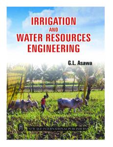
Historical Development Irrigation and drainage development The irrigation area worldwide has increased threefold over the last 50 years, from 94 million ha in 1950 to over 287 million ha in 2007 (Fig. 1.1). Despite this massive increase the irrigated area per member of the world’s population has varied relatively little, from 37.3 ha/thousand people in 1950 to 43.0 ha/ thousand people in 2007, with a peak in the late 1970s of 47.6 ha/thousand people.1 Table 1.1 shows the irrigated area, population and irrigated area per thousand people in a number of countries. The total irrigated area of these 42 countries represents 86% of the total area irrigated worldwide. The countries with the largest areas include India (57.3 million ha), China (53.8 million ha), the USA (21.4 million ha) and Pakistan (17.8 million ha). There are four countries with a significant
irrigated area in the range of 5 to 10 million ha and a further 21 with irrigated areas in the range of 1 to 5 million ha. The irrigated area per thousand people ranges from 2 ha/thousand people in Nigeria to 232 ha/thousand people in Kazakhstan. The generally low level of irrigation development in some subSaharan countries in Africa can be seen from the data for Nigeria, Kenya, Mozambique and Senegal. A valuable assessment of the current situation related to irrigated agriculture and water resources development has been published by the International Water Management Institute (IWMI). The Comprehensive Assessment of Water Management in Agriculture (Earthscan/ IWMI, 2007) was a multi-agency study coordinated by IWMI in association with a number of other organizations, including the Consultative Group on International, Agricultural Research (CGIAR) and the Food and Agricultural Organization of the United Nations (FAO). The Assessment found that agriculture continues to be the largest consumer of water, taking 71% of all withdrawals, compared with 18% for industry and 8% for domestic/municipal use. In total, in 2000, some 3800 km3 of water were withdrawn from surface and groundwater resources, with approximately 2700 km3 being abstracted for irrigated agriculture and 20% of the total abstraction being from groundwater. The dramatic change in the
©Martin Burton 2010. Irrigation Management: Principles and Practices (Martin Burton)
1
Irrigation Management
50 45 40 35 30 25 20 15 10 5 0
Irrigated area (millions ha)
350 300 250 200 150 100 50
Irrigated area
2007
2004
2001
1998
1995
1992
1989
1986
1983
1980
1977
1974
1971
1968
1965
1962
1959
1956
1953
1950
0
Irrigated area/thousand people (ha)
2
Irrigated area/thousand people
Fig. 1.1. Growth of irrigated area worldwide, 1950–2007. (Data from EPI, 2009.)
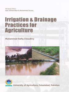
amount of water abstracted for various uses is shown in Fig. 1.2. The total quantity abstracted has increased from around 1400 km3/year in 1950 to around 3800 km3/ year in 2000. As can be seen, the proportion abstracted for municipal and industrial use has changed as the population balance shifts from rural to urban. This shift in the rural–urban population balance has significant consequences for irrigated agriculture. As economic development takes place, the urban population grows and the proportion of the population deriving its livelihood from agriculture (irrigated and rainfed) declines, as does the proportion of the Gross Domestic Product derived from agriculture. The domestic water demands of the urban population increase, as does the demand from the industries2 that provide work for these populations. The political balance shifts, with a focus on protecting the municipal and industrial demands for these growing urban populations. The Assessment found a number of promising and disturbing trends and forces, which are summarized in Box 1.1. Though there are some positive trends, there is much of concern in these findings, with increasing levels of pollution and desiccation of rivers, over-committed river basins, increasing demands from urban populations, and rapidly depleting groundwater reserves.
Water resources development and the changing role of management In many countries irrigation is the main user of water, with over 70% of all abstracted water being used for irrigated agriculture. Water, rather than land, has become the limiting constraint on development, with many basins being closed or approaching closure.3 Figure 1.3 is helpful in understanding how the development of irrigation in many countries has led to this pressure on water resources and how institutional arrangements have adapted to cope with this development. Based on the work of Keller et al. (1998), Molden et al. (2001) identified four broad phases: • • • •
development; utilization; allocation; restoration.
In each of these phases, different needs and therefore different institutional structures exist. In the development phase the amount of naturally occurring water is not constrained and expansion of demand drives the need for construction of new infrastructure, with institutions heavily involved in planning, design and construction of water resources projects. Civil engineers dominate the development process, and as water becomes scarce due to growing demand, additional spare capacity
Introduction
3
Table 1.1. Populations and irrigated areas in selected countries. (From FAO Aquastat website,a http://www.fao.org/nr/water/aquastat/data/query/index.html)
Country
Population (000s)
Average precipitation (mm/year)
Irrigated area (000 ha)
Irrigated area per thousand people (ha)
India China USA Pakistan Iran Mexico Russian Federation Thailand Turkey Indonesia Uzbekistan Italy Bangladesh Kazakhstan Egypt Afghanistan Japan Viet Nam Brazil Ukraine Australia Chile Sudan Greece Philippines South Africa Morocco Nepal Kyrgyzstan Republic of Korea Romania Portugal Sri Lanka Venezuela Algeria Malaysia Nigeria Israel Senegal Mozambique Kenya
1,151,751 1,328,474 302,841 160,943 70,270 105,342 143,221 63,444 73,922 228,864 26,981 58,779 155,991 15,314 74,166 26,088 127,953 86,206 189,323 46,557 20,530 16,465 37,707 11,123 86,264 48,282 30,853 27,641 5,259 48,050 21,532 10,579 19,207 27,191 33,351 26,114 144,720 6,810 12,072 20,971 36,553
1,083 n/a 715 494 228 752 460 1,622 593 2,702 206 832 2,666 250 51 327 1,668 1,821 1,782 565 534 1,522 416 652 2,348 495 346 1,500 533 1,274 637 854 1,712 1,875 89 2,875 1,150 435 686 1,032 630
57,286 53,820 21,400 17,820 8,132 6,256 5,158 5,004 4,983 4,428 4,223 3,973 3,751 3,556 3,422 3,199 3,128 3,000 2,870 2,605 2,545 1,900 1,863 1,594 1,550 1,498 1,484 1,134 1,077 889 808 617 570 570 569 363 293 225 120 118 103
50 41 71 111 116 59 36 79 67 19 157 68 24 232 46 123 24 35 15 56 124 115 49 143 18 31 48 41 205 18 38 58 30 21 17 14 2 33 10 6 3
n/a, data not available. a The database provides information on population and irrigated areas in each country during the period 1993–2007.
is created through the construction of more infrastructure, particularly dams, resulting in step changes in the amount of water available for use.
In the utilization phase the infrastructure is established and the broad goal is to make the most out of these facilities. Creation of additional supplies through further construction
4
Irrigation Management
4000 Withdrawal (km3/year)
3500 3000 2500 2000 1500 1000 500 0 1900
1910
1920
1930
Agricultural use
1940
1950 Year
1960
Industrial use
1970
1980
1990
2000
Municipal use
Fig. 1.2. Change in the water abstracted for human use, 1900–2000. (From IWMI, 2006 after Shiklomanov, 2000 with permission.)
Box 1.1. Emerging Trends (Earthscan/IWMI, 2007) Promising trends • A steady increase in the consumption of food, leading to better nutrition for many and a decrease in famines. The average global energy intake increased from 2400 kcal/capita/day in 1970 to 2800 kcal/ capita/day in 2000, enough to feed the world in spite of a growing population. • A steady increase in land and water productivity, with average grain yields rising from 1.4 t/ha to 2.7 t/ha during the past four decades and significant gains in water productivity. • New investments in irrigation and agricultural water management have the potential to support economic growth within agriculture and other areas. • An increase in global trade in food products and consequent flows of virtual water,a offering prospects for better national food security and the possibility to relieve water stress. Very disturbing trends • The number of malnourished people worldwide remains about 850 million. • The average daily per capita food supply in South Asia (2400 kcal) and sub-Saharan Africa (2200 kcal) remains far below the world average (2800 kcal) in 2000. • Pollution and river desiccation are increasing because of greater agricultural production and water consumption. Fisheries, important for the livelihoods of the rural poor, have been damaged or threatened. • Land and water resources are being degraded through erosion, pollution, salinization, nutrient depletion and the intrusion of seawater. • Pastoralists, many relying on livestock as their savings, are putting grazing lands under pressure. • In several river basins water resources are over-committed and poorly managed, with insufficient water to match all demands. • Groundwater levels are declining rapidly in densely populated areas of north China, India, North Africa and Mexico because of over-exploitation. • Water management institutions have been slow to adapt to new issues and conditions. Double-edged trends • Increasing withdrawals for irrigation in developing countries have been good for economic growth and poverty alleviation, but bad for the environment. • Subsidies, if applied judiciously, can be beneficial to support income generation for the rural, but can distort water and agricultural practices.
Introduction
5
• The growing demand of cities and industries for water offers possibilities for employment and income, but it also shifts water out of agriculture, puts extra strain on rural communities and pollutes water. • Fish and meat consumption is rising, increasing the reliance on aquaculture and industrial livestock production, with some positive well-being and income benefits but greater pressure on water resources and the environment. And emerging forces • The climate is changing, which will affect existing temperatures and patterns of precipitation. Agriculture nearer the equator – where most poor countries are situated – will be affected most. • Globalization continues over the long run, providing opportunities for commercial and high-value agriculture but posing challenges for rural development. • Urbanization increases the demand for water, generates more wastewater and changes patterns of demand for agricultural products, all affecting agricultural practices. • Higher energy prices increase the costs of pumping water, applying fertilizers and transporting products. Greater reliance on bioenergy is affecting food crop prices and water used by agriculture. • Perceptions and thinking about water are changing, with more attention to green waterb resources (in the soil), not just to blue waterc resources (in lakes, rivers and aquifers). • More attention is also being given to ecosystem and integrated approaches and to understanding how forces outside water for agriculture influence both water and agriculture. a
Virtual water is the water used to produce food products. If 1t of grain requires 2t of water to grow, importing 1t of grain is equivalent to importing 2t of water. b Green water is the term applied to water provided by rainfall, stored in the root zone and consumed by natural vegetation and rainfed agriculture. c Blue water refers to the runoff from rainfall, which is stored in lakes, wetlands and aquifers.
activities is constrained, and thus increased attention is paid to water management to conserve water and optimize productivity of available water. In this phase institutions are primarily concerned with management within discrete units for irrigation, water supply, industry, hydroelectric power, etc. In the allocation phase, when closure starts as depletion approaches the potential available water, there is limited scope for further development. Various measures are taken to maximize the productivity of water and managing demand becomes an issue. With little opportunity for making real water savings, reallocation of the available water from lower- to higher-value uses takes place. Institutions are primarily involved in allocation, conflict resolution and regulation, with several management and regulatory functions gaining prominence, such as inter-sectoral allocation and water trading. Coordination between the different, competing interests becomes an issue and moves are made for coordinating river basin management forums to resolve conflict and facilitate management.
In the restoration phase efforts are made to restore the river basin to a balance with its renewable resources. In many cases water is abstracted beyond the renewable resource; this is particularly the case with groundwater where the resource is mined and groundwater levels fall year-on-year. Measures here may include taking irrigated areas out of production and limiting further population growth and industrial development in the river basin. Some technical interventions may be possible in this phase, such as inter-basin transfers, but regulation (particularly enforcement) and management are most prominent. Political involvement is also required where tough decisions are needed to return the basin to a balanced situation. Thus in the early stages of river basin development the focus is on planning and construction of infrastructure to increase the quantity of the renewable resource made available for use. Over time the focus changes to management rather than construction, initially with measures to match supply with the increasing demand (supply management) and later with measures
6
Irrigation Management
Over-abstraction of groundwater
Water resource volume
Renewable water resource
Potentially available water resource
Available water resource
Water resource depleted or used
Time Phase
Development
Level of control
Limited control
Utilization
Allocation
Restoration Full control
Fig. 1.3. Phases of river basin development. (Modified from Molden et al., 2001.)
to limit demand to match the available supply. As noted above, the institutional arrangements and management processes change over time as the pressure on the renewable resources increases. As one approaches the limit of the renewable water resource there is reduced room for manoeuvre and increased risk and consequences associated with periods of drought (Fig. 1.4). The management decisions change from generally top-down development of new infrastructure to more bottom-up approaches, incorporating dialogue with and empowerment of water users. Areas to focus on at this stage in the irrigation sector include education, training and capacity building (of both service providers and water users), development of information systems, institutional reform and organizational restructuring, operations management and performance management in order to keep abstractions to a minimum, reduce wastage, minimize pollution in return flows and increase productivity per unit of water abstracted.
With many rivers approaching closure, management of the water resources, including irrigation, has to improve (see Svendsen, 2005 for a more detailed discussion). Good management is dependent on reliable data, and increasing investment is being made in many countries in strengthening information management systems, particularly in relation to water sharing and allocation and operational management (Table 1.2).
Future Scenarios In addition to assessing the current situation, as summarized in Box 1.1, the Comprehensive Assessment looked at future scenarios, as summarized in Box 1.2. The scenario is relatively bleak from the environmental perspective: with increasing pressure for food some governments will be looking to develop new irrigation areas, possibly on more marginal lands, thereby increasing water abstraction. In addition,
Introduction
7
Management decisions at different phases of development
Construct
Legislate
Enforce
Manage demand
Empower
Renewable water resource (surface and groundwater)
Water resource development
Threats and opportunities: • • • • • • •
Reducing reserve for development Increased risk (from droughts) Climate change Management options constrained Increasing involvement of stakeholders Increasing need for dialogue Increasing need for information dissemination
Areas for action: • • • • • • •
Engagement with stakeholders Re-education of water professionals Re-education of politicians and planners Knowledge management and dissemination Supply management – improved efficiency and productivity of water Demand management, reduction in individual water use Identification of opportunities and mechanisms for changing use (e.g. from irrigated agriculture to domestic or industrial use) • Water trading • Institutional reform in the water sector
Time
Fig. 1.4. Areas for action as river basins approach closure.
any increase in irrigated cropping will result in increased evapotranspiration, raising the water demand by an estimated 60–90% of the current levels. The message is clear and stark: far greater attention and resources will need to be paid to management of the Earth’s finite water resources if we are to both feed the Earth’s population and sustain the aquatic ecosystems.
The Way Forward Those involved with water resources and irrigation development will need to think more broadly, they will need to understand and consider the multiple uses of water and integrate the management and use of these resources. Managers of irrigation schemes will no longer be able to dismiss the impacts of their management on the natural environ-
ment; account will have to be taken of the levels of water abstraction from rivers and groundwater, the impact of agricultural pollutants in drainage wastewater on natural ecosystems. With understanding and knowledge comes an ability to manage better the resource for all uses and users. This understanding will need to be applied to greater appreciation of rainfed agriculture as well, particularly in Africa where farmers often cultivate both irrigated and rainfed crops as part of a mixed farming system. Scheme managers will require greater understanding of and commitment to the needs of vulnerable groups and the poor. Ensuring secure and reliable irrigation water supplies to tail-ends, where these groups are often found, can make a significant difference. Efficiency and productivity need to become keywords for irrigation managers. Efficiency in all operations: such that water abstraction is kept to a minimum, thereby leaving water in the river or groundwater
8
Irrigation Management
Table 1.2. Typical water uses, information uses and users within a river basin. (From Burton and Molden, 2005.) Water uses Watershed water uses
Instream water uses
Extractive water uses
Environmental water uses
Information uses Development and master planning Water sharing and allocation
Operational management
Research Information users Government
• • • • • • • • • • • • • • •
Lakes/reservoirs Forests Natural vegetation Hydropower Recreation Navigation Fisheries Irrigation (surface/groundwater) Potable water (surface/groundwater) Industrial water, including mining (surface/groundwater) Aquatic, wetlands and flood plain environment and ecology Drainage disposal Waste dilution and disposal Repelling salinity intrusions Erosion control
• • • • • • • • • • • • • •
Planning and forecasting Decision making in relation to resource development and protection Resource management and allocation Allocation of water rights Rule formulation Pricing Dialogue with, and among, users Flow control and regulation Flood control, protection and warning Effluent control Monitoring and evaluation (abstractions, effluent levels, environment, etc.) Infrastructure asset management Conflict resolution Water resources, irrigation, environment, ecology, etc.
• Ministries of: Water Resources, Irrigation, Agriculture and Livestock, Energy, Hydrology and Meteorology, Health, Environment and Natural Resources, Fisheries, Forestry, Navigation and Marine Transport, Planning and Development • Legislatures • State, regional or local government • Municipalities Regulatory and • River boards, river basin councils, drainage boards management authorities • Regulatory bodies (rivers, groundwater, environment, etc.) • Courts Companies, groups • Industry (manufacturing, services, mines, forestry, etc.) and associations • Associations (irrigation, rural water supply, environmental lobbies, etc.) • Universities, research centres and training centres • Development agencies and agents • Non-government organizations Individuals • Domestic household users • Irrigation farmers • Livestock owners • Recreators
Introduction
9
Box 1.2. Assessment of the Future (Earthscan/IWMI, 2007) Demand for food • Food demand will rise dramatically in the next 50 years, to almost twice present-day levels. • This demand will be as a result of rising population, but also changing dietary habits with economic development. Diets will change to consumption of cereals, but also to more livestock and fish products. An estimated 25% of the increase will be for grains for livestock feed. Availability of water • The amount of evapotranspiration will increase by 60–90% depending on population growth and the change in dietary habits, increasing from 7200 km3/year today to 11,000–13,500 km3/year in 50 years. • To meet the increasing demand will require: ° using more blue water from rivers and aquifers for irrigation; ° using more marginal-quality water for agriculture; ° using more green water by upgrading rainfed agriculture; ° increasing the productivity of blue and green water to reduce the abstraction; ° managing demand for agricultural water by changing diets and reducing postharvest losses; ° reducing water use in water-scarce regions through trade (importing virtual water).
for the environment, and water is delivered where, when and in the quantity required. Improving scheduling procedures to make better use of rainfall is one way of reducing river or groundwater abstraction, particularly in the humid tropics. Waste needs to be reduced in all parts of the supply chain, whether it is caused by over-irrigation of the farm plot by the farmer, a failure to reduce flows at night in the main systems when water is not required by farmers, or poor storage and loss of harvested crops. The focus needs to change from a narrow perspective on, say canal conveyance efficiencies, to a broader perspective such that as much as possible of the water abstracted for irrigation is converted into useable product at the point of use. In this context proper irrigation scheduling coupled with adequate control and measuring structures may be more relevant than focusing simply on conveyance losses. Productivity will need to improve, though irrigation scheme managers will need to focus on more than just the physical productivity of water (the more ‘crop per drop’ approach). While the physical productivity of water is important, and generally within the control of scheme managers and farmers, consideration needs to be taken of the economic water productivity (the value of agricultural water production per unit of water) and
the agricultural water productivity (the net gains from all uses of water for agriculture, including crops, fisheries, livestock, forestry, firewood, etc.). Improving these facets of productivity will involve improving the support given for inputs and supporting processes other than irrigation water and drainage water removal, such as credit, input provision, agricultural machinery and marketing. With the increasing pressure on land and water resources to produce increasing quantities of agricultural produce, the need for better educated, informed and motivated managers in the irrigation sector is evident, whether they are the head of an irrigation district, the manager of an irrigation scheme, the executive director of a water users association or a farmer. Reforms are taking place in many countries through the process of irrigation management transfer, giving more rights and responsibilities to water users for the management, operation and maintenance of all, or parts of, their irrigation and drainage systems. In many countries these changes need to be matched by reforms to state agencies responsible for water resources and irrigation development and management, and correspondingly in the education and training institutions that feed young professionals into these agencies and the sector in general. As Robert Chambers advocated in the 1980s (Chambers, 1988; Box 1.3), a new cadre of irrigation managers is required, with enhanced
10
Irrigation Management
Box 1.3. On Irrigation Managers None of these measures for bureaucratic reorientation, as it has been called, could in itself reform canal irrigation management. Nor would it make sense to recommend implementing them all simultaneously. As always, the best mix and sequence depends on conditions. As more is known, through more research and writing, about the real world of managers, so also it will become clearer what best to do. Exhortation or moralising are unlikely to make much difference. The conditions, motivation and incentives of the managers are the key. And among these, professional methodologies and behaviour present one promising point of attack. If it is clear what managers should be doing, it will be easier for them to do it; which brings us to what they and others can do – diagnostic analysis of existing canal irrigation systems, and selected actions to improve performance such as making and implementing operational plans. (Chambers, 1988)
knowledge, skills, status and remuneration for the important work that they do. The irrigation manager in the 21st century will need to: •
•
•
•
•
understand the wider agricultural and water resources issues associated in using water for agriculture; understand the importance and value the natural ecosystems within which irrigated agriculture lies and upon which it depends; manage irrigation systems to provide reliable, adequate, timely and equitable irrigation water supply, and associated drainage water removal; manage water, in all its forms, to the benefit of all communities and the natural ecosystem; understand and accept the concept of service provision, and the need to liaise and work with water users in the provision of a responsible and fair service in
•
•
return for timely and adequate payment of the service fee; understand the wider dimensions of irrigated agriculture, from catchment management through to marketing, and work towards enhancing efficiency and productivity in all parts of the supply chain; understand and treat irrigated farming as a business, to which the supply of irrigation water and removal of drainage water in a reliable, timely and adequate manner makes a significant contribution to the success or failure of the enterprise.
It is hoped that the information provided in this book will assist in addressing these issues and contribute to developing the necessary understanding, knowledge and skills required for effective and productive management, operation and maintenance of irrigation and drainage schemes.
Endnotes 1
Data compiled by the Earth Policy Institute (http://www.earth-policy.org/index.php?/datacenter/xls/book_ pb4_ch2_8.xls) using data from the Worldwatch Institute, the FAO and the United Nations Population Division. 2 These demands are not just the abstracted water quantities; they will include increased minimum flow requirements to dilute the wastewater being discharged by these industries. 3 A basin is considered closed when all available water has been used. A basin remains open when there are water resources remaining to be developed or used.
2 Components of Irrigation and Drainage Systems
Irrigation and drainage is a complex mixture of technical, institutional, economic, social and environmental processes. This chapter outlines the different elements of these processes and how they interact.
Overview Chambers (1988) identified irrigation and drainage schemes (I&D schemes)1 as a complex mixture of physical, human and bioeconomic domains. Figure 2.1 outlines these domains, the activities involved and their interactions. In the physical domain we are dealing with the climate, soils and physical infrastructure. In the human domain we are dealing with the irrigation agency personnel and with farmers, their families and other stakeholders. In the bioeconomic domain we are dealing with the crops, livestock and markets. Overlying these three domains are the political, economic and legal domains. Those involved with irrigation development need to be aware of, and understand, all these domains, and know which factors they can control and which are out of their control and influence. Politicians and government officials, for example, have control over the political, economic and legal domains, and have the ability to set the direction in terms
of political input, legislation and economic policy to support the irrigated agriculture sector. Managers of irrigation systems have control over the physical domain, and can organize the capture and distribution of water. Within the human domain the irrigation staff are under the control of the system manager, while the farm households and labour are under the control of the water users themselves. The bioeconomic domain is influenced by the market and government policies, such as for subsidies and food pricing. Using a systems approach, Small and Svendsen (1992) separated the various components involved in irrigated agriculture into a series of nested systems (Fig. 2.2). The systems approach focuses on the inputs, processes, outputs and impacts at different levels. The nested system begins with the outputs of the irrigation and drainage system (I&D system) (supply of water to crops) feeding in as one of the inputs (along with the land, labour, seed, fertilizer, etc.) to the irrigated agriculture system. The outputs in the form of agricultural production from this system feed into the agricultural economic system and with other inputs (traders, market price, etc.) provide inputs (incomes) into the rural economic system. Together with other income, such as off-farm labour, and expenditure, the rural economic system feeds into
©Martin Burton 2010. Irrigation Management: Principles and Practices (Martin Burton)
11
12
Irrigation Management
Irrigation/ drainage system boundary
Physical domain CLIMATE
re
u pt
er
ca
at
Human domain
W
TRANSFERS
es
Irrigation staff/Water users associations
Ou
In
t
Se
rv
ice
fe
Farm households and labour
Rain
Main system infrastructure
Irrigation water supply to tertiary unit On-farm water management
La
bo
ur
Fo
r
ate
dw
un Gro
od Crops, livestock, etc.
MIGRATION
ts
h
Cash
Inpu
as
Sale
C
MARKETS Bioeconomic domain
Fig. 2.1. Domains related to irrigated agriculture. (Adapted from Chambers, 1988.)
the politico-economic system to deliver national development objectives. Building on the above and other work, a useful categorization of domains in relation to irrigated agriculture is: • • • • •
technical; institutional; economic; social; environmental.
Technical covers the physical infrastructure related to I&D systems, the canals, drains, roads, field layouts, etc., and includes analysis of the physical environment to facilitate
the design, construction and implementation of the I&D system. Institutional covers the political, legal and organizational frameworks influencing irrigated agriculture, while social covers the interaction of people within the irrigation schemes and the ways that they live and work together. Economic covers the financial and economic aspects of irrigated agriculture, the cost and value of inputs, resources and outputs. Finally, environmental covers the physical environment impacted by the scheme and the health issues related to I&D systems. Table 2.1 summarizes some of the components in each of these domains, while more detail is given in the following sections.
Components of Irrigation and Drainage Systems
6
13
6
Politico-economic system 5
5
Rural economic system 4
4
Agricultural economic system 3 Irrigated agriculture system 2
Irrigation and drainage system
3 2
1
Other inputs
Other inputs
Inputs/outputs to each system 1 Operation of irrigation facilities
3
Agricultural production
5
Rural economic development
2 Supply of water to crops
4
Incomes in rural sector
6
National development
Fig. 2.2. Irrigation and drainage functions in the context of nested systems. (From Small and Svendsen, 1992 with permission.)
Table 2.1. Outline of components within each domain. Domain
Component
Technical
• Physical conditions related to design and operation (climate, topography, soil, water resources) • Physical infrastructure (irrigation and drainage systems, roads, housing, etc.) • Political system • Legal framework • Organizations and organizational structures and functions • Markets • Market price • Development and operational costs • Economic development and livelihoods • Employment opportunities • People • Communities and social structures • Social norms (religion, attitudes, patterns of behaviour) • Impact on the water environment (downstream flows, water quality) • Waterlogging and salinity • Health issues
Institutional
Economic
Social
Environmental
14
Irrigation Management
Technical Domain The technical domain for I&D schemes covers both physical aspects and the technical processes involved in developing the scheme. The physical components of an I&D scheme are shown in Fig. 2.3. The main components from the water management perspective, starting from the field level and working up to the water source, are summarized in Table 2.2. A more detailed breakdown of the physical infrastructure components for I&D systems is outlined in Table 2.3. The various structures that exist in an I&D system can broadly be divided into conveyance, control and ancillary. Conveyance structures include siphon underpasses, culverts and aqueducts, while control structures include cross and head regulators, and measuring structures. Ancillary structures comprise bridges, access points, bathing points, etc. Control structures form an important part of the operation of the irrigation system as they are the means by which water is managed and distributed in a controlled and regulated manner according to need.
Institutional Domain The institutional domain covers the political, legal and organizational aspects related to irrigated agriculture. Politics and politicians play a large part in irrigation development and irrigated agriculture, as agricultural production and rural livelihoods are key areas of political interest. This interest can be either beneficial or harmful depending on the context. Political support for the irrigated agriculture sector can result in measures to improve availability of inputs, access to markets and market prices. It can also be beneficial in allocating funds, either for capital investment for new schemes or rehabilitation of existing schemes, or for scheme management, operation and maintenance. Strong political support is also required to introduce, revise or update legislation, particularly in relation to the transfer of the management of I&D systems to water users associations (WUAs). In this context
political influence can be harmful where politicians interfere in the setting and levying of irrigation and drainage service fees, either by setting an unreasonable cap on the service fee that can be levied, or by suggesting during election periods that water users need not pay such service fees. In essence, a strong irrigation sector depends on strong and consistent political support; where this support is missing or muted it is likely that the irrigation sector will have difficulties, principally in adequately funding the management, operation and maintenance of I&D schemes. The irrigation sector is usually covered by legislation in the form of all or some of the following: Water Resources Law, Irrigation and Drainage Law, Water Users Association Law, Public Health Law, Environment Law, Tax Code, Civil Code and Employment Law. The water resources legislation covers the abstraction and use of water resources (Fig. 2.4), while the irrigation and drainage legislation covers the use of these water resources for irrigation and the drainage of agricultural lands. WUA legislation is more recent and covers the establishment of water users associations, and will involve changes in the water resources, irrigation and drainage legislation and the tax code. Public health and environment legislation generally relates to the impacts of irrigation and drainage, and will look to control its adverse impacts through regulation on wastewater discharge, pollutants, limiting of standing water, etc. The tax code will detail the tax regulations related to the irrigation and drainage sector, and is of particular interest to water users associations in terms of whether they have to charge sales tax (VAT) on the services they provide, and property tax on the infrastructure assets. The civil code and employment legislation are generally applicable within society. The number of organizations involved in irrigated agriculture, their structure and functions have significant bearing on irrigated agriculture. The types and functions of organizations involved vary from country to country, but generally include the following: • •
Ministry (or Department)4 of Agriculture; Ministry (or Department) of Water Resources;
Rainfall
River
Urban centre Intake headworks Primary canal Pump station trickle
Hand move
Roads Storage
Village area
Housing
Alfalfa valve
Market
Drip Long basin
Land prep Field
Lateral move
Basin to Furrow
Water table
Field
Border strip
Soil
Crop
Wetting front
Buried drains
Fertilizer
Components of Irrigation and Drainage Systems
River diversion works
Main drain
Capillary rise Root zone
Fig. 2.3. Physical components of an irrigation and drainage scheme. 15
16
Irrigation Management
Table 2.2. Physical components of an irrigation and drainage scheme. Component
Explanation of role
Crop
The end product of the farming and water management activity. Determines the quantity and timing of irrigation water requirements The storage reservoir for irrigation water. The greater the storage capacity, the greater the interval that is possible between irrigations. The depth of the root zone is determined by the type of crop and its rooting characteristics The soil texture determines the water-holding capacity of the soil and its permeability. Heavier soils, such as clay, hold more water than lighter soils, such as sand. As a result, in general, lighter soils need irrigating more frequently than heavier soils The depth to groundwater can influence the irrigation needs of the crop. If the groundwater is within 1–2 m of the soil surface there may be a contribution to the crop’s water needs from groundwater, thus reducing the demand for irrigation. If the groundwater level is too high (<1 m) it will cause waterlogging and salinization, and reduction or loss of crop yield The climatic conditions drive the evaporation of water from the soil surface and the transpiration of water from the crop. Evapotranspiration increases with temperature, wind speed, lowering of the relative humidity and sunshine hours (day length). Irrigation is required to replace the water lost to evapotranspiration The field layout and irrigation method influences the efficiency and uniformity of irrigation. Various factors influence the choice of irrigation method, including the crop type, soil type, streamflow rates and topographic conditions, including land slope and topographic uniformity. Cost is also an important factor in determining the irrigation method The field size influences irrigation management. Smaller field sizes generally mean more variation in the pattern of irrigation demand and increase the planning and management that is required to schedule and supply irrigation water Irrigation water is conveyed to the fields by the tertiary and quaternary or field canals. The type and condition of these canals (lined, unlined, piped, well/poorly maintained) influences the losses from the canals Open (surface) drainage channels remove excess irrigation and rainfall from the fields and ensure that the soils are adequately drained. Subsurface (closed pipe) drains discharging into open drains are used to regulate groundwater levels below the crop root zone Control structures are required to divide and regulate the discharges entering each canal. Lack of control structures within the tertiary unit restricts the ability to manage the supply of irrigation water to match demands Measurement of irrigation supplies is required to know how much water is being delivered and to assess if the supply is adequate or excessive in matching the crop needs Main system canals, comprising primary and secondary canals, convey irrigation water to the tertiary units Main system drains (primary and secondary) collect drainage water from the tertiary unit drains and dispose of it into natural drainage channels (streams, rivers, lakes and the sea)
Root zone
Soil
Groundwater
Climate (sunshine, temperature, rainfall, etc.)
Field layout and irrigation method
Field size
Tertiary unit2 irrigation channels
Tertiary unit drainage channels
Tertiary unit control structures
Tertiary unit discharge measurement Main system3 canals Main system drains
Continued
Components of Irrigation and Drainage Systems
17
Table 2.2. Continued Component
Explanation of role
Main system control structures
Control structures, such as gated cross and head regulators, are required to regulate the flow entering each canal, while measuring structures are required to determine the amounts delivered. Without functioning control structures it is not possible to closely match irrigation supply with irrigation demand Conveyance structures, such as inverted siphons and culverts, are required to pass the irrigation canal over or under natural or man-made obstructions The nature of the water source has a significant influence on water management. The pattern of flow in the river controls the cropping pattern within the irrigated area. The quantity of water can influence the water management activity; in water-short systems water management is generally more carefully performed than in systems with adequate water supplies In the river, main system, tertiary unit or field, providing storage for a variety of durations: over-year, within-year, within-season, weekly, daily, overnight, etc.
Main system conveyance structures Water source
Storage reservoirs
Table 2.3. Physical infrastructure of irrigation and drainage systems. Component
Level(s)
Purpose
Reservoir
River Main canal
Flood bunds Canals
River Primary Secondary Tertiary Quaternary Primary Secondary On-farm Main canal Main canal Main drain Main canal
To store water for the irrigation scheme, either on the river or in the system. The river reservoir may also be built to help alleviate flooding in the scheme To protect the scheme from flooding To convey water. They may be open channels or closed pipes
Drains (open and closed) River weir Pump station Headworks
Sediment excluder or sediment trap Cross regulator Head regulator Measuring structure Aqueduct Culvert
Main canal
To remove surplus water from the field. Surface flow protection drains may be required to protect infrastructure from upslope runoff To divert and control irrigation supplies To lift water to command level for irrigation. To remove water from drainage channels that are below river level To control the inflow to the main canal. Comprises a gate and usually a pipe to throttle the flow and thus limit inflow in flood periods To exclude or trap silt, which is then returned to the river by flushing or mechanical removal To raise and maintain the water surface at design elevation
Primary and secondary canals Primary, secondary To regulate discharge entering a canal and tertiary canals Primary, secondary To measure discharge for operational purposes and tertiary canals All levels of canal To pass canal over an obstruction (another canal, a drainage channel, etc.) All levels of canal To pass the canal or drain under an obstruction (road, or drain drainage channel, etc.) or to pass cross-drainage flow under a canal
Continued
18
Irrigation Management
Table 2.3. Continued Component
Level(s)
Purpose
Super-passage
Main canals
Drop structure
All levels of canal or drain All levels of canals
Used to pass flood flows and associated sediment over main canals To lower the canal or drain bed level in a safe manner. Used to reduce canal or drain gradients on steep land Used to escape water from a canal into the drainage network in the event of oversupply or underutilization, or for emergencies (e.g. a breach in the canal downstream) Used to pass the canal below an obstruction, such as a road or drainage channel Simple distribution structure to distribute the water between tertiary and quaternary canals Reservoir to store irrigation water during the night. Main canals can operate 24 h/day, while lower-order canals can be operated during the daytime only. On-farm storage reservoirs allow the farmer to take water as delivered and then use it when needed Abstraction of groundwater for irrigation. Often used in conjunction with surface water system To allow human and animal traffic over the canal or drain
Escape structure
Inverted siphon underpass Distribution box
All levels of canals
Night-storage reservoir
Tertiary canal Quaternary canal Main canal or on-farm
Tubewell, open well
On-farm
Bridges and culverts Road bridges Foot bridges Access points Main canals Roads
Inspection roads Access roads
Fields
Within tertiary unit
Villages
Throughout the scheme
• • • • •
Access points into the canal for human and animal traffic for obtaining water, washing, etc. To gain access to the irrigation system, fields and villages. Also for inspection and maintenance alongside canals and drains Prepared land to cultivate the crop. Laid out for different methods of irrigation (basin, furrow, sprinkler, etc.) Living space for the farming community. The distance from the village to the fields is important
Ministry (or Department) of Irrigation and Drainage; Ministry (or Department) of Environment and Natural Resources; Ministry (or Department) of Public Works; Ministry of Finance; Regional and Local Government.
The roles of these different organizations in relation to river basin and irrigation management in Mexico are illustrated in Fig. 2.5 in terms of the functions that they each perform. Such organizational mapping can be extremely helpful in understanding the different functions and linkages. Irrigation management depends on both physical and human resources. The two are tightly interrelated; good infrastructure with poor management will not deliver reliable,
adequate and timely water supplies. The human resource is a key aspect of good irrigation management; a good irrigation manager and his/her team can achieve a considerable amount, even though the physical condition of the irrigation and drainage network might not be so good. The key actors involved in irrigation and drainage management, from the field to the water source, are summarized in Table 2.4.
Economic Domain Irrigation and drainage development in general contributes to improved livelihoods and economic development. The greater reliability of water supply provided by irrigation systems over rainfed agriculture results in higher
Land Reclamation Cadastre Water Use and Wastewater Licences; Water Supply Contracts
National Water Resources Monitoring System
Water Use Register
Wastewater Discharge Register
Registers National Water Cadastre
Hydraulic Infrastructure Register: National Water Strategy
• • • •
Dams/reservoirs Irrigation Water supply Flood protection
Plans Water Resources Protection measures for: • Human health and safety • Livestock watering • Groundwater • Surface water • Aquatic environment
River Basin Plans
Protection measures
• • • • • • •
Protection from: Droughts Flooding Pollution Mud flows Erosion Low flows Over-abstraction
Wastewater Discharge Authorization/Licence
Permissions/ authorization Annual Water Supply Agreements
Gravel Extraction Authorization/Licence
19
Fig. 2.4. Typical elements of water resources legislation.
Extraction Discharge Authorization/Licence: • Surface • Groundwater
Components of Irrigation and Drainage Systems
National Flood and Drought Information and Warning System
Information systems
20
Enforce quality
Monitor quality
Operate/maintain facilities
Allocate/distribute
Plan (basin-level)
Ensure quality
Monitor quality
Maintain facilities
Construct facilities
Withdraw/distribute water
Allocate water
Plan (basin-level)
Protect environment
Protect against flooding
Construct facilities
Wastewater
Groundwater
Ensure quality
Monitor quality
Maintain facilities
Construct facilities
Distribute water
Allocate water
Key players
Plan (basin-level)
Surface water
Ministry of Environment CNA National Headquarters Irrigation Management
CNA Regional Office River Basin Council CNA State Office State Water Commissions CNA Irrigation District Office WUAs Irrigation Districts WUAs Irrigation Units Aquifer Management Councils (COTAS) Municipal Water Supply Utilities Industries NGOs Irrigators
°
Fig. 2.5. Essential basin management functions and key actors in the Lerma Chapala River Basin, Mexico. ● indicates activity; indicates limited activity; CNA, National Water Commission; WUA, water users association; NGO, non-government organization. (Modified from Burton et al., 2002; Wester et al., 2005.)
Components of Irrigation and Drainage Systems
21
Table 2.4. Management components of irrigated farming systems. Farmer
Water Master5 (within the tertiary unit/on-farm)
WUA O&M Engineer/ Technician WUA management
Water Master (main system)
Main system service provider staff
O&M procedures
Setting and collecting service fees
The capability of the farmer has a significant influence on irrigation water management. A good farmer will know when and how often to irrigate and will apply the correct quantity of water to match the crop and soil needs The water master is a central figure in water management within the tertiary unit, organizing and overseeing the distribution of water between farmers. A good water master can have a very beneficial impact on the productivity and efficiency of water use The WUA O&M engineer/technician will work with the water master to plan and schedule irrigation water, and monitor its distribution. The better the planning and monitoring, the better the implementation The WUA management can influence performance in relation to irrigation water management by monitoring the planning, allocation and use of irrigation water, and in setting the standards required As at the tertiary unit/on-farm level, the main system water master is a key figure, responsible for the day-to-day distribution of water to tertiary units. A good water master can have a significant impact on system performance; it is important that they are well trained and well motivated As with the water master, the staff of the main system service provider can strongly influence the performance on an I&D system. The more professional and motivated the staff, the better the water delivery performance The O&M procedures, both within the tertiary unit and at the main system level, influence the performance of irrigation water management. Well-organized and systematic procedures lead to more efficient and productive water management With an increasing focus on I&D systems being financially self-reliant, the setting and collection of the service fees is growing in importance. Management systems for setting, collecting and utilizing the service fee need to be transparent and accountable
WUA, water users association; O&M, operation and management; I&D, irrigation and drainage.
crop yields, greater levels of production and increased income when the produce is sold. In poor areas irrigation can make a significant contribution to poverty reduction and provision of basic foodstuffs for families. In general, irrigated agriculture requires more labour than rainfed agriculture, resulting in increased employment opportunities for landless labour. As a result of the increased productivity, secondary industries develop, including traders, shopkeepers, agricultural machinery repair workshops and the like. It is important to distinguish between the economic costs and benefits of irrigation and drainage development and the financial costs and benefits. The economic analysis looks at the benefit to society and government in general, while the financial analysis looks at the actual monetary transactions that take place. Economic analysis will take
account of the benefits of creating employment, of developing secondary industries, of increasing demand for processed goods and the like. The financial analysis can be carried out for the operating authority and for farmers. For the operating authority it will look at the costs required to run the organization and provide its services, and the sources of income to cover these costs. For farmers it will look at the income generated for the farmers and their families as a result of the scheme. In general terms the government and any financial backers of the development will be interested in the economic costs and benefits, while the operating authority and farmers will be interested in the financial costs and benefits and whether the scheme can pay its way and improve the farming family’s standard of living and food security.6
22
Irrigation Management
Allied to the potential financial benefits arising from irrigated agriculture are increased costs to cover the expenditure required to manage, operate and maintain the I&D system. Unfortunately governments and farmers in many countries are still reluctant to cover the real costs of managing, operating and maintaining these systems (MOM costs) despite the obvious financial and social benefits arising from them. For the last 20 years, significant sums of money have been invested in rehabilitating I&D systems, only for them to fail again several years later due to inadequate investment in maintenance. In an effort to overcome the difficulties of adequately funding management, operation and maintenance, some governments have transferred the management of the schemes or parts of the schemes to the water users, in the belief that as the direct beneficiaries they will be willing to cover the real MOM costs. However, despite being prepared to cover the costs of seeds, machinery hire, fuel and the like, farmers in some countries still have difficulty in accepting that they should pay the real cost for providing irrigation water and drainage water removal. This is one of the biggest challenges facing the irrigation and drainage sector.
Social Domain Farming within I&D schemes requires more social cohesion, cooperation and discipline than rainfed farming. Water users need to collaborate to share the available water supplies; in many systems fairness or equity of allocation and distribution is valued more highly than adequacy of supply.7 In general, where the social cohesion is strong irrigation is productive, while where the social cohesion is weak irrigation suffers. Successful traditional hydraulic societies, such as the Chagga on Mount Kilimanjaro, some hill tribes in Nepal and the Balinese with their Subak irrigation, have long-standing social norms and rules for irrigation, to which all users subscribe. This ability to work together and enforce compliance with a set of agreed rules is not apparent in all I&D schemes, and becomes more difficult to engender the
larger the scheme becomes. In the larger schemes the social domain will encompass the management and staff of the organization responsible for managing the main system as well as the farming community. The nature of the relationship between these two social groups will have a direct bearing on the nature and quality of the service provided. Where there is corruption and/ or lack of transparency the service delivery may be good to some farmers but poor to others, with high levels of distrust between the two groups. Where there is accountability, openness, trust and communication between the two groups service delivery will be measurably better, and productivity consequently higher.
Environmental Domain Interest in the environmental domain focuses on the impacts of irrigation and drainage development on the natural environment, as well as the potential impact of external factors on the scheme. The impacts of the scheme on the environment are generally most extreme when the scheme is first developed, though poor operation can be very harmful, particularly in the excessive abstraction and application of irrigation water and/or excessive use of pesticides and fertilizers. The main environmental impacts include (Table 2.5): • • • •
land degradation within the scheme; degradation of water quality, both in surface and groundwater; groundwater depletion; ecological degradation.
As can be seen from Table 2.5, responsible management can help to significantly reduce the adverse environmental impacts of I&D schemes. In summary such measures include: •
•
keeping river and groundwater abstraction to an absolute minimum by efficient operation and effective maintenance of the system; keeping drainage water flow to an absolute minimum through controlled application of irrigation water;
Table 2.5. Impact of irrigation and drainage development on the environment. (Modified from ICID, 1993; Neville, 1996.) Impact Hydrological impacts Low flows in river Flood regime
Lowering of groundwater table
Raising of groundwater table Water quality impacts Solute dispersion
Toxic substances
Agrochemical pollution
Mitigation measures
Abstraction of water for irrigation can have negative impacts on the downstream aquatic environment and downstream users Uncontrolled flooding can cause damage to the human environment, but can be a central part of natural flood plain ecosystems, especially in recharging wetlands. Cutting off the natural floods can also adversely affect fish migration The manner in which dams are operated has a significant impact on the downstream environment. Reservoirs can have adverse impacts in relation to human health (malaria, schistosomiasis, etc.) Depletion of groundwater can have serious implications for the environment, leading to saltwater intrusion, land subsidence, drying out of wetlands, acidification of (sulfate) soils and exposure of toxic layers (arsenic). In extreme cases, such as with fossil aquifers, the aquifer can dry up completely if overabstracted One of the most common long-term impacts of irrigation, caused by over-irrigation. A rising groundwater table leads to waterlogging and salinization, loss of crops, loss of productive land and health risks from standing water
Minimize abstraction through efficient scheme operation. Adjust cropping pattern to minimize abstraction during low-flow periods Operate dams and river weirs to allow passage of (controlled) flood flow at critical times. Maintain connectivity of the river with the flood plain and wetlands
Limit groundwater abstraction through licensing of boreholes and regulation and control of abstraction quantities
Good irrigation management, especially at the field level, to minimize water application losses. Provision of adequate drainage system
Minimize water abstractions. Allow (controlled) flood flows at critical periods Implement responsible regimes for pesticide use. Minimize irrigation application losses. Implement flushing procedures for salts at high-flow periods Implement responsible and informed fertilizer application regimes. Educate farmers in the proper use of fertilizers and pesticides. Minimize application losses from fields
Continued
23
Reduced flows in a river can reduce the river’s ability to dilute and treat water-soluble pollution. Reduced flood flows in wetlands can lead to a build-up of pollutants and salts Irrigation can flush out toxic substances in the soils, leading to adverse downstream impacts. Pesticides are particularly dangerous for the environment Though beneficial to irrigated crops, natural and chemical fertilizers can be harmful to the environment. Nitrates are soluble, while phosphates can fix to soil particles and be transported by erosion, resulting in harm to aquatic life and algae growth. Nitrates in water are harmful to human health
Operate the dam in consideration of the environmental impacts. Allow (controlled) flood flows, variation in water levels, minimum low-flow regimes
Components of Irrigation and Drainage Systems
Operation of dams
Explanation
24
Table 2.5. Continued Explanation
Mitigation measures
Anaerobic degradation
Anaerobic conditions can be brought about by high levels of nutrients or decomposition of organic matter (such as in reservoirs), leading to emission of greenhouse gases (methane, hydrogen sulfide, ammonia)
Minimize nutrient runoff from irrigation schemes. Clear new reservoir areas of vegetation prior to filling
Build-up of salts in soils may be caused by salts brought in by irrigation water, capillary rise from saline groundwater, or solutes leached from natural or artificial fertilizers Soil properties can change with irrigation or drainage. Drained peat soils can degrade rapidly, clay soils with high sodium-ion content (alkaline soils) can lead to collapse of the soil structure Over-irrigation and leaching of salts into the groundwater is a common problem in some localities Drainage systems pick up drainage water, which can have five to ten times the salt concentration of the irrigation water
Manage the salt balance in the irrigated soils and provide adequate drainage so that salts do not build up. Implement responsible leaching regimes Understand the behaviour of soils and manage them responsibly. Apply gypsum to alleviate problems with alkaline soils Manage irrigation water application to minimize losses. Provide drainage to avoid build-up of salinity levels Dispose of the drainage water responsibly, to the sea or a sink if high levels. Manage the salt balance to avoid build-up of salts over time Maintain minimum-flow regimes in rivers and limit groundwater abstraction
Soil quality impacts Soil salinity
Soil properties
Saline groundwater Saline drainage water
Saline intrusion
Reduced river flows and/or reduced groundwater flows can lead to saline intrusion in coastal areas, adversely affecting groundwater-based drinking water and the coastal/estuarine aquatic environment, particularly mangrove swamps
Erosion and sedimentation impacts Local soil erosion Soil erosion on fields can lead to the loss of good topsoil and have adverse impacts on the downstream ecology
Hinterland degradation
River morphology
Design I&D system appropriately; align furrows, borders, etc. to minimize soil erosion. Manage the land appropriately; keep vegetative cover during rainy periods. Design drains to avoid gullying The increased population supported by an irrigation scheme may lead Identify possible impacts during design and implementation. Build to increased erosion as a result of tree-cutting for fuel wood, fuel wood plots on the scheme, allow for growing fodder for livestock grazing, etc. livestock, etc. Altering the natural flow regime of the river by construction of dams Where possible, design structures to pass sediment loads and weirs can lead to sediment deposition upstream and downstream aggradation of river beds downstream of structures
Irrigation Management
Impact
Sedimentation
Estuary degradation
Sedimentation in reservoirs can significantly shorten their lifespan, Implement soil erosion measures upstream of reservoirs to leading to the need for more storage elsewhere and thus maintain vegetative cover. Keep sediment out of irrigation impacting the environment. Sediment in irrigation canals reduces systems with sediment basins, vortex tube silt extractors, etc. capacity Design and operate canals to maintain flow velocities and carry sediment to fields Loss of natural sediment in rivers can lead to degradation of estuaries Design and operate structures to pass sediment load and associated aquatic ecosystems dependent on the sediment downstream
Water bodies
Degradation of surrounding area Valleys and shores
Wetlands and plains
Pests and weeds
Animal diseases Aquatic weeds
Assess the local environment at the planning and design stage and allow for mitigation measures to protect wildlife, migratory routes, traditional grazing, etc. Existing water bodies will be affected by irrigation and drainage Identify mitigation measures at planning stage and apply at development (rivers, wetlands, flood plains, etc.) and new bodies design and implementation stage. A variety of measures will created (reservoirs, canals, drains, storage ponds, etc.). be required Waterborne disease may increase The increased population supported by an irrigation scheme can Consider possible impacts during design and implementation. have adverse impacts on the local environment, through Build fuel wood plots on the scheme, allow for growing fodder tree-cutting for fuel wood, livestock grazing, etc. for livestock, etc. Traditional flood plain and estuarine ecosystems may be adversely Identify mitigation measures at planning stage and apply at affected by flood attenuation and water abstraction design and implementation stages. Minimize abstraction, maintain partial flood flow regimes and minimum low flows Includes marsh, fen or peat land with areas of standing fresh or Identify wetlands and associated ecosystems at planning stage, brackish water. Wetlands (including mangrove swamps) are very assess impact and formulate and apply mitigation measures. vibrant and productive ecosystems, in supporting both aquatic Drainage of wetlands is nowadays not considered to be ecosystems/wildlife and humans (fishing, etc.) justified on environmental grounds Adopt measures to avoid certain types of pests and diseases, such as avoiding monocropping Adopt measures to mitigate contact of livestock with potentially harmful water bodies Can be a major problem in some areas. Need to adopt management and maintenance measures to control the spread of aquatic weeds. Use of herbicides can be very harmful to the aquatic environment Continued
25
Some pests and weeds benefit from development of I&D schemes. Natural predators such as snakes, birds and insects may be reduced by pesticides and land-use changes Animals are subject to waterborne disease, and may be adversely affected in an I&D scheme An I&D scheme can provide an ideal habitat for aquatic weeds. The capacity of reservoirs and canals can be seriously impeded by aquatic weeds such as water hyacinth, taifa reed, etc. Vegetation in canals/drains is a habitat for disease vectors such as snails and mosquitoes
Components of Irrigation and Drainage Systems
Biological and ecological impacts Scheme area land use Development of an irrigation scheme will radically alter the human and ecological environment of the area
26
Table 2.5. Continued Impact
Explanation
Human health
I&D schemes can have serious adverse impacts on human health. An extensive public health programme can help considerably in Malaria, Japanese encephalitis, schistosomiasis (bilharzia), reducing the incidence and impact of these diseases. A variety lymphatic filariasis and onchoceriasis (river blindness) are carried of measures is required, such as use of mosquito nets at night, by mosquitoes and other waterborne vectors public hygiene measures, and operation and maintenance measures such as maintaining flow rates in canals and preventing the occurrence of standing or stagnant water
Socio-economic impacts Population growth Irrigation schemes generally increase the population density in an area and can stimulate other economic development and growth. This can have a variety of impacts on the locality Development of irrigation schemes can change the levels of income and the balance within the local community, for example for fishers and pastoralists
Human migration
Human migration into an area as a result of work (e.g. as cotton pickers, farm labour) can alter the balance of the local society Resettlement of communities living in areas to be flooded by reservoirs and in lands to be irrigated can be traumatic for those affected In some cases women have been adversely impacted by irrigation and drainage development, with increased workloads from more intensive farming Pastoralists often lose out as a result of irrigation and drainage development, as do fishers If irrigation and drainage development is successful if may affect the local economy, increasing the price of labour and reducing local prices due to greater availability of agricultural produce Irrigation and drainage development can increase the opportunity for recreation, particularly bathing in reservoirs and canals. In some locations there may be significant health risks, for example with schistosomiasis
Resettlement
Gender issues
Vulnerable groups Regional impacts
Recreation
I&D, irrigation and drainage.
Not always possible to predict the nature of the changes that may take place. Design of settlements and associated facilities, such as sewage treatment, can help mitigate impacts It is important to identify all the stakeholders in irrigation and drainage development and to allow for the needs of each. For example, where fishers lose the previous ability to fish in the flood plain, they may benefit from fishing in the reservoir A social impact assessment can be a useful part of the planning process Adequate planning for resettlement and consultation with those affected can mitigate the impacts A social impact assessment is required to understand the potential impact and mitigation measures for all stakeholders, but particularly for women and vulnerable sections of society As above, identify the groups and the issues they face and formulate mitigation measures The socio-economic analysis of the project should identify possible impacts, and the nature of the costs and benefits Where waterborne diseases are a potential risk, settlements should be located away from canals and night-storage reservoirs to prevent children using them as swimming pools
Irrigation Management
Income and amenity
Mitigation measures
Components of Irrigation and Drainage Systems
•
•
•
•
minimizing the level of pesticide and fertilizer in drainage water though controlled application and controlled irrigation; controlling application of irrigation water at field level to avoid over-irrigation contributing to rising groundwater levels and subsequent salinization of the land; reducing losses from irrigation canals through measures such as canal lining and timely maintenance; reducing health risks through a knowledge and application of measures to alleviate health risks, such as avoiding areas of standing water (for mosquito control) and health education for farmers and their families.
Phases of Development As noted above there are different phases involved in the development of I&D schemes. It is useful to look at the activities involved in these different phases as they can have a significant bearing on how the scheme is managed, operated and maintained. Six relatively distinct phases can be identified: • • • • • •
planning; design; construction; operation; maintenance and asset management; rehabilitation.
Overlying these phases is a support network, generally comprising government agency personnel for large schemes and community leaders for smaller schemes.
Support network The support network encompasses a variety of activities that permit the execution of the above processes. Support encompasses the organizational structure that is present through which the scheme is identified, planned, designed, implemented and operated. Support activities include resource acquisition, personnel management, financ-
27
ing and general management, including contracting-out of services. In order for an I&D scheme to be developed some form of organization needs to exist to conceive of the idea and follow it through to completion. This can be a group of farmers or a government agency, a combination of the two, or a private enterprise. The essential feature is that some element of cooperation and organization is required to realize the project.8
Planning Planning is the process of identification of the potential for irrigation and selection of the best approach for its development. Planning will look at the feasibility of the development in technical, economic, physical, social, institutional and environmental aspects. Questions to be asked will include the following. • • • • • •
• •
Can it be done? How will it be done? What are the objectives for the development? What will it cost, who will pay and is it economic? What are the likely consequences and impacts of the development? What will be the benefits, and how will they be distributed among the various stakeholders? How will it be managed, operated and maintained? Will it be sustainable?
Though the planning stage is crucial to the long-term success of the scheme, it is often the case that insufficient time and resources are spent on it. It is also the stage at which the least is known about the scheme, its people and the environment in which it will have to function. It is important at this stage to be clear about the objectives for the development, whether it is for political, economic, financial or social purposes. Some schemes are established for political or social purposes (to settle areas and/or to resettle farmers from overpopulated areas). While such schemes might be uneconomic, they are considered a political necessity. In general I&D
28
Irrigation Management
systems are developed for economic purposes, often with a focus on poverty alleviation or ensuring security of livelihoods in drought-prone areas. Other schemes, such as those in the private sector (e.g. sugar estates), are developed for the financial benefits they can generate. In the planning stage a feasibility study will be carried out to ascertain the feasibility and likely cost and benefits of the development. The feasibility study will include:
ers, etc.) and may face strong resistance from farmers.
• • •
• •
• •
•
•
•
• • • •
semi-detailed topographic surveys; soil surveys; soil mechanics survey and analysis at locations of significant structures; mapping of the project area; data collection and analysis of the climate and water resources (quantity and quality); determination of suitable crop types, availability of markets, costs of inputs and prices of outputs; social surveys to ascertain the preproject conditions and needs of the rural community; institutional development studies to ascertain the current and required institutional framework; environmental impact study; outline designs with cost estimates; implementation development options and timeframes; economic and financial analysis.
An important part of irrigation development, especially in areas with existing agriculture, is the active participation of the intended beneficiaries and other stakeholders in the development process. Failure to involve beneficiaries and other stakeholders at the planning stage has been found to have serious and detrimental effects on the subsequent stages of development and the scheme’s long-term sustainability. Land consolidation is an important issue in some locations, which should be considered and investigated at the planning stage. Though considered preferable from a technical viewpoint, bringing a farmer’s individual plots together in one location may require considerable resources (surveying, consulting and negotiating with farm-
Design Once the development has been planned full designs will be prepared. These may require further data collection. The design stage may include the following:
• • •
• • •
• •
detailed topographic surveys; design of scheme layout, including headworks, canals, drains, control and measurement structures, flood control measures, villages, water supply and roads; determination of the cropping pattern; selection of irrigation method (surface, sprinkler, drip); estimation of crop and irrigation water requirements, leading to canal sizing and hydraulic design of all structures; estimation of surface runoff leading to drain sizing; costing; preparation of tender documents (specification, bills of quantities and album of drawings); implementation work planning (with realistic timeframe); specification of the scheme’s organization, management, operation and maintenance, and preparation of a manual for such.
The design work is often carried out by consultants procured through a process of competitive bidding, generally based on quality and experience of previous work, and cost. The consultant prepares the designs together with the bill of quantities, an estimate of the likely cost (termed the Engineer’s Estimate) and the specification. The work is put out to tender and similar criteria (quality, experience and cost) used to select a contractor to carry out the work. Water users should be involved in the design and procurement process, particularly for schemes that are to be managed by farmers, or projects where rehabilitation is being carried out within the tertiary unit.
Components of Irrigation and Drainage Systems
Construction Once finances have been secured, designs completed and contracts tendered and awarded, construction can commence. Procurement of suitable contractors is important. Construction may include the following processes: • • • • •
• • • •
• •
•
establishing effective construction supervision personnel and procedures; establishing a construction camp; site clearance; setting out of the works; agreement with farmers on construction timing and methods (to avoid disruption to farming activities, where possible); construction of infrastructure (canals, drains, structures, roads, villages, etc.); supervision and checking that the works comply with the specification; measurement of work done; preparation of as-built drawings, operation and maintenance (O&M) manuals and training of O&M staff; certification for payment (monthly and final); commissioning (the contractor is responsible for rectifying defects arising during the commissioning period, usually 12 months); handing over of the completed scheme.
Different procedures will be followed depending on whether the scheme is constructed by a contractor or by the developer with assistance from the beneficiaries. Generally speaking, large-scale irrigation schemes are constructed by a contractor, small-scale irrigation schemes through beneficiary participation.
main system), while farmers operate the system ‘below the outlet’ within the tertiary unit. In a private development the management company will manage the whole enterprise. For operation, a set of procedures, rules and regulations will be required if the I&D system is to operate efficiently and conflict is to be avoided. Procedures will be required to plan and manage the water distribution as the irrigation water demand is constantly changing. Operation activities will include: • • • • • • • • •
Operation of the system can be by the beneficiaries, a government agency or a private enterprise. Again size often determines who operates the system; small systems are easier for farmers to run, government often runs the larger-scale systems. In the largescale systems the government may operate the primary and secondary canals (the
planning cropping patterns; determining crop and irrigation water demands; estimating available irrigation supply; making adjustments to match supply and demand; making water allocations; reporting and record-keeping; monitoring and evaluating performance; liaising with water users; conflict resolution.
Maintenance and asset management Maintenance and asset management are an integral part of scheme operation, without which the system will deteriorate and productivity decline. Despite the very close relationship between performance and the physical condition of the system, it is often the case that inadequate funds are allocated for maintenance. Maintenance activities will include: • •
Operation
29
• • • • •
identification and reporting of maintenance needs; prioritizing, planning and budgeting for maintenance; carrying out maintenance; monitoring and evaluation of work done; payment; liaising with farmers on maintenance; reporting on work carried out.
As the terms suggest, asset management relates to the management over time of the system’s assets. It looks at the short-, medium- and
30
Irrigation Management
long-term maintenance, repair and replacement of the system’s physical assets and the income stream required to sustain the system at the required service level. Asset management includes: •
• • •
•
• •
identifying and quantifying a system’s assets (lengths of canals/drains, numbers, types and sizes of structures, etc.); assessing the condition and performance of the assets and their component parts; creating an asset database; discussing with water users and agreeing on target standards, levels of service and costs; formulating an asset management plan with details of operational and capital expenditure over time (typically 20–25 years, in 5-year packages) and associated service fee charges; implementing, over time, the asset management plan; monitoring and evaluation of implementation.
Rehabilitation A further process, which has become all too common, is the rehabilitation of I&D systems, arising from the failure to properly operate and maintain schemes. A distinction needs to be drawn between rehabilitation projects and modernization projects or programmes. The focus of rehabilitation projects is to repair the system, and in most aspects will return the system to its original designed state, while the focus of modernization projects is primarily to upgrade components of the system, such as providing automatic control structures, automated flow measurement, changes in field irrigation methods or operating procedures. Rehabilitation projects often give reasonable economic returns, with possible improvements in agricultural production being achieved through relatively small investments as existing infrastructure is taken as ‘sunk costs’ from which benefits arise but no charge is made to the rehabilitation project. Rehabilitation projects may appear economically favourable, but often this is because
the ‘without-project’ case is taken to be continued poor performance – to have properly maintained the system in the first place would have provided better economic returns as: (i) production would not have been lost over time due to the decline in the physical condition of the system and difficulties in supplying irrigation water or removing excess drainage water; and (ii) it costs more to repair and rehabilitate physical systems than it does to maintain them (‘a stitch in time saves nine’). There are also the social implications associated with allowing a system to deteriorate, with tailenders suffering the most from inadequate water supplies due to poor physical condition of canals and structures. Despite covenants in loan agreements that government will provide adequate funds for MOM following completion of the rehabilitation project, and preparation of detailed O&M manuals and maintenance costings, it is common to find that rehabilitated schemes need further rehabilitation after some years due to inadequate funds for system maintenance. In developed countries asset management planning has been developed and is now an established process for ensuring timely maintenance and replacement of physical infrastructure, thereby avoiding the need for expensive rehabilitation. It is to be hoped that such approaches will be used in developing countries, so that the depressing cycle of construction, deterioration, rehabilitation, deterioration and further rehabilitation is finally ended. Asset management planning is discussed in some detail in Chapter 6.
Irrigation Methods The method used to apply the irrigation water to the crop has an important bearing on the management and performance of an I&D scheme. There are four principal methods, which can be subdivided into a number of variations and modifications. The basic classification is given below. 1. Surface irrigation: • uncontrolled flooding, wild flooding; • controlled flooding;
Components of Irrigation and Drainage Systems
° ° ° ° °
basin, contour levee, border, furrow, corrugation. 2. Sprinkler irrigation. 3. Trickle (drip) irrigation. 4. Subsurface irrigation. Each of these irrigation methods has its own advantages and disadvantages, and is suited to particular physical conditions such as crop type, soils, land slope, water availability, etc. and also to other factors such as availability of funds, labour costs and labour availability.
Surface irrigation Surface irrigation methods are the oldest and most widely used methods of water application. According to the FAO (1989) 95% of the irrigated area in the world uses surface irrigation methods. Surface irrigation methods can be used for most crops, but are not recommended for highly permeable soils or steep slopes. In their basic form they are the least expensive of the possible systems, though costs rise if land-forming measures such as land levelling are required. The main advantages of surface irrigation methods are that land preparation is relatively straightforward, they are relatively easy to operate and maintain, are not affected by wind conditions, generally have low energy costs, and can be highly efficient under skilled management. They are less efficient than sprinkler and drip irrigation, and require more skilled operation if the water is to be applied uniformly to the land surface without undue losses. The efficiency of the water application is highly dependent on the knowledge and skill of the farmer. It is often thought that farmers are very experienced in surface irrigation methods simply because they have been practising them for years. However, in many countries it is rare for farmers to evaluate their irrigation application by assessing the soil moisture status in the root zone before
31
and after irrigation. It is therefore difficult to know if an excessive quantity of water has been applied and lost to deep percolation below the root zone; a farmer may well have been over-irrigating for many years without knowing it. Experience in using surface irrigation methods and skill in their use are therefore different; significant improvements in a scheme’s water-use efficiency and productivity can be gained through assessment of farmers’ actual application practices followed by training should their practices be found to be poor or inefficient. Uncontrolled flooding Uncontrolled flooding is the oldest and simplest irrigation practice, with water being diverted from natural streams and distributed over the land without any land-forming measures. The method is very basic, easy to set up and operate, and low-cost in terms of time and resources consumed. As a consequence of this simplicity and low level of inputs crop yields are generally poor, but may be suited to some situations, such as occur in parts of Africa where farmers plant in the moist soil as flood waters recede. Controlled flooding BASIN IRRIGATION Basin irrigation is the most common form of irrigation due to its simplicity. The land is divided by ridged earth bunds to form basins and water turned into the basin from a quaternary or field channel. The land within each basin is then levelled to allow uniform irrigation application. The method is well suited to smallholder irrigation where farmers have small landholdings and grow a variety of crops, but is equally suited to large mechanized farms where laser-controlled land grading and large stream sizes are possible. Row crops can be grown in the basin on ridges; this is often termed furrow-in-basin irrigation. For dry foot crops the water is turned into the basin and the water ponded before the supply is closed off and the next basin filled. To avoid deep percolation losses the basin should be filled quickly, large stream sizes are therefore required. In rice systems
32
Irrigation Management
the water is often turned into one basin and then flows through a series of basins before discharging into the field drain. In this case land preparation and puddling9 of the soil are required to reduce the deep percolation losses. Puddling of the soil can reduce deep percolation losses from 10 mm/day down to 1–2 mm/day. CONTOUR LEVEES This method is similar to basin irrigation but is used on hillsides and steeply sloping land. The basins are cut into the slope and run along the contour to form a terrace. For dry foot crops water is applied and held in the basin until the required depth has been applied. For paddy rice, water usually flows from basin to basin, though care has to be taken to avoid gullying and cutting back into the terraces.
STRIP IRRIGATION With border strip irrigation,10 land with a gentle and uniform slope is divided into parallel strips of land separated by earth ridges. Water is let into the border strip and flows down the slope. The end of the strip can be closed (borders without runoff) or open (borders with runoff). To achieve uniform irrigation application the border should not have a cross slope. The border strip can vary in size from 60 to 800 m in length and from 3 to 30 m in width depending on the soil type, the slope, the available stream size and farming practices. The method can be used for irrigation of close-growing crops on most soils, and water application efficiency can be good under skilled management. BORDER
FURROW IRRIGATION Furrow irrigation is the most common method for irrigating row crops such as maize, sugarbeet, potatoes, sunflower, vegetables, orchards and vineyards. In this method water flows down or across the slope of the field and infiltrates into the soil. Unlike border strip irrigation furrow irrigation can be practised where there is a cross slope on the land. The method is applicable to most soil types, except those which are highly permeable or easily erodible. Erosion is a key concern with this method; slopes are limited to
2% in arid climates and only 0.3% in humid climates with intense rainfalls. Care should be taken where salinity is a problem as salts tend to accumulate on the tops of the ridges. In these cases the plants are positioned on the sides of the ridges. The furrow size depends on the method used to form the ridges but varies from 0.25 to 0.40 m in depth and from 0.15 to 0.30 m ridge width, with spacing between furrows of 0.75–1.0 m. The spacing of the furrows is governed by the soil type; on lighter (coarser) soils the furrows should be closer together as the lateral movement of water in the soil is significantly less than the vertical movement. On heavier soils water moves laterally as well as horizontally and furrows can be more widely spaced. The length of the furrow depends on the soil type, stream size, land slope and required irrigation depth, and can range from 60 to 300 m, with the shorter lengths being used on light (coarse-textured) soils and longer furrows on heavier (finetextured) soils. With good land preparation and skilled water application the water application efficiency can be high with furrow irrigation. Labour requirements can be greater than for other irrigation methods. IRRIGATION With this method water flows in small corrugations (channels) pressed into the soil in a similar manner to furrow irrigation. The method is suitable for irrigation of close-growing crops such as barley and wheat.
CORRUGATION
Sprinkler irrigation Sprinkler irrigation is used on about 5% of the irrigated land worldwide. The method is flexible and can be adapted to suit most soil types and terrains, though it does not function well under windy conditions. It can also be used for frost protection, and application of fertilizers and pesticides. A major drawback is the initial cost of the equipment and the energy costs required for pumping. A further constraint is the need for relatively good-quality water, particularly
Components of Irrigation and Drainage Systems
33
in relation to sodium and chlorite. Measured against this is the relative efficiency of application (about 75% compared with surface irrigation’s estimated 60%) and generally lower water requirements than surface irrigation methods. The sprinkler system consists of sprinklers or other sprinkler devices operating under pressure, a pump unit and a water distribution network, often comprising buried pipes. There are different sprinkler devices, including revolving head sprinklers (singleand multiple-nozzle sprinklers), fixed head sprinklers, nozzle lines and perforated pipes, and a number of different sprinkler systems classified according to their mobility. These include the following (Kay, 1983).
almost all the water is absorbed into the soil, there is little or no runoff. If the application rate and frequency of irrigation are matched to a crop’s needs the application efficiency can be very high, potentially around 90%. In addition the system can be used to apply fertilizers direct to the crop’s root zone. The system is not without its drawbacks, however. The equipment and setting up costs can be high, and there can be significant problems with blocking of the emitters from sand and silt, chemical precipitation from the water and algae.
•
With subsurface irrigation, as the name implies, irrigation water is applied below the ground surface. The water reaches the plant either through buried pipes or drains, or through seepage from irrigation or drainage canals. Subsurface irrigation is successfully practised in some humid areas, for example in the Netherlands. The use of this method in arid regions can cause serious salinity problems.
• • •
•
•
Portable systems: ° hand-moved systems; ° lateral-move systems. Solid set or permanent systems. Semi-permanent systems. Mobile raingun systems: ° hose-pull system; ° hose-reel system; ° rainguns. Perforated pipes or spraylines: ° stationary spraylines; ° oscillating spraylines; ° rotating spraylines. Mobile lateral systems: ° centre-pivot systems; ° side-move systems.
Trickle (drip) irrigation Trickle irrigation was developed initially for irrigation of glasshouse crops but has been adapted and extended for use with field crops. The trickle/drip irrigation system usually consists of a pump, filter, flowmeter and pressure gauge, fertilizer injector, valves, pipe networks (main, sub-main and laterals) and emitters. It is the least used system worldwide, used on an estimated 0.1% of irrigated land. As the name suggests, the method comprises trickling or dripping small quantities of water from a pipe onto the soil surface next to the plant. Because the rate of application is low
Subsurface irrigation
Drainage Systems Drainage is often treated as the poor relation to irrigation. However, if it is not adequately catered for in the development of an irrigation system its absence can result in loss of agricultural production and potential failure of the scheme. Drainage is required for a number of reasons: • • • •
to make new lands available for agriculture; to remove excess surface water following irrigation or rainfall; to prevent or reduce waterlogging; to control salinity levels in the root zone.
Due to environmental considerations drainage of wetlands and marshes is less prevalent nowadays than it once was. In some countries, such as Guyana and the Netherlands, drainage is a prerequisite to agriculture, either
34
Irrigation Management
irrigated or rainfed. In such locations the operation and maintenance of the drainage systems takes priority over that for the irrigation network. Basic drainage is required on irrigation systems to remove surface runoff and rainfall, to avoid the water ponding and causing damage to the crops. More elaborate drainage systems are required where overirrigation and seepage losses from canals lead to a raising of the groundwater table and the occurrence of waterlogging in the irrigated area. Further elaboration is required where there is a need to control salinity levels in the root zone, caused either by a build-up of salts brought in by the irrigation water or through capillary rise from saline groundwater. Waterlogging of soils restricts the rooting depth of the crops to the aerated zone above the water table. Other consequences of waterlogged soils are that they have a poorer soil structure, lower soil strength, increased susceptibility to damage by compaction, and a reduced availability of nitrogen. An additional problem is that toxic waste products are produced under the anaerobic conditions that exist in waterlogged soils, such that some compounds (e.g. ferric or manganese) that are not harmful under aerated conditions are converted to soluble toxic compounds (e.g. ferrous or manganous). The benefits of drainage can therefore be summarized as: • • •
improved aeration of the soil, permitting optimum agricultural production; improved soil structure resulting from drier soils; leaching of unwanted salts from the root zone;
•
leaching of certain soils (acid sulfate soils) to control soil acidity.
There are three main types of drainage system: • •
•
surface drainage, comprising open drains to remove excess irrigation or rainfall; subsurface drainage, comprising a matrix of horizontal buried pipes set at 1–2 m below the surface and connected to deep open drains; pumped drainage, in which deep tubewells are used to draw down the groundwater, and saline water from tubewells is discharged into open surface drains.
The open drain network mirrors the irrigation canal network, with field drains picking up the irrigation and rainfall runoff and discharging into secondary and primary drains, before discharging either back into the river or to a sink. The subsurface drains are designed to prevent the groundwater table rising into the crop’s root zone, and are typically buried at 1–2 m depth at a spacing of between 20 and 50 m depending on the hydraulic conductivity of the soil. Tubewells for pumped drainage are located at spacings that are also determined based on the hydraulic conductivity of the soil, and operate by drawing water out of the soil to create a cone of depression extending around the tubewell. Depending on the quality of the pumped water, it is reused directly for irrigation, or it is pumped into the irrigation canals and mixed with irrigation water to reduce the salinity levels, or it is pumped into the drainage network and disposed of away from the irrigated area.
Endnotes 1
The term ‘irrigation and drainage system’ (I&D system) refers to the network of irrigation and drainage channels, including structures. The term ‘irrigation and drainage scheme’ (I&D scheme) refers to the total irrigation and drainage complex, the irrigation and drainage system, the irrigated land, villages, roads, etc. 2 There are different terminologies used worldwide for the tertiary unit. Other terminologies include on-farm and watercourse unit. 3 Again different terminologies are used worldwide for the main system. The term ‘off-farm’ is commonly used in Eastern Europe and Central Asia. 4 Whether it is a full ministry or a department within another ministry depends on the country. 5 There are many different terms for this person/position, including ditch rider, water bailiff, mirab (Central Asia), ulu-ulu (Indonesia, within the tertiary unit), Juru Pengairan (Indonesia, at the main system level).
Components of Irrigation and Drainage Systems
6
35
Note that where the operating authority relies on income from service fees, it will be interested in the financial well-being of the farmers and the farmers’ ability to pay the service fees. 7 The Warabandi system used in northern India and Pakistan is based primarily on equitable distribution of available water supplies, rather than the quantity of the supply (see Chapter 4 for more details). 8 A project is a time-bounded activity for the development or rehabilitation of an I&D system. 9 Puddling is the mechanical breaking down of the soil structure into small particles by ploughing and working the land with water ponded on the land. The working of the land creates a hard pan at 30–40 cm depth, and the fine soil particles settle and form a barrier to downward water flow. 10 Also termed border checks or strip checks.
3 Management
Management is an essential component in any enterprise, but is not always given the consideration it deserves in the irrigation and drainage sector. Manuals are often written for operation and maintenance but tend to cover the technical aspects of operating and maintaining the irrigation and drainage system (I&D system), and do not address other management issues such as accounting and finance, administration procedures, financing, staff recruitment, human resource development and training. This chapter sets out the elements of management in the irrigation and drainage sector, starting with a definition of management and the identification of the various management functions. This is followed by a discussion on the different management frameworks that exist and how these frameworks affect the approach to managing I&D systems. The different management functions including operation and maintenance, accounting and finance, staffing, administration, legal issues and public relations are then individually discussed in more detailed, together with a discussion on management information systems. The increasingly important role of the irrigation and drainage service fee is also discussed in some detail.
36
Management Functions Management can be described as (Jurriens, 1991): The organised use of resources, in a given environment, for the planning, operation and monitoring of certain tasks to convert inputs into outputs according to set objectives.
Figure 3.1 shows the relationship between the key management processes involved in converting inputs into outputs. These processes can apply at different levels within the irrigation and drainage sector; at the national level the objectives may be to increase agricultural production and farmer livelihoods, at the system level the objectives will be to supply irrigation water in a reliable, adequate and timely manner to suit farmers’ needs, and similarly to remove drainage water in an adequate and timely manner. To achieve the stated objectives plans have to be prepared; these may be longer-term at the national level, and seasonal or annual at the system level. The timespan for implementation will similarly vary, with the focus at system level being on the seasonal or annual cycle. Measurements need to be made of key performance indicators to see if the implementation is proceeding according to plan, and adjustments made as necessary. At the end of the cycle an evaluation should be carried out to ascertain if the objectives
©Martin Burton 2010. Irrigation Management: Principles and Practices (Martin Burton)
Management
37
Adjust
Set objectives
Plan
Implement
Measure
Fig. 3.1. Essential management processes.
have been satisfied, and adjustments made, if required, to either the objectives or the plan. In the irrigation and drainage sector the key management functions include: • • • • • • • •
identifying, setting and monitoring of objectives; operating and maintaining the I&D system; accounting and finance; employing, managing and motivating staff; administration; managing human resources, including training; legal issues; public relations.
These management functions will be discussed in more detail in later sections in this chapter.
Management Framework At the scheme level three levels of management can be identified: the main system level, the tertiary unit level and the field level. In the simplest format the main system is managed by a government agency, the tertiary unit is managed by a water users association and the farmer manages at the field level. There are variations to this structure, for example a state farm or commercial estate, where the entire scheme is managed by one management entity. In many cases the scheme-level management is part of a wider management structure. In the public irrigation and drainage sector there may be management units at district, regional/provincial and state or national
level, while in the private sector there may be regional offices and a head office. At the other end of the scale, such as for traditional irrigation and drainage schemes (I&D schemes), there may be no higher management structure above the scheme level.
Higher-order management structures The management framework, both at the scheme and higher levels, has a significant impact on the way in which individual I&D systems are managed. In countries or regions where irrigation is relatively extensive, an area-based (rather than schemebased) organizational structure is generally adopted, with a national-level headquarters responsible for overall management and administration and regional and district offices responsible for management at their respective levels (Figs 3.2 and 3.3). In this case the main operation and maintenance (O&M) unit is the District Office, which may manage several systems within the District’s administrative boundaries. It is common for the district (and regional) boundaries to follow local administration, rather than hydraulic, boundaries; thus an I&D system which cuts across these boundaries may be managed by two or more District Offices, or by the Regional Office. In addition to the Irrigation and Drainage Agency (I&D agency) there may be other agencies with separate organizational structures responsible for associated activities such as agricultural extension, veterinary services, credit provision and the like. Countries where such management structures exist include Egypt, Indonesia, the Kyrgyz Republic, Turkey and India.
38
River
Irrigated area Rainfed farmland
Rainfed farmland Irrigation system
Administrative boundary
Agency office Fig. 3.2. Typical location of irrigation and drainage (I&D) agency offices in countries with extensive I&D systems.
Irrigation Management
River system
Management
39
National/State Headquarters
Provincial/ Regional Office
Provincial/ Regional Office
District Office
District Office
I&D System
District Office
I&D System
Provincial/ Regional Office
Provincial/ Regional Office
District Office
I&D System
I&D System
Fig. 3.3. Typical higher-level irrigation and drainage (I&D) agency management structure in countries with extensive I&D systems.
In countries where irrigation is not extensive and I&D systems are spread out (Fig. 3.4), an alternative organizational structure is often adopted. In these cases there is an office on each scheme, with a management team dedicated solely to that scheme. In addition to being responsible for operating and maintaining the I&D system, management may also be responsible for other functions, including provision of agricultural inputs and machinery, crop storage and marketing (Fig. 3.5). Until recently the Mwea Irrigation Scheme in Kenya was managed in this manner by the National Irrigation Board, which organized many of the farming operations and scheduling of irrigation water for the smallholder tenant farmers. Moves are now being made to encourage greater involvement and participation by farmers in scheme management through the formation of water users associations (WUAs). Other examples include sugar estates in a number of countries including Guyana, Ethiopia, Swaziland, Zambia and Kenya. These estates may be publically or privately owned, the key feature is that all farming operations from planting to harvesting and marketing are managed by the estate management. In many of these loca-
tions there are smallholder outgrowers who supply cane to the estates. The agricultural practices of these outgrowers are overseen by the estate in order that the cane is supplied at the scheduled time and to an agreed quality. At state or national level the key management roles include policy formulation, budget allocation, planning and sourcing finance for further development and rehabilitation, specification of work functions and staffing for lower-order management units, and general overall management control and performance monitoring and evaluation. A key role at the national or state level is to liaise and work with other Ministries to coordinate programmes to support irrigated agriculture. A key task at the national/state level is to obtain an adequate budget for the management, operation and maintenance of I&D systems; this generally requires presenting a convincing argument to the Ministry of Finance and Government. At the regional level the management functions relate to oversight and coordination of the lower-order (district) management units. Funds are generally dispersed from the national/state level to the regional offices, and then on to the district level. The Regional
40
Irrigation Management
River
River
River system Irrigated area Rainfed farmland Irrigation system Administrative boundary Agency office Fig. 3.4. Dispersed irrigated agriculture with irrigation and drainage agency offices located on individual schemes.
Office will be responsible for monitoring the performance of the District Offices, in terms of their technical, financial and administrative functions, and reporting back up to the national/state level. Annual reports for each region and district are a useful means of institutionalizing performance assessment and monitoring at the different levels. Depending on the country the core task of operating and maintaining the main system is the responsibility of the I&D agency District Office, the Scheme Office, or the WUA Federation or WUA Office. In many countries such as India, China, Egypt, Indonesia and Sudan the main system is managed by government agencies. In other countries such as
Mexico and Turkey, the management of the main system has been handed over to water users associations or federations of water users associations (see Chapter 8 for more information on this process). In other locations with traditional irrigation systems the main system is managed by the water users. The main management functions at this level relate to ensuring adequate operation and maintenance of the I&D system. Procedures need to be in place for making an assessment at the start of each season of the anticipated irrigation demand and checking that this can be matched by the anticipated supply. If anticipated demand exceeds anticipated supply then the demand must be reduced, generally
Management
41
National/State Headquarters
Scheme Office
Administration
Scheme Office
Scheme Office
Operation and maintenance (O&M)
Finance
Scheme Office
Agriculture
Maintenance machinery workshop
O&M field staff
Agricultural research
Maintenance machinery operators
Gatekeepers
Agricultural extension
Agricultural operations
Fig. 3.5. Example of an irrigation and drainage agency management structure for dispersed irrigation and drainage schemes.
by reducing the area irrigated or the area of high water-demanding crops (such as rice). There also need to be procedures for matching supply to irrigation demand for each time period (this can be daily, weekly, 10-daily or bimonthly) during the irrigation season. Allied to this is the need to manage the maintenance of I&D systems such that the operation of the systems is not compromised. Associated management functions will be financial management (salaries, expenses, O&M costs, etc.), general administration, staff management and motivation, liaison with other organizations and public relations. A typical I&D agency organizational structure for management at this level is shown in Fig. 3.6. The organizational structure and command areas covered vary from country to country. In this example the main unit is a District Office responsible for approximately 30,000 ha, with administration, finance and O&M departments. Below the District Office there might be Section Offices responsible for irrigated command areas of approximately 5000 ha comprising three or four run-of-the-river irrigation systems. In each Section Office there are typically two or three office staff, six to eight Water Masters,
and several gatekeepers and labourers. The gatekeepers are assigned to major headworks and to a water master’s command area where they will adjust and monitor the tertiary unit intake gates following instruction from the water master. In addition one or more labourers may be assigned to work with the water master on regular maintenance of the system.
Tertiary unit (on-farm) level management structure Increasingly, management at the tertiary unit/ on-farm level is being carried out by water users associations. Some of these associations have been formed in recent years under project programmes, in other cases they are indigenous systems, which have existed for generations, having been formed by farmers themselves. Cooperation and management at this level are crucial if the best use is to be made of the water delivered from the main system. Significant management effort thus needs to be put into communicating and liaising with water users such that they are fully involved
42
Irrigation Management
Head of Unit
Operation and Maintenance Department
Finance Department
Administration Department
Operation Unit
Maintenance Unit Maintenance staff Sub-Unit
Water master
Water master
Water users
Note: This sub-unit may or may not exist, it varies from country to country
Water master
Water master
Field staff (labourer)
Gatekeeper
Gatekeeper
Water users
Water master
Plant operators
Water users
Water users
Water users
Fig. 3.6. Typical organizational structure for an irrigation and drainage agency management unit at the main system level.
and committed to the joint management of the I&D systems within the WUA service area. Cooperation is required in agreeing on irrigation turns and maintaining channels; management is required to organize meetings with water users, collect requests for irrigation water, organize schedules, and organize and supervise maintenance work. An additional function is to set and collect the irrigation and drainage service fees. A typical structure for a Water Users Association is shown in Fig. 3.7. The core body is the General or Representative Council to which the WUA Management Board and committees report. The Management Board oversees the WUA Executive, which generally comprises
an Executive Director, an Accountant, an O&M Engineer/Technician and field staff (Water Masters). In an Association with a General Assembly all members attend the Annual General Meeting and other general meetings; in an Association with a Representative Assembly, representatives will be elected by groups of farmers within the WUA command area and attend meetings on their behalf and report back to them. These representative groups are hydraulically based, usually on channel commands supplying 30–40 ha. Water users liaise directly with WUA field staff and the accountant on water delivery and fee payment, but will liaise with the Representative Council through their representative.
Management
43
General or Representative Assembly of Water Users
Water user representative
Conflict Resolution Committee
WUA Management Board
Audit Committee
WUA Executive Director
O&M Engineer/ Technician
Accountant
Field staff (Water Masters) Water user representative
Water user representative
Water users
Fig. 3.7. Typical management structure for a Water Users Association.
More details on water users associations are provided in Chapter 8.
Field-level management structure The management structure at the field level is relatively straightforward as it comprises the farmer, his or her immediate family, extended family, neighbours and employed labour. In smallholder irrigation schemes a large part of the farming activities are carried out by the farmer and his/her immediate family and extended family. Assistance may be sought from neighbours and other villagers at cer-
tain times, such as for land preparation and harvesting. This assistance may take the form of manual labour or the loan of agricultural machinery, and will be reciprocated in due course.
Setting Management Objectives In any organization it is important to be clear about its purpose and objectives. In a commercial organization the purpose is to make money and remain in business; in a public sector organization the purpose will generally be more socially oriented. In a public sector I&D
44
Irrigation Management
agency for example, the purpose of the organization may be to stimulate social and economic development in rural areas through provision and support of irrigated agriculture. Senior management needs to identify the purpose, objectives and strategy for the organization. The purpose sets out the primary goal(s), the objectives identify key achievements that are required to reach the goal and the strategy sets out the route to be taken. A simple set of questions can be used to prepare the purpose, objectives and strategies for an organization.
• Where are we now? • • • •
Evaluation and appraisal Where do we want to Vision, purpose and be? objectives How are we going to Options and choices get there? Which way is best? Strategy How do we ensure Implementation and arrival? control
Within the irrigation sector the purpose and objectives will vary at the different levels. Table 3.1 summarizes some of the possible objectives at these levels. At the national
Table 3.1. Possible objectives at different levels in the irrigation and drainage sector. Level
Possible objectives
National
• • • • • • • •
I&D schemes
I&D system managers
Water users associations
• • • • • • • • • • • • • • • • • •
Farmers
• • • • • • •
To increase national agricultural production To provide the population with agricultural products To achieve self-sufficiency in food To supply industry with raw materials To generate foreign exchange earnings To create employment To limit rural migration to cities To raise the income of the rural poor and to achieve a more equitable income distribution To establish social stability or social control To maximize agricultural output To maximize the number of people settled on the irrigation/drainage scheme To maximize the financial return on the capital investment in infrastructure To maximize the financial return to farmers To make efficient and productive use of land and water resources To provide security against drought and famine To minimize adverse environmental impacts To cover the MOM costs through service fee recovery from water users To provide an adequate level of service to water users To optimize water distribution and minimize water losses To avert or minimize waterlogging and salinization To recover MOM costs To maintain the irrigation and drainage infrastructure To manage and motivate staff To balance the accounts each year To liaise with water users to keep them involved, informed and committed to the Association To liaise with the main system service provider and obtain reliable, timely and adequate water supplies To provide an adequate level of service for water delivery To maintain the on-farm system To recover the MOM costs To balance the books of the Association each year To have a secure and stable life for themselves and their families To be self-sufficient in food production To earn a decent living (through the selling of agricultural products)
I&D, irrigation and drainage; MOM, management, operation and maintenance.
Management
level government may be interested in using its (often scarce) land and water resources to satisfy a number of objectives. On the one hand it may support irrigation development to increase agricultural production and create employment and sustain the livelihoods of rural communities. On the other, it may wish to generate income and create employment by licensing commercial estates to produce agricultural products for industry and export. Similar objectives will exist at the regional and district level. In countries where responsibility for rural development has been devolved to the regions or districts, the development of irrigation can be a major political objective at this level. For individual I&D schemes the objectives may vary, depending on a variety of factors including its intended purpose (smallholder or estate), design and location. Some schemes are designed for ‘protective irrigation’ to sustain smallholder farmers in arid zones where droughts threaten livelihoods; other schemes are designed to provide commercial agricultural opportunities and to grow the local economy. Some schemes are concerned primarily with irrigation; in other schemes flood protection, drainage and protection from waterlogging and salinization are important. For managers of I&D systems the primary objective is to provide an adequate level of service. This will require that irrigation water is provided in a reliable, adequate and timely manner, as efficiently and cost-effectively as possible, with equal opportunity for all users, irrespective of their status or location on the scheme. Associated with this service delivery is the recovery of service fees, where due, which will contribute to the costs for operating and maintaining the system. The system manager will have additional objectives associated with his/her managerial function, including managing and motivating staff, balancing the accounts each year and liaising with water users and other entities. The objectives for the water users association are similar to those of the I&D system manager in terms of the operation and maintenance and cost recovery functions. However, an overriding objective must be to liaise and
45
work with water users such that the association functions as a democratic, accountable and transparent organization, fully supported by all water users. The objectives for farmers will vary depending on the circumstances. In some locations the main aim is survival; irrigation can provide reliable water supplies where rainfall is sparse, erratic or unreliable. In other locations income from irrigated agriculture may be competing with alternative forms of income and will thus need to be remunerative for the farmer for it to be an attractive option. Figure 3.8 shows a linked hierarchy of objectives at different levels. Understanding such linkages, as with the nested systems outlined in Chapter 2, helps to understand where interventions can be made to improve the performance of I&D schemes.
Key Management Functions for System Operation and Maintenance Detailed discussion on processes and procedures for system operation and maintenance is provided in Chapters 4, 5 and 6. The sections below summarize some key management principles and processes underlying the proper management, operation and maintenance of I&D systems.
Service delivery At the centre of the management philosophy should be the principle of service delivery. This is particularly important in relation to the recovery of the irrigation service fee. Good service delivery is more likely to result in good levels of fee recovery; poor service delivery will almost certainly result in poor levels of fee recovery. Figure 3.9 shows the core elements of service delivery, comprising the service delivery to the water user for which a service fee is paid to the service provider. The rights and responsibilities of each party are contained in the Service Agreement. The Service
46
Irrigation Management
ULTIMATE OBJECTIVE
Betterment of farmers’ welfare
Greater income
1st ORDER OBJECTIVE
3rd ORDER OBJECTIVE
Profitable selling of agricultural produce
Greater agricultural production
2nd ORDER OBJECTIVE
Efficient and productive use of water
Improvement of social facilities
Appropriate use of other inputs
Prerequisites Farmer’s know-how Research (FAO, IWMI)
Technical knowledge of O&M staff
Availability of inputs
Extension
Research
Credit
Fig. 3.8. Hierarchy of objectives. FAO, Food and Agriculture Organization of the United Nations; IWMI, International Water Management Institute; O&M, operation and management. (After FAO, 1982, with permission from the Food and Agriculture Organization of the United Nations.)
Agreement has two parts: (i) the Specification of the services to be provided; and (ii) the Conditions under which these services are provided. The Specification will typically detail the rate, duration and frequency of water supply, the method of verification of delivery, and the certainty or security of supply. The Conditions will stipulate the fee to be paid, the location of supply, procedures for ordering and notification of need for water,
procedures in case of low or restricted flows, allocation priorities, and times and procedures for closure of canals for maintenance or in case of emergencies. It is important that the Service Agreement is drawn up by an independent legal advisor and that it is seen to be reasonable and fair by both parties. In some instances the Service Agreement is written by the service provider with insufficient regard to the rights
Management
47
Payment Service agreement Service provider
S C
Water user
Service S – Specification C – Conditions Fig. 3.9. Core elements of service delivery. (Modified from Huppert and Urban, 1998.)
of the water users. This form of agreement is counterproductive as it causes distrust and resentment among the water users, who may then not cooperate fully with the service provider.
Planning and management of water delivery The management process for planning and organizing water delivery is shown in Fig. 3.10. There are six stages in the annual or seasonal management cycle, with a threestage sub-cycle during the implementation phase. The components of each stage are outlined in the sections below. Planning Pre-season planning is required in order to match irrigation water demand with the anticipated supplies. This may require limiting crop areas in order to match supply and demand, or restricting the area grown to high water-demanding crops, such as rice. In schemes where water resources are limited pre-season planning is important. In schemes where water resources are abundant pre-season planning becomes less important and is sometimes difficult to impose upon farmers. Maintenance planning will also be required before the season to ensure that the system can deliver the required water supplies.
Budgeting Budgeting is required at the start of the year for financial and other resources, including staff time and labour. The timing of financial payments can sometimes be a problem, with delays in payment from central government or head office causing delays in implementation of maintenance work. Programming A programme needs to be drawn up for the execution of operation and maintenance activities during the year or season. The timing of pre-season and in-season maintenance is particularly important, especially if canals have to be closed to carry out the work. Details of the programme will need to be discussed and agreed with water users. Implementation Once the irrigation season commences the system should be ready for farmers to plant their crops and receive their irrigation supplies. It is important to realize that within the irrigation season there is a further sub-cycle involving scheduling, allocation and monitoring of water supplies. This sub-cycle involves looking at the specific demands in the coming time period and then scheduling, allocating and monitoring the available water supplies. The irrigation plan made at the pre-season stage will give the broad irrigation demands and locations of demand; the scheduling carried
48
Irrigation Management
Planning
Evaluation
Budgeting
Each season or each year Programming
Monitoring
Implementation Each time period: 7, 10, 15 days Monitoring
Scheduling
Allocation Fig. 3.10. Irrigation management cycle.
out within season gives specific discharges and volumes to be supplied to specific locations in the system for specific dates and times. Monitoring of water deliveries is an essential part of the in-season management cycle, and is especially important at the main system/tertiary unit interface where the irrigation service fee is charged based on actual water delivered. In this situation it is usual for the daily record sheets to be signed by a representative of the main system service provider and the water users association. Monitoring During the season the implementation of the pre-season irrigation plan and work programme should be monitored. This might be especially important in the case of a system supplied from a reservoir, where it will be essential to keep careful track of the abstractions made, and to compare them with the
planned abstractions and remaining supplies in the reservoir. Evaluation Evaluation is carried out at the end of the season to make several assessments. 1. To compare the actual implementation against the plan. This assessment looks at how closely the actual implementation complied with the plan, and how either the planning or the implementation needs to be improved in future to get a better match. 2. To assess the viability of the plan. This assessment looks at whether the plan was the right plan, or whether changes could be made to improve it. For example, in systems where authorization is required for growing high water-demanding crops, the authorized area should be reviewed at the end of the season or year to see if the authorized area was correct, too much or too little.
Management
3. To assess how implementation was carried out. This assessment seeks to identify areas where the implementation can be improved, such as in matching supply and demand. 4. To assess if the implementation met the needs of the water users. This assessment is part of customer service and seeks to check if the service provided matched water users’ expectations and needs. The evaluation process does not have to be too laborious, it simply seeks to assess whether planning decisions made at the beginning of the season were correct, were implemented adequately, and whether any improvements can be made to improve agricultural and water productivity. Further information on monitoring and evaluation is provided in Chapter 9.
Planning and management of maintenance
with inspection and reporting, either on a regular basis from field staff, or as a result of seasonal or annual maintenance inspections. Preliminary costings are made and compared with the budget available, following which priority work is taken forward. It is important at this stage to consider preventative maintenance work that will avoid costly maintenance work in the future. Maintenance work is then planned and scheduled to fit with the irrigation season(s), and where necessary contracted out for implementation. Responsibility for supervision of the work should be clearly defined, and adequate time and resources committed to ensure adequate levels of supervision. Where contractors are involved, a final inspection for certification is carried out prior to payment. A final task, which is not always done well, is to record the work done. Good records of completed maintenance work can be invaluable in asset management planning and costing of future maintenance work. More detail on these processes is provided in Chapter 6. Computer databases represent a powerful tool for maintenance management, enabling systematic recording of the work required and the work carried out.
Entry point
The management process for planning and organizing maintenance of the I&D system is shown in Fig. 3.11. The process commences
49
Inspection and reporting Measuring
Recording
Paying
Costing
Certifying
Budgeting
Supervising
Prioritizing
Implementing
Planning Contracting
Fig. 3.11. Annual maintenance cycle.
50
Irrigation Management
Management Records and Information Systems
•
Management information systems and records are an essential feature of the management of I&D schemes. For an irrigation service provider the management records and information system might include:
•
• • •
•
• •
• • • • •
topographic maps of the command area; maps of the I&D system(s); schematic maps of the I&D system(s) showing key features (canals, control structures, command areas, etc.); schematic operational diagrams showing planned and supplied discharges, crop areas, etc. (see Chapter 4 for examples); forms for recording crop areas, discharges, climatic data, etc.; a maintenance register and forms for recording maintenance work required and implemented (see Chapter 6 for examples); an asset register for all infrastructure; engineering drawings of all the assets; administrative records; staff records (personal details, salary, annual reports, etc.); financial accounts and records.
For a water users association the management records are less extensive and might include: • • •
• •
•
minutes of meetings; copies of the WUA registration documents; a map of the irrigation scheme, showing the boundaries, canals, drains, structure locations and, if applicable, the representative zones; if available, a full cadastral map showing all landholdings and their sizes; a register of members, with the names and landholding areas and locations for each member – details will also need to be kept for non-members if they require irrigation water supplies; accounts records including a cash book, a register showing the irrigation fees paid and an accounts book showing the income and expenditure;
an asset register, detailing the lengths of canals and drains and the type and characteristics of all infrastructure; a maintenance register showing the maintenance work required and completed.
The design of an efficient management information system can add greatly to management productivity and efficiency. Figure 3.12 provides an example of the type of data that might be collected and processed to pass information up the management hierarchy. It is important that the amount of data passed on up the hierarchy is appropriate to that level. It is not sensible, for example, to send information on irrigation supplies to individual tertiary units up to the provincial level, these data should be kept at the section and district level. However, summarized information on abstractions from rivers for irrigation systems will be of interest and use at the provincial level. The frequency of the reporting is also important, and, as shown in Fig. 3.12, will vary according to the type of data collected and their use. In this example rainfall, river and canals flows are collected daily by the Water Master, summarized each 10 days and passed on to the Section Office, who in turn pass it on to the District Office each month. In contrast, data during a severe flood might be sent daily (or even hourly) to all levels. Computers and appropriate computer software play an important role in management information systems. At the simplest level spreadsheets provide a simple and effective means of storing, summarizing and presenting data. Proprietary databases are now readily available and can be relatively easily programmed to enter, process, store and present data for individual situations. Alternatively, specialist database software can be purchased for specific applications such as processing, analysing and presenting data on rainfall, river and canal discharges, cropping, etc. Geographic Information Systems (GIS) and remote sensing are increasingly important tools for data collection, processing, analysis and presentation in the irrigation and drainage sector. In some instances where
Management
Data
Water Master
Section
Typical command area (ha)
600 ha
5000 ha
51
District 30,000 ha
Region
Province
95,000 ha
950,000 ha Monthly
Rainfall
10 days Form 03
Monthly Form 06
Form 09
File Monthly
River and canal discharge
10 days Form 01
Emergency
10 days Form 05
Daily
Daily
File
Monthly Form 11
Emergency
File
Monthly
Emergency
File Daily
Emergency
Daily
File
Flood Routine
10 days
Form 05
Monthly
Routine
Seasonal
Routine
Monthly 10 days Form 02
Monthly Form 04
File
Monthly
Form 08 Cropping
Annual
File Seasonal
Form 10
File
Form 11
File
Annual
File
Annual Annual Crop yields
Seasonal Form 15
Seasonal Form 15
Process
File Seasonal
Crop damage
10 days Form 03
Village Crop authorization
Form 13 Village Letter
Form 01 Form 02 Form 03 Form 04 Form 05 Form 06 Form 07 Form 08
Monthly Report
Seasonal
Seasonal
Seasonal
Action
Seasonal Form 14
Seasonal Letter
Discharge measurement Crop data Crop damage/rainfall Crop data Discharge data Rainfall River discharge data Crop data summary
Action
Seasonal Rep/Act
Form 13
File
Annual
Seasonal ISR
Form 09 Form 10 Form 11 Form 12 Form 13 Form 14 Form 15
Local District Government
Rainfall data summary Crop data summary Crop data summary Annual rainfall Dry-season rice request Dry-season rice request Yield data
Fig. 3.12. Example of a data processing flowchart. ISR, Irrigation Service Regulations limiting dryseason rice area.
there are large irrigation systems, such as in India, remote sensing and GIS are increasingly being used to collect and process data on crop areas, crop types and even crop water demands and crop yields.
Accounting and Finance There are two levels at which to discuss management accounting and finance: for the main system service provider and for water
52
Irrigation Management
users associations. Processes and procedures for the main system service provider will be more extensive and complex than those for water users associations.
Main system service provider The accounting and finance processes and procedures will vary depending on the management framework, and whether the main system service provider is a government or private entity. For a government agency the budget will be requested from government by the Head Office and will be part of the annual budget set by the national exchequer. The allocation of the budget is often established based on previous years’ allocations and finances available, rather than on the actual needs, resulting in many cases in under-financing of the maintenance component. Head Office then disperses the finances to lower management levels according to their budget requests, which may be based on standard norms relating to staffing levels, size of systems, type and quantity of infrastructure (lengths of canals/ drains, headworks, etc.). In some cases the funds are released by the Ministry of Finance annually or quarterly; in others they are released monthly. Delays in release of funds
can sometimes be a problem, especially where funds are required at the start of the irrigation season for maintenance work. A coding system (termed a chart of accounts) lies at the heart of any accounting and finance system. An example of a coding system is presented in Table 3.2 and shows how each item of expenditure can be coded and allocated to a budget line. Table 3.3 gives a breakdown of the associated accounts, showing that 30% is spent on management costs (items 1–6, staff salaries, office costs, etc.), 39% on operation costs (items 7–10, principally electricity costs for pump stations, with some transport and field trip costs) and 31% (items 11 and 12) on maintenance. The breakdown into management, operation and maintenance categories is useful as it helps identify where the costs lie. Depending on the accounting and finance system used there are standard procedures for establishing the coding system. In establishing this coding system it is important for staff within the organization to easily and accurately account for expenditure such that the costs can be attributed and traced. As outlined above it is important to be able to attribute management, operation and maintenance expenditure, and to attribute these to different levels within the organization, and in particular to individual I&D systems. This then enables the
Table 3.2. Example of line budget categories and coding system. Category
Code
Category
Code
Salary Pension contributions Travel expenses – head office Travel expenses – regional Procurement of technical equipment/materials Procurement of office supplies and equipment Meal allowances Clothing/uniforms Rent and maintenance of vehicles/transport Water Electricity Heating
1.1.0.0 1.2.1.1 1.3.1.1 1.3.1.2 1.3.2.1
Gas Communications Other utilities and rent of buildings Procurement and services Subsidies Capital repair Procurement of major equipment and goods Building and structures maintenance/repair Civil construction schemes/projects Design services
1.3.3.7 1.3.3.8 1.3.3.9
1.3.2.2 1.3.2.3 1.3.2.4 1.3.3.3 1.3.3.4 1.3.3.5 1.3.3.6
1.3.4.1 3.1.1.1 4.0.0.4 4.0.0.1 4.0.0.2 4.0.0.3 4.0.0.5
Management
53
Table 3.3. Example of budget allocation at national level.
Item no. 1 2 3 4 5 6 7 8 9 10 11 12
Expenditure item Salaries (incl. pensions) Potable water supply Electricity (offices) Heating Communications Other expenses Transport costs Field trip expenses Other services Electricity (pump stations) Equipment/materials Capital repair and maintenance works Total
service provider to identify income from any given system, match it with expenditure and give an account to water users on each system of how the income from their service fees and other sources has been utilized.
Water users associations Accounting and finance procedures for water users associations has to be far simpler than those developed for the main system service provider. The basic components will be: • • • • • • • • • • • • • • • •
a register of members’ fees due and paid; annual contract; crop area record book; irrigation invoices; register of irrigation invoices; cash book; bank documents (cheque book, payingin book, monthly bank statements, etc.); payroll register; fines register; procurement register and procurement forms; inventory of assets; expenses register; general ledger; annual cash flow and balance; budget; annual financial report.
Total budget allocation (US$) 580,563 1,767 2,843 1,202 14,046 4,104 162,418 13,086 211,513 401,322 203,234 437,056 2,033,155
Budget allocation (%) 28.6 0.1 0.1 0.1 0.7 0.2 8.0 0.6 10.4 19.7 10.0 21.5 100
The register of members records the names of WUA members and their annual contribution. The annual contract is signed by the WUA management with each water user and sets out crop types, areas and irrigation to be provided. The crop area register records the crops actually planted and their area for all water users, and forms the basis for charging the irrigation service fee. Booklets of irrigation invoices are printed and an invoice issued for each irrigation event, either by the WUA Accountant or by the Water Masters. These booklets have duplicate copies for each invoice issued, which are returned to the WUA Treasurer and entered into the register of invoices. Figure 3.13 provides an example of a format for combining the crop and fee payment registers, which can be printed A3 size and distributed to WUAs. The register records the water user’s name, total landholding area, crops grown, fee due and payments made, making it easy to see what is due and what has been paid. In a refinement of the register the first two columns could be printed on a sheet at the back of five or six sheets which have the remaining columns, with one sheet then being used for each year without the need to rewrite each farmer’s name and landholding data each year. Other documentation (cash book, payroll register, procurement register and forms, expenses register, etc.) is relatively standard. The inventory of assets refers to equipment
54
Crop and fee payment register
10
3453
15 July
Remaining to pay (MU)
5 June
Date
Date
2453
Amount (MU)
Receipt no.
10
Date
Amount (MU)
1 May
Receipt no.
Date
1345
Amount (MU)
Receipt no.
5
Receipt no.
5
4
Amount (MU)
34
3
2 Date
1.7
Service fee payments 1 Receipt no.
0.5
Total service fee due (MU)
Amount (MU)
0.2
Total area cropped
0.5
Backyards
Alfalfa
0.5
Vegetables
2.0
Cotton
Farid Agayev
Wheat
Name of water user
Barley
Crop type and area planted Total landholding area (ha)
Total fee paid (MU)
Year:
25
9
Irrigation Management
Totals
Fig. 3.13. Example of a crop and fee payment register. MU, Monetary Units (dollars, shillings, rupees etc.).
Management
and other assets purchased by the WUA, such as office furniture, office equipment, vehicles, motorbikes, maintenance equipment, etc. It does not refer to the infrastructure assets of the I&D system, which is a separate document. The budget and annual financial report are obviously key parts of the WUA accounting process. An example of a WUA budget is presented in Fig. 3.14. The budget is fairly straightforward; the annual financial report (Fig. 3.15) is slightly more complex as it summarizes all the financial transactions during the year and shows the amount remaining in the bank and in cash.
Financing irrigation management, operation and maintenance, and cost recovery Finding adequate funds to operate and sustain the system is the next most important management task after operation and maintenance. Under-investment in I&D system maintenance over the last 20–30 years has resulted in
55
I&D systems falling into disrepair and requiring rehabilitation. Unfortunately, despite assurances by governments to funding agencies that adequate finance for management, operation and maintenance (MOM) would be provided following system rehabilitation, this has often not happened and rehabilitated systems have deteriorated, sometimes back to their pre-rehabilitation state. Figure 3.16 presents a diagrammatic representation of the flow of finances for system MOM. In some countries funding and donor agencies have been providing finance to governments to support the MOM of their irrigation/drainage systems. If this finance is available it is added to the budget allocated by government to the line minister responsible for irrigation and drainage (this varies from country to country) who then assigns the finances to the I&D agency. Within the I&D agency the money is apportioned to the regional and district (or system) offices. Where irrigation and/or drainage fees are paid by water users this money is generally collected by the local office of the I&D agency. In some countries these service fees
WUA Annual Budget WUA name: Zemokartli
Year: 2008
Income
Amount ($)
Membership fees Irrigation service fees
3,625 6,562
Amount ($)
Expenditure Salary for Manager Salary for Accountant
810 1,425 1,125
Grants
721
Salaries for Water Masters (4 no.)
Previous year’s payments (2007)
150
Office costs
75
Stationery, etc. Fuel Electricity for office Maintenance costs (contractor)
31 250 13 2,212
Payment of ISF to Irrigation Agency
3,820
Watchman for headworks Reserve funds Contingency Total
11,058
Fig. 3.14. Example of a water users association budget (ISF, irrigation service fee).
Total
600 510 188 11,058
56
Irrigation Management
WUA Annual Financial Report WUA name:
Zemokartli
Year:
2008
I. WUA command area and membership summary a) Total WUA command area (ha) b) Total irrigated area during the year (ha) c) Total number of farmers in the WUA command area (no.) d) Total number of WUA members (no.)
692 ha 692 ha 394 278
II. Financial summary Cat. no. 1
Item no.
Value ($)
Description
Opening cash balance 1.1 Cash in bank 1.2 Cash held
Total value ($)
500 100 Sub-total (1)
2
600
Income 2.1 Membership fees 2.2 Irrigation service fees 2.3 Fines 2.4 Grants 2.5 Other income
3,450 6,342 522 721 100 Sub-total (2)
3
4
11,135
Bank interst and donations 3.1 Bank interest 3.2 Donations
25 50
Sub-total (3) TOTAL INCOME (including opening balance) Operating expenditure 4.1 ISF paid to Irrigation Agency 4.2 Salaries 4.3 Office costs 4.4 Transport costs 4.5 General expenditure (meetings, etc.) 4.6 Maintenance expenditure 4.7 Other
75 11,810 3,820 3,960 126 272 40 2,325 124
Sub-total (4) 5
10,667
Investments and loan repayments 5.1 Payment into Reserve Fund 5.2 Equipment and materials 5.3 Loan repayment
450 346 0 Sub-total (5)
6
796 11,463
TOTAL OUTGOINGS Closing balance 6.1 Cash in bank 6.2 Cash held
242 105 Sub-total (6)
347
WUA Accountant
WUA Executive Director
Name: ___________________ Signature:___________________ Date: __________
Name: ___________________ Signature:___________________ Date: __________
WUA Chairman Name: ___________________ Signature: ___________________ Date: _____________
WUA Seal:
Fig. 3.15. Example of water users association annual financial report. ISF, irrigation service fee.
Management
are collected by the Ministry of Finance and paid into the general exchequer. This process is not recommended; it is far preferable that there is a direct link between the money paid by the water users to their local office,
57
and the service that they receive, and can demand. As can be seen from the plot in Fig. 3.16, the hope is that over time the fee payment levels will increase to cover a greater proportion
$ • Budget allocation
Ministry of Finance
• Financial control
Line ministry (Irrigation, Water Resources, Agriculture)
• Budget support • Policy support • Technical support
$
$
• Policy • Regulation • Subsidy
Funding agencies Irrigation and Drainage Agency Director General HQ divisions: • Operation and Maintenance • Mechanical Plant and Equipment
• Finance • Administration • Human Resources and Training
Regional Offices District Offices
Irrigation systems
Flood protection
Reservoirs
$ Total finance Funding Government funding $
Water Users Association • • • •
Water users General Assembly Chairman Accountant O&M Manager
Fee payment Time $
$
Farmer/ Farm plot/ Crop produce
Sale
Market Food processing
Own consumption
Livestock
Fig. 3.16. Possible flow of finances in the irrigation and drainage sector.
58
Irrigation Management
of the total MOM finance required. In many countries this is still work in progress, as farmers have not been used to paying for irrigation and drainage services and a period of readjustment is required. In other countries, such as the USA and Australia, farmers are paying levels of service fees that are adequate to cover the day-to-day costs and to put aside money for asset replacement and renewal in the future. In some countries, however, farmers find it difficult to pay high enough levels of service fees due to the small size of farmers’ landholdings and the sometimes poor state of the market for agricultural goods. With landholding sizes of less than 1 ha and subsistence cropping it is sometimes difficult for farmers to find the cash to pay the service fee. In some cases, such as the Philippines, the irrigation agency has allowed farmers to pay in kind with agricultural produce. This approach has not generally been successful as the irrigation agency has to build and staff storage warehouses, and has to market and sell the produce, sometimes at rates lower than they traded the produce in from the water users. The possible returns to irrigated agriculture and the ability to pay the irrigation service fee (ISF) are shown in Table 3.4, which provides an example of a crop budget for a 1 ha maize crop. Excluding the ISF the financial returns range between US$178/ha and US$432/ha for low to high yields if labour is costed, and between US$284/ha and US$586/ ha if family labour is used and not costed. Including an adequate ISF of US$22.5/ha, the net returns fall to US$155/ha to US$409/ ha with labour costed and US$262/ha to US$564/ha if labour is not costed. This is still a reasonable return for this crop; the ISF is only 9.5% of the total costs for the low-yield case and only 5% of the total costs for the high-yield case. In the low-yield case the ISF is equivalent to the expenditure on fertilizer; in the high-yield case the ISF is one-fifth of the expenditure on fertilizer. While a full analysis should be carried out on the basis of a farm, rather than a crop, this budget example shows that charging the full ISF is not unreasonable in terms of the returns obtained from supplying irrigation water.
Identifying the management and the operation cost components of the ISF is relatively straightforward at either the main system or tertiary unit/on-farm level. The main difficulty is in identifying and quantifying the maintenance costs as: (i) they are particular to individual systems; (ii) they vary from year to year depending on which infrastructure items need repair/maintenance; and (iii) it is difficult to know what should be the optimum level of maintenance. Under-spending on maintenance will result in deterioration of the physical system, and therefore a higher maintenance cost in the future. Getting the balance right is not easy. In gravity-fed I&D systems a rule-ofthumb is that the maintenance expenditure should be about 70% of the total MOM expenditure. In organizations where the expenditure on management costs (mostly salaries) is more than that on maintenance there is more often than not a maintenance problem, leading to deterioration of the I&D system (Fig. 3.17). A further issue with setting the ISF is the method of charging, that is whether it should be based on volume of water supplied, irrigable command area (irrespective of area cropped), cropped area, or crop area and crop type. In some locations the water users association charges on the time taken to irrigate, which has the positive effect of water users completing irrigation of their field as quickly as possible. A problem that has been encountered in several systems is that service fees are not paid where water is not supplied, either because it is not available (due to a drought) or due to adequate rainfall. Thus in very dry or wet years the service provider may not get an adequate income from providing irrigation water, yet they will still incur costs (staffing, maintenance, etc.). In order to cover these costs there is a reasonable argument that all landowners within an irrigation/drainage command area should pay a fixed annual areabased fee, irrespective of whether they irrigate or not. This area-based fee would be set to cover the fixed costs, and additional charges would then made to those who do irrigate for the variable costs of service provision. The jury is out on whether irrigation management transfer will mean that I&D
Table 3.4. Example of a crop budget for a maize crop in US$/ha. Unit prices (US$)
Quantities
Financial costs and returns (US$/ha)
Economic costs and returns (US$/ha)
Unit
Low yield
Medium yield
High yield
Financial prices
Economic prices
Low yield
Medium yield
High yield
Low yield
Medium yield
High yield
Gross returns Grain output Maize stover Total
kg kg
3,150 4,725
4,900 7,350
6,600 9,900
0.1 0.0
0.1 0.0
354.4 59.1 413.5
551.3 91.9 643.1
742.5 123.8 866.3
354.4 59.1 413.5
551.3 91.9 643.1
742.5 123.8 866.3
1.0 1.0 1.0 1.0 30.0 200.0
1.0 1.0 1.0 2.0 30.0 400.0
1.0 1.0 1.0 2.0 30.0 600.0
30.0 12.5 12.5 12.5 0.3
30.0 12.5 12.5 12.5 0.3
30.0 12.5 12.5 12.5 7.5 5.0
30.0 12.5 12.5 25.0 7.5 10.0
30.0 12.5 12.5 25.0 7.5 15.0
30.0 12.5 12.5 12.5 7.5 5.0
30.0 12.5 12.5 25.0 7.5 10.0
30.0 12.5 12.5 25.0 7.5 15.0
100.0
300.0
500.0
0.2
0.2
20.0
60.0
100.0
20.0
60.0
100.0
1.0 0.0 0.0 –
1.0 0.0 0.0 300.0
1.0 1.0 1.0 600.0
10.0 5.0 11.3
10.0 5.0 11.3
10.0 0.0 0.0
10.0 0.0 0.0 7.5
10.0 5.0 11.3 15.0
10.0 0.0 0.0
10.0 0.0 0.0 7.5
10.0 5.0 11.3 15.0
31.0 40.0
45.0 45.0
58.0 45.0
1.5 1.5
0.9 0.9
46.5 60.0
67.5 67.5
87.0 67.5
27.9 36.0
40.5 40.5
52.2 40.5
Costs of crop production Ploughing times/ha Discing/harrowing times/ha Furrowing times/ha Inter-row cultivating times/ha Seed kg Farmyard manure US$/ha application Ammonium nitrate kg fertilizer Fertilizer application times/ha Herbicide times/ha Herbicide application times/ha Pesticide US$/ha Labour (family & hired) Harvesting & shelling labour-day Other labour inputs labour-day
Management
Item
Continued
59
60
Table 3.4. Continued Unit prices (US$)
Quantities
Item
Unit
Low yield
Total Financial net returns before ISFs Economic net returns excluding irrigation supply and distribution costs Financial net returns after ISFs
Economic costs and returns (US$/ha)
Medium yield
High yield
Financial prices
Economic prices
Low yield
Medium yield
High yield
Low yield
Medium yield
High yield
450.0
600.0
0.0
0.0
7.5 11.2
11.3 16.1
15.0 20.7
7.5 9.1
11.3 13.4
15.0 17.6
With all labour costed
235.2 178.3
337.3 305.8
433.9 432.4
190.5 –
280.6 –
369.0 –
With labour not costeda
284.8
440.8
586.9
–
–
–
–
–
With all labour costed
155.8
283.3
409.9
With labour not costeda
262.3
418.3
564.4
ISF, irrigation service fee. a Assuming that all labour is provided by unpaid household members, and no hired labour is used.
222.98
362.53
– 497.23
Irrigation Management
Transport US$/ha 300.0 Miscellaneous costs (5% of the costs above)
Financial costs and returns (US$/ha)
Management
61
ISF ($)
ISF set to provide adequate MOM funds
70% Maintenance proportion Operation proportion 30%
10%
10% 60%
20%
Inadequate level of funding for MOM
Adequate level of funding for MOM
Management proportion
Fig. 3.17. Setting the irrigation service fee (ISF) to provide adequate funds for maintenance. MOM, management, operation and maintenance.
systems are adequately financed and the cycle of deterioration followed by rehabilitation halted. In some countries it may be that government will need to continue to support and subsidize the management, operation and maintenance of I&D systems, and recover the costs from other sources of taxation.
Staffing and Human Resource Development An organization’s human resource is an important asset. This is particularly the case with irrigation management where specialist skills are required for the central functions of planning, regulating, measuring and recording water distribution, and identifying,
costing, implementing and recording maintenance activities. In most I&D agencies there are norms governing the number and category of staff at different levels within the organization, together with job descriptions for each position. It is important that these staffing levels, and associated job functions, are periodically reviewed and updated. This will particularly relate to countries where standards of pay are rising and staffing costs increasing, and where new technology is bringing about changes in the way systems are managed, operated and maintained. Examples of where changes are being made include: (i) irrigation systems that are being modernized with automatic water level control devices, or remote gate operating systems; (ii) where staff are being provided with more efficient
62
Irrigation Management
transport (motorbikes, instead of bicycles or travel by foot); and (iii) where computers are being introduced for data collection, processing and analysis. In some countries the attitude towards human resource development (HRD) within the irrigation agency is still quite poor, with a reliance on top-down management and little encouragement, motivation or training for staff. The work is often seen as repetitious and therefore not requiring any significant inputs into staff motivation and training. Sadly, the significant HRD lessons learned over the last 20–30 years in the business and industrial sectors do not appear to be recognized or applied in the irrigation and drainage sector. This will need to change if irrigation agencies are to be made leaner and fitter for purpose, especially in relation to service delivery and customer satisfaction. If water users are expected to pay more for their water delivery and removal services they will expect far better levels of service and accountability than is the case in some situations at present. Further discussion on training is provided in Chapter 7.
•
Administration
•
Efficient administration processes and procedures are the oil in any organization’s machinery. Typical administrative responsibilities for an I&D agency include:
•
•
•
•
•
procedures for recording, handling, storing and retrieving correspondence – this will include procedures for referencing all incoming correspondence, together with procedures for directing it to the responsible person for action and a tracking system to ensure that it is acted upon in good time; procedures for organizing staff travel and payment of relevant per diems and allowances; procedures for office communication, and communication between other offices within the organization; provision of support services, including secretarial support, IT support, draughtsmen, drivers and the like;
• • •
•
provision of meeting and conference facilities, and procedures for organizing and running meetings and conferences; procedures for procuring office supplies and for office maintenance; printing and reproduction facilities; procedures for procuring equipment, spare parts, materials, supplies and support services; procedures for storing and inventory control of equipment, supplies and materials.
For water users associations the procedures are much simpler, and relate mainly to ensuring that the association’s books are kept safe, the office is adequately maintained and meetings properly organized, with adequate notice being given, minutes kept and information disseminated to water users.
Legal Issues There are a number of areas where legal issues occur, for an irrigation and drainage agency, for a water users association or for individual water users. These include:
• •
•
drafting of new, or redrafting of existing, legislation to establish water users associations and transfer management, operation and maintenance to water users; drafting of new, or redrafting of existing, legislation on the water law – this may include establishment of water rights for individuals and groups of water users, establishment of river basin councils, establishment of new agencies for water resources management; drafting of service agreements between service providers and water users; enforcement of service agreements in the civil courts, either by water users in relation to lack of service delivery, or by service providers in relation to failure by water users to pay service fees; enforcement of penalties for unauthorized abstraction or use of irrigation water, or damage to irrigation and drainage infrastructure, applied for either by main system service providers on water users associations or individual users, or
Management
•
•
by water users associations on individual water users; action to obtain usufruct rights or full legal title to physical irrigation and drainage infrastructure; advice and lobbying to protect water users associations from some elements of taxation, including property taxes for physical infrastructure and VAT on membership and service fees.
In a large I&D agency there may be a small legal team, or a legal specialist, who will be engaged to advise on legal matters. For water users associations, legal advice is often provided as part of a WUA establishment project. In Kyrgyzstan the recently formed National Union of Water Users Associations has engaged a legal specialist to advise individual associations on procedures for taking over responsibility for the management of main system canals from the I&D agency.
Public Relations Good public relations (often shortened to ‘PR’) are a useful management tool for any organization. For water users associations, good public relations are particularly useful in the early days of forming and establishing the WUA, and are often a key component of any WUA-related project. Promotion of the WUA concept on television and radio, and through newspapers, improves the understanding of WUAs and helps in gaining support for these new management entities. Promotion to gain acceptance and support of the WUA concept by politicians has to be a major public relations exercise of any WUA project, and should continue to be part of WUA activities after the project has finished. When established, WUAs need good public relations in order to ensure their access and rights to water, and to ensure that they are taken seriously as a voice for the irrigation community. Prior to the for-
63
mation of WUAs the government line agency responsible for irrigation and drainage will have protected the water rights for irrigation water users. With management transfer these line agencies are less closely involved, and WUAs need to be aware that they must now protect their own interests. Good public relations are essential for WUA management. They must communicate, liaise and work closely with water users if they are to retain the support of the water users. Good communication and liaison is the glue that binds these associations; if it is weak or non-existent then the association will fail. For the I&D agency good public relations with water users associations and water users makes life easier and irrigated agriculture more productive. Irrigation and drainage service delivery differs from domestic water supply and provision of electricity in several important ways. First, irrigation is an open-access resource, which is very difficult to police and protect fulltime (especially at night). Second, irrigation and drainage is often fundamental to people’s livelihoods, it is not an option as may be the case with electricity. Third, whereas domestic water supply and electricity can be provided on demand, this is rarely the case with irrigation; close cooperation and communication is required between the user and the supplier if supplies are to be reliable, adequate and timely. Good irrigation and drainage service delivery is about working in partnership with water users, not in conflict with them. Good public relations are useful for the I&D agency in liaising and working with other government agencies and organizations, such as local and regional governments, and national government. Good public relations can strengthen the position and standing of the I&D agency; similarly, poor public relations can weaken its standing in the community, and within government.
4 Operation of the Main System
This chapter describes the fundamentals of operation at the main system level, and the processes and procedures followed where the design of the system has dictated how the system is operated. The chapter begins with a discussion on different forms of irrigation scheduling, and provides a framework for categorizing different forms of scheduling. This is followed by discussion of different control systems, as it is these systems that dictate how the system can be operated. Discharge measurement is then discussed, followed by discussion of how the flow in canals should be regulated to avoid fluctuations in canal levels and water delivery. Next an outline of the procedures for planning and monitoring of water distribution at the main system level is given, followed by examples of different processes and procedures for operation of the main system.
Overview Operation of irrigation systems can usefully be divided into three levels: (i) the main system, comprising primary and secondary canals; (ii) the tertiary unit or onfarm system, comprising the tertiary and quaternary canals; and (iii) the field level, comprising the field channels and ditches. The drainage system mirrors these divisions, though there is generally not much 64
operation involved unless there is pumped drainage. The reason for dividing the operation into these three levels is that the management is different, both in terms of the organizations and people involved and in terms of the processes and procedures. Generally the main system is managed by a government agency, though this is changing as systems are being transferred to management by water users associations (WUAs) or federations of WUAs. The next management unit is the tertiary unit or on-farm level, which is generally managed by water users, either directly if they own or farm all the land at this level, or by groups of water users through WUAs or similar farmer groups. The lowest management level is the field, where the farmer manages the application to the land of the water provided by the other two management levels. There are a number of approaches used worldwide for operation at the main system level. The operational processes and procedures used depend on decisions made at the design stage and will include consideration of: • • •
the number, capability and cost of staffing available; the finances available for construction of the irrigation and drainage system; the anticipated finances available for management, operation and maintenance;
©Martin Burton 2010. Irrigation Management: Principles and Practices (Martin Burton)
Operation of the Main System
• • •
the nature and availability of the water resource; the level of technology employed at field level and the capability of farmers; the benefits and returns to irrigated agriculture.
A further factor is also the ‘school’ of irrigation engineering with which the designer is familiar, be it based on experience in the USA, Europe, India, Russia, China, Egypt or elsewhere.
Main System Operation Processes The aim of the main system operation is to match the supply of water at the hand-over point to the water user to the demand at that point at a given time and date. The water demands made by the water users may be determined by using sophisticated techniques
• • • • •
including soil moisture probes, or they may be based simply on demands by farmers for water to irrigate specific plots of land, without any detailed calculations of the actual crop water needs. The three variables governing the supply of irrigation water are the flow rate, the duration of flow and the frequency of supply (interval between deliveries). At the main system level the ease of varying the flow rate, duration and frequency of supply is governed by the type, number and location of control and measurement structures and the skill of the staff responsible for operation of the system. In order to specify the values of these key variables set processes and procedures are required, as will be discussed in the sections below. As outlined in Chapter 3 the main system operation processes comprise pre-season planning, in-season operation and post-season evaluation (Fig. 4.1). Data are collected prior
Pre-season planning: Set seasonal objectives and targets Obtain cropping pattern Assess water demand and availability Prepare budget Prepare maintenance works programme
In-season operation: • For each operation’s time period – daily, 7, 10, 15 days, etc. ° Scheduling of water supplies ° Distribution ° Operations data collection ° Monitoring • Regular/periodic maintenance • Fee collection • Monitoring of actual operations against pre-season plan
Post-season evaluation: • Assessment of season’s performance against plan Fig. 4.1. Main system operation processes.
65
66
Irrigation Management
to the irrigation season on planned crop areas, available water supply, budget allocation and maintenance needs.1 During the season the irrigation water schedules have to be planned, the water distributed and data collected to monitor the implementation of the plan. Regular/periodic maintenance is carried out during the season to maintain the flow regime, and fees are collected, where due. At the end of the season the plan and the implementation are evaluated against data collected during and at the end of the season. The purpose of this evaluation is to identify shortcomings in either the planning or the implementation in order to make improvements for the future. Planning takes place at two levels: •
•
before the irrigation season, to obtain information from water users on their planned cropping patterns and irrigation water requirements; during the irrigation season, to plan the water allocation and discharges at control points for each irrigation time period.
Pre-season planning often takes place in systems where the main system service provider needs to ascertain if the required discharges can be met from the predicted available water supplies. Such procedures are common in former Soviet Union countries such as Azerbaijan and the Kyrgyz Republic. In these countries water users associations have been formed, and water users submit an application to the WUA detailing their planned cropping pattern. This application is checked by the WUA and a contract agreed between the WUA and the water user to provide irrigation water according to the norms for the specified cropping pattern. The WUA compiles the
irrigation requests and submits the cropping pattern and monthly irrigation demands to the main system service provider before the irrigation season commences, and signs a contract with them for provision of this water supply. In any irrigation system in-season planning will be required, irrespective of whether a seasonal plan has been prepared or not. While the seasonal plan is useful in setting the boundaries and pattern of the flow profile required during the irrigation season, it is not sufficiently detailed to be used without adjustment. Factors that will cause the seasonal plan to be different from the in-season plan may include changes in cropping by some farmers, changes in climatic conditions (hotter/colder, more/less rainfall than planned), changes in water supply availability, etc. The in-season planning will take place at the start of each irrigation time period (often each 7, 10 or 15 days) and will use information collected from the previous time period, including requests from water users and information on actual discharges supplied (Fig. 4.2). In a system with arranged-demand scheduling, this in-season planning is essential as the requests made by the water users have to be collated and the required discharges planned and allocated. In a system with a fixed rotational pattern the in-season planning is much simpler, as the supply is fixed and the water users have to adjust their irrigation to suit the supply available. In a system with demand irrigation the planning and in-season operation procedures are simpler still as the system will automatically respond to the irrigation demands by the water users. Examples of the planning, implementation
Last time period
Monitoring
Next time period Periodic meetings to review performance and prepare schedule for following time period
Planning
Fig. 4.2. In-season planning meeting(s) to review performance and plan ahead.
Operation of the Main System
and monitoring procedures for these different approaches are given at the end of this chapter. During the irrigation season irrigation supplies will need to change in order to match the changing crop water demands. In non-automated systems this requires that the main system service provider collects data on the irrigation demands on a regular basis and then prepares a schedule to match supply and demand. In some schemes the irrigation demands are determined by the main system service provider based on the farmers’ cropping patterns; in other schemes the irrigation demands are prepared by the water users and given to the main system service provider at intervals during the crop season. The frequency of the changes to the schedule varies from scheme to scheme; in some cases schedules are prepared daily, in others they are prepared each 7, 10 or 15 days. In the Goulburn–Murray scheme in Australia for example, water users submit requests when they need water, with a lead in time of 2–3 days required for the main system service provider to schedule and deliver the requested water. In East Java, Indonesia, cropping pattern data are collected in one 10-day time period based on which a schedule is prepared for the next 10-day time period. In the Goulburn–Murray scheme irrigation water supplies are varying throughout the scheme on a daily basis, in the East Java case the discharges are changed once each 10 days and then held at those values over the 10-day period. There is a significant difference in the amount of management effort that goes into these two different, but similar processes. It is necessary to monitor and record the water allocation during the irrigation season in order to: •
•
• •
know what water has been allocated where, and if the planned allocations have been made; know what fee to charge the water user or group of water users for irrigation water delivered; feed back into the planning process for the next time period; monitor and evaluate operational performance.
67
Monitoring and recording of discharges as part of the fee collection process is one of the main tasks of water masters in many irrigation systems. Monitoring and recording information for operation performance assessment is increasingly important. Table 4.1 outlines the range of operating and monitoring procedures for different types of system, and the relationship between the design of the system and the level of operations management required. It is important that proper systems are established for recording discharges. These will include standardized forms, printing of stage–discharge charts or discharge tables for measuring structures, and procedures for joint recording of measurements taken between the water user(s) and the service provider’s field staff to avoid disputes over the readings and quantities taken. An example of a standardized recording form is provided in Fig. 4.3, while Fig. 4.4 is a schematic map showing the performance of the system in relation to the delivery performance ratio (DPR). Figure 4.3 is used to record the base data required to schedule irrigation water for the time period under consideration (10 days, 11–20 July), for 15 tertiary units on one secondary canal (B3) with four water users associations. The base data include the area irrigated, the requested discharge and duration. The planned allocation is then prepared based on the available water supply; in this example there is sufficient water and the planned allocation is able to match the requests. When the time period is over, the actual average discharge and flow durations are recorded for each offtake and the DPR (actual/planned) calculated. The planned discharge, actual discharge and DPR can then be entered in the relevant boxes on the schematic diagram of the system (Fig. 4.4), and colour coding used to highlight the pattern of the DPR (blue – excessive supply, green – adequate supply, red – inadequate supply). Further examples of such recording and processing forms are provided at the end of this chapter on the procedures used in East Java, Indonesia, using the relative area method of main system operation.
68
Table 4.1. Linkage between type of irrigation system and operational planning and monitoring. System components for operation
Example location
Control structures
Measuring structures None
Technology level
Description
Proportional distribution (constantamount, constantfrequency)
Water Hill irrigation, distributed in Nepal proportion to opening – used in hill irrigation systems in Nepal
Simple ungated proportional division structures
Water Warabandi distribution system, on main northern system in India and proportion to Pakistan CCA. Water allocation within watercourse allocated on a time-share basis in proportion to the area of each farmer’s plot
APM at Slotted flume Arrange Medium wateron tail of cropping course secondary pattern to intake. canal match Simple on/ (distribuaverage off division tary) annual water boxes in supply field pattern
Cropping
Arrange Low cropping pattern to match supply pattern
Operational planning
Operations data collection
Low
None
None
Low
Operational monitoring
Monitor structures and ensure no blockages. Volume delivered controlled at design stage by proportional size of opening. Equitable distribution of available supplies the primary objective Medium (to Limited (plot The design requires prepare and that the secondary seasonal watercanal flows at Warabandi course design discharge schedule) command (FSL) in order to areas) maintain command over the APM. Canal water levels monitored at the head of the secondary canal. Frequency and duration of supply to each farmer monitored within the tertiary unit. Rate not monitored
Irrigation Management
System type
Staffing level
Water allocated East Java, based on Indonesia factoring the crop area in relation to the crop’s water requirement relative to the base crop. Used in Indonesia, referred to as the Pasten or relative area method
Gated control Required structures
Varied
High
High, but High relatively low skill levels needed for O&M
High
Limited-rate, arranged
Water allocated Goulburn– based on Murray, calculations Australia of irrigation water demand by farmers using standard calculation procedures such as water balance sheets and climatic data
Gated control Required structures
Varied
High
Medium
High
High
Weekly or 10-daily planning of water allocation based on calculated demand. If water short reduce supply equally to all users. Monitor discharges at primary, secondary and tertiary intakes, compare actual water delivered with plan each week/10 days. Equitable distribution of available water the primary objective, followed by secondary objective of delivering adequate supplies (when water available) Regular (daily, weekly, 10-daily) updating of irrigation water demand by farmers and planning of water allocation. Distribute water to match demand. Primary objective to match supply with demand
69
Continued
Operation of the Main System
Relative crop area method (restrictedarranged)
70
Table 4.1. Continued System components for operation
Example location
Description
Demand
Water Aix-endistributed in Provence, response to France opening of the outlet gates to farms
Measuring structures
Automated control structures
Required
Cropping
Technology level
Staffing level
Varied
Very high
Low Low number, but high skill levels
CCA, cultivable command area; APM, adjustable proportional module; FSL, full supply level; O&M, operation and maintenance.
Operational planning
Operations data collection High, but automated
Operational monitoring Continuous monitoring of water levels and discharges through automated control systems. Immediate response to irrigation demand. Monitor system to ensure control systems are functioning, and monitor to ensure that total demand can be matched by available supply at water source. If system is computer-controlled, monitor discharges and water levels
Irrigation Management
System type
Control structures
FORM 04
WATER REQUEST, ALLOCATION AND ACTUAL SUPPLY SUMMARY
Division: Region 3
Canal name: B3 Branch Canal
Period: From 11 July to 20 July
Water user association
Col. (1)
Crabwood Creek
Fellowship
Golden Grove
Col. (2)
Command area (ha)
Design canal capacity (l/s)
Area irrigated (ha) Col. (5)
PLANNED ALLOCATION
Discharge (l/s)
Duration (h)
Discharge (l/s)
Duration (h)
Col. (6)
Col. (7)
Col. (8)
Col. (9)
Col. (3)
Col. (4)
1668 110 90
2852 132 108
236 20 18
1282 66 60
24 24 24
1282 66 60
24 24 24
B3-3 Sub-total B3-4 B3-5 B3-6 B3-7
80 280 140 167 125 170
96 168 200 150 204
15 53 17 20 15 20
50 175 56 66 50 68
24 24 24 24 24 24
50 175 56 66 50 68
24 24 24 24 24 24
Sub-total
602
-
72
239
24
239
24
B3-8
102
122
18
60
24
60
24
B3-9
50
60
15
50
24
50
B3-10 B3-11
240 65
288 78
29 14
95 46
24 24
Sub-total
B3 B3-1 B3-2
ACTUAL
MONITORING
Handover discharge (l/s)
Discharge (l/s)
Duration (days or h)
Delivery performance ratio (actual/ planned)
Col. (10)
Col. (11)
Col. (12)
Col. (11) / Col. (8)
1282
1273 64 70
24 24 24
0.99 0.97 1.17
60 194 60 61 62 70
24 24 24 24 24 24
1.21 1.11 1.08 0.92 1.25 1.04
253
24
1.06
48
24
0.81
24
53
24
1.07
95 46
24 24
97 52
24 24
1.02 1.12
1031 1
689
457
-
76
251
24
251
24
250
24
1.00
B3-12
95
114
18
60
24
60
24
54
24
0.91
B3-13
54
65
12
40
24
40
24
35
24
0.88
B3-14 B3-15
95 85
114 102
21 19
70 63
24 24
70 63
24 24
55 50
24 24
0.79 0.80
329
-
70
232
24
232
24
194
24
0.84
1668
-
271
897
891
24
0.99
Sub-total Total
897
331
0
Operation of the Main System
Cane Grove
Primary/ secondary canal
Note: These last columns are completed at the end of the time period REQUEST
Fig. 4.3. Example of a data processing and analysis form for 10-daily water allocations. 71
72
Irrigation Management
River
110
66
64
0.97
80
50
60
1.21
167
66
61
0.92
170
68
70
1.04
50
50
53
1.07
130
150
120
0.92
54
40
35
0.88
85
63
50
0.80
Primary canal data
1668
1282
1273
0.99
B3-2
90
60
70
1.17
140
56
60
1.08
125
50
62
1.25
102
60
48
0.81
240
95
97
1.02
95
60
54
0.91
B3-1
B3-3
B3-5
B3-7
B3-4
B3-6
B3-8 B3-9
B3-11
B3-13
B3-15
B3-10
B3-12
B3-14 Tail escape
Legend
95
70
55
0.79
DPR values
Canal
Blue
Drain Cross regulator
Green Red
Gate
Excessive, DPR > 1.15 Adequate supply, DPR = 0.90–1.15 Inadequate supply, DPR <0.90
Measuring structure Time period: 11–20 July Escape structure a
b
c
d
a – Command area (ha) b – Planned discharge (l/s) c – Actual measured discharge (l/s) d – Delivery performance ratio (DPR)
Fig. 4.4. Example of schematic diagram for operational monitoring of the delivery performance ratio (DPR) at each time period.
Operation of the Main System
Irrigation Scheduling Scheduling of irrigation is the core function of operation of an irrigation system, at any level. The three main variables involved in scheduling of irrigation applications are: • • •
frequency; flow rate; duration.
Frequency (or interval) is how often the water is supplied, for example every day, every week, every 2 weeks; rate is the quantity of flow; and duration is the period (in seconds, minutes, hours, days) for which the water is available. Multiplying the rate and duration gives the volume of water supplied during an irrigation event. Different combinations of these variables give three commonly used forms of irrigation water supply: • • •
continuous flow; rotational flow; on-demand flow.
In continuous flow, as the name implies, the flow is continuous, 24 hours per day, 7 days per week. The main variable considered is the flow rate, the other two are already determined. With rotational flow irrigation, supplies are rotated between delivery points, with canals running at full or partial discharge, or closed. The frequency and duration of flow become the key variables, together with the rate. With on-demand flow the supply can be continuous or intermittent; it is entirely up to the demands made at the point of delivery. Decisions at the design stage on the form of the rate, frequency and duration of supply at different locations in the irrigation system govern the selection of control and measurement structures, the capacity of canals and the operational procedures to be followed. For example, a decision to rotate irrigation supplies at any location in the system will mean an increase in the capacity of the canals below that location and the provision of a control (and possibly measurement) structure to allow the flow to be regulated.2 Provision of this control structure will require someone
73
to operate it and management procedures to determine how the structure should be operated. It should also be noted that storage has an important part to play in relation to the rate, frequency and duration of irrigation water supply in an irrigation system. The storage can be on the main system, within the tertiary unit, on the field or in the root zone, and may be for storage of water overnight or for several days. Using these three variables all water delivery schedules can be categorized, and can be broadly divided into two types (after Replogle and Merriam, 1980): 1. Rigid schedules; 2. Flexible schedules. Table 4.2 summarizes the various schedules and their composition in terms of the three variables. The table goes from the most flexible (demand) at the top, to the most rigid (constant-amount, constant-frequency) at the bottom. Examples of these schedules can be identified in different countries and different schemes within countries (see Table 4.1).
Rigid schedules Rigid, predetermined, supplier-controlled schedules are: • • •
constant-amount, constant-frequency; constant-amount, variable-frequency; varied-amount, constant-frequency.
These three schedules are best explained in diagrammatic form (Fig. 4.5). The diagrams show the volume of water delivered in comparison to the crop’s irrigation demand. As shown, the more rigid schedule (constantamount, constant-frequency; Fig. 4.5a) is less able to match the pattern of irrigation water demand, with either over-supply or undersupply at some growth stages depending on the actual volume delivered during each irrigation event. The last case (varied-amount, constant-frequency; Fig. 4.5c) is better able to match irrigation water requirements but requires more management input.
74
Irrigation Management
Table 4.2. Types of irrigation schedule.a (After Replogle and Merriam, 1980, with permission.) Schedule name
Frequency
Rate
Duration
Example
Demand
Unlimited
Unlimited
Unlimited
Aix-en-Provence, France. Downstream level control systems designed to supply maximum demand
Limited-rate, demand Arranged Limited-rate, arranged Restricted-arranged
Unlimited Arranged Arranged Arranged
Limited Unlimited Limited Constant
Unlimited Unlimited Unlimited Constant
Fixed-duration, restricted-arranged Varied-amount, constantfrequency (modifiedamount rotation) Constant-amount, variedfrequency (modifiedfrequency rotation) Constant-amount, constant-frequency
Arranged
Constant
Fixed
Varied as fixed
Fixed by policy Fixed
Varied as fixed
Fixed
Fixed
Fixed
Fixed
Fixed
Golbourn–Murray, Australia Relative area method, East Java, Indonesia Fairly commonly used in the USA
Warabandi system in NE India and Pakistan; hill irrigation systems, Nepal
a
Terminology: unlimited, unlimited and controlled by the user; limited, maximum flow rate limited by the physical size of the system turnout capacity but causing only moderate to negligible constraints in farm operations, the applied rate is controlled by the user and may be varied as desired; arranged, day or days of water availability are arranged between the service provider and the user; constant, the condition of rate or duration remains constant as arranged during the specific irrigation turn; fixed, the condition is determined by the service provider.
Flexible schedules Flexible (on-demand) schedules are usercontrolled, though there is often a need for compromise between the irrigation service provider’s ability to supply water and the farmer’s demand. There are various flexible schedules: • • • • •
•
demand; limited-rate, demand; arranged (as to date); limited-rate, arranged; restricted-arranged (in which both the rate and duration are fixed and remain constant as arranged); fixed-duration, restricted-arranged schedule (in which the fixed duration is set by policy, usually 24 hours, and the date and constant rate are arranged).
of the control systems is essential to implement this schedule, and storage often has an important role to play. Limited-rate, demand The flow rate may be restricted by supply capacity, but there is no restriction on the frequency or the duration. Again, automation is essential to implement this schedule. Arranged There are no restrictions on the frequency, rate or duration, only that these have to be agreed prior to delivery with the water service provider. This process requires an adequate communication, data collection and data processing system.
Demand
Limited-rate, arranged
With this schedule there are no restrictions on the frequency, rate or duration. Automation
The flow rate is restricted, otherwise as for the arranged schedule above.
Operation of the Main System
W vo ast lu ed m e Fifth irrigation
Fourth irrigation
Third irrigation
Second irrigation
W vo ast lu ed m e
W vo ast lu ed m e
W vo ast lu ed m e
Delivered volume
W vo ast lu ed m e First irrigation
Evapotranspiration rate
(a)
75
Volume used by evapotranspiration Date of first irrigation arbitrary in cycle
Time
(b)
Third irrigation
Fourth irrigation
W vo ast lu ed m e
W vo ast lu ed m e Second irrigation
W vo ast lu ed m e
First irrigation
W vo ast lu ed m e
Evapotranspiration rate
Delivered volume
Volume used by evapotranspiration Date of first irrigation arbitrary in cycle
Time
(c)
Fifth irrigation
Fourth irrigation
Third irrigation
Second irrigation
First irrigation
Evapotranspiration rate
Delivered volume Wasted volume
Volume used by evapotranspiration Date of first irrigation arbitrary in cycle
Time
Fig. 4.5. Diagrammatic representation of different irrigation schedules in relation to crop irrigation demand; (a) constant amount, constant frequency (rotation) schedule; (b) constant amount, variable-frequency (modified frequency rotation) schedule; (c) varied amount, constant frequency (varied amount rotation) schedule (after Replogle and Merriam, 1980, with permission).
76
Irrigation Management
Restricted-arranged Further restrictions are made on the arranged schedule. The date, rate and duration have to be discussed and agreed beforehand, once agreed they cannot be changed by either party. This schedule requires the highest level of management by the farmer, who has to plan well ahead (and have the data to do so). The system does not have to be automated, but it is more efficient if it is. Fixed-duration, restricted-arranged The duration is fixed by policy (usually 24 hours), the rate and date are arranged. This schedule allows the water masters to plan their work and reduces the number of manual changes in flow rate. This form of schedule
does not require automation of the system, and is fairly commonly used in the USA. Implementation of schedules The above schedules can be implemented in different ways and are determined by the design of the system, as shown in the example below where the tertiary unit is supplied on a continuous flow basis. Within the tertiary unit irrigation water can be supplied either continuously, day and night (Case 1), or the flow can be rotated on (day) and off (night) with the use of an on-farm storage reservoir (sometimes termed a nightstorage reservoir), as in Case 2. This arrangement is quite common, with water being supplied to a (night-storage reservoir on a continuous 24-hour basis, and then withdrawn during the daytime by the users within the tertiary unit.
Case 1
Case 2
Main system
Main system
Continuous flow IN
Continuous flow IN
Continuous flow OUT
On-farm storage reservoir Tertiary unit
Tertiary unit
Rotated flow OUT
Continuous flow OUT
With a similar physical layout, a rotated flow to the tertiary system can provide a rotated flow within the tertiary
unit (Case 3) or a continuous flow if an on-farm storage reservoir is provided (Case 4).
Case 3
Case 4
Main system
Main system
Rotated flow IN
Rotated flow IN
Rotated flow OUT Tertiary unit Rotated flow OUT
Rotated flow OUT
On-farm storage reservoir Tertiary unit Continuous flow OUT
Continuous flow OUT
Operation of the Main System
It is important to note that the arrangements shown in this example, where a reservoir is used to change the water supply characteristics, can also occur higher up the system between the primary canal and offtaking secondary canals or at a lower level between the quaternary canal and the field. The consequences of rotating flow at the main system level are illustrated in Fig. 4.6, where the maximum discharges required in each canal reach are calculated for continuous flow and two different rotation flow options. As can be seen, the continuous flow option gives lower maximum flow levels in the middle and lower reaches of the primary and secondary canals. The option of rotating flows to all tertiary units at the same time on one secondary gives the highest maximum flow rates in the primary and the secondary canals. This illustration clearly demonstrates the importance of considering at the design stage how the system will be operated. The decision on which type of scheduling system to adopt will depend on the design of the irrigation system (the types of control and measuring structures), the staffing levels and capabilities, and the operation procedures. Typically the demand patterns within the irrigation system will vary depending on the type, area and planting date of the crops in the fields. This variation in demand needs to be matched with the supply available; the accuracy with which the demand is matched will depend on the system design, the staffing levels and their capabilities, and the operational procedures. Figure 4.7 illustrates this situation. In time period 8 (measured from the start of the irrigation season) the irrigation demand in each of the tertiary units is different, due to the different command areas, cropping patterns, soil types, etc. The main system service provider thus has to determine the demand at each tertiary unit intake during the time period and seek to match this with the flow at the system intake from the river. The control gates on the primary canal need to be operated to pass the required secondary canal discharge. Likewise the tertiary unit gates need to be operated to pass the required tertiary unit discharge. These discharges need to be maintained nearly constant during the time period, requiring regular adjustment by the
77
gate operators. The process requires ascertaining the demands, planning the supply, regulating and measuring the flow, and reporting back. A failure to properly operate the gate, particularly on the primary canal, will result in a shortage of water at some locations, and an excess at others.
Control Systems Control systems and structures are required to enable the system managers to divert, distribute and measure irrigation water supplies to water users. Poor control of the irrigation water may result in over-supply to some parts of the system and a water deficit at other parts of the system. Control systems and structures enable the management of the frequency, rate and duration of the water supply. A further variable is the water level; control structures manage the water level in order to maintain sufficient command at key locations in the irrigation network. The type and distribution of control and measurement structures are determined at the design stage, and will determine the operation and maintenance procedures for the lifetime of the project. Existing control and measurement systems may be upgraded at some point in time, for instance by converting manually operated gates to remotely controlled operation. The sections below outline the range of possible control methods and the benefits and limitations of each in order that suitable choices can be made either at the design stage for new schemes, or when considering upgrading or changing control systems for existing schemes. An example of where the originally designed control systems were changed is the Ganges–Kobadak Irrigation Scheme in Bangladesh. This is a pumped irrigation scheme with a command area of some 116,000 ha. The original design was based on demand irrigation with downstream level control, but had to be changed to upstream level supply control when it was found that tail-end farmers were not closing the tertiary unit intake gates when they did not require water, with the excess water flowing into the
78
Irrigation Management
Data: Continuous flow water duty 1 l/s/ha Options: 1. Continuous flow to all tertiary units 2. 1 in 3 day rotation to 1 tertiary in each secondary 3. 1 in 3 day rotation to all tertiary units on 1 secondary Primary canal P-R2
Tertiary unit S1/1 100 ha
Tertiary unit S1/2 100 ha
S3-R1 Tertiary unit S2/1 100 ha
Tertiary unit S2/2 100 ha
Tertiary unit S1/3 100 ha
Tertiary unit S3/1 100 ha
Secondary canal S3 S3-R3 S3-R2
S2-R1
P-R3
Secondary canal S2 S2-R3 S2-R2
Secondary canal S1 S1-R3 S1-R2
S1-R1
P-R1
Tertiary unit S3/2 100 ha
Tertiary unit S2/3 100 ha
Tertiary unit S3/3 100 ha
Water allocation and flow rate calculations
Canal/Canal reach
Option 1 – Continuous flow to all tertiary units
Option 2 – 1 day in 3 rotation to 1 tertiary in each secondary
Option 3 – 1 day in 3 rotation to all tertiary units on 1 secondary
Day 1 Day 2 Day 3
Day 1 Day 2 Day 3
Day 1 Day 2 Day 3
Discharge (l/s) Primary canal Reach P-R1 Primary canal Reach P-R2
900 600
900 600
900 600
900 600
900 600
900 600
900 900
900 900
900 0
Primary canal Reach P-R3
300
300
300
300
300
300
900
0
0
Secondary canal Reach S1-R1
300
300
300
300
300
300
0
0
900
Tertiary S1/1
100
100
100
0
0
300
0
0
300
Secondary canal Reach S1-R2
200
200
200
300
300
0
0
0
600
Tertiary S1/2
100
100
100
0
300
0
0
0
300
Secondary canal Reach S1-R3
100
100
100
300
0
0
0
0
300
Tertiary S1/3
100
100
100
300
0
0
0
0
300
Secondary canal Reach S2-R1
300
300
300
300
300
300
0
900
0
Tertiary S2/1
100
100
100
0
0
300
0
300
0
Secondary canal Reach S2-R2
200
200
200
300
300
0
0
600
0
Tertiary S2/2
100
100
100
0
300
0
0
300
0
Secondary canal Reach S2-R3
100
100
100
300
0
0
0
300
0
Tertiary S2/3
100
100
100
300
0
0
0
300
0
Secondary canal Reach S3-R1
300
300
300
300
300
300
900
0
0
Tertiary S3/1
100
100
100
0
0
300
300
0
0
Secondary canal Reach S3-R2
200
200
200
300
300
0
600
0
0
Tertiary S3/2
100
100
100
0
300
0
300
0
0
Secondary canal Reach S3-R3 TertiaryS3/3
100 100
100 100
100 100
300 300
0 0
0 0
300 300
0 0
0 0
Fig. 4.6. Variation of canal discharges with rotation of irrigation supplies.
Supply point
• Continuous flow? • Rotational flow? • On-demand flow?
Primary canal
River
Q
Q
120 l/s
Delivery point
TP 8
Time
Tertiary unit Q 150 l/s
Secondary canal S2
S2/T1
90 l/s
• Continuous flow? • Rotational flow? • On-demand flow?
TP 8
Time
TP 8
Time
Q 220 l/s
S1/T2
Delivery point
TP 8
Operation of the Main System
Secondary canal S1
S1/T1
S2/T2 Time
River weir
Delivery point
Canal Control structure TP 8
Time period
Fig. 4.7. Typical patterns of irrigation demand within an irrigation system. 79
80
Irrigation Management
drainage system. This resulted in excessive pumping of irrigation water in some periods (at a cost of some US$10,000/day). The reengineering of the system to upstream level supply control was relatively straightforward, but did mean that more management effort was required to schedule and regulate the water supplies.
•
Flow rate control:
° proportional – flow dividers, fixed or adjustable;
•
° manual; ° automatic.
Measuring equipment:
° gate setting sensors; ° water level sensors; ° flow measuring systems (weirs, flumes, etc.);
° interfaces, for display, processing or
Control loops Figure 4.8 shows generalized control loops in an irrigation system for system management and control structures. The management control loop starts with calculating the demand, adjustment to match the supply available, setting of control structures, monitoring the distribution, evaluation of planned with actual distribution and collection of data for the next time period. For the control structures the control loop moves from the present setting to the required setting, either by means of manual adjustment by an operator or automated adjustment based on downstream or upstream water level changes.
transmission.
Canal control systems Canal control systems vary from those with upstream control, which are supply-oriented, to those with downstream control that are demand-oriented. The different canal control systems available for the operation of main and secondary irrigation systems are listed below and briefly described in the following sections and Table 4.3. • •
Systems, structures and equipment Control systems are separate from control structures. Various types of structure may be used for the same system and different systems may use similar structures. When considering changes to a control system account must be taken of the structures currently used in the canal system and whether these may be improved or need to be replaced. The equipment necessary for water control in open channel systems includes the following. •
•
Hand- or motor-operated gates: ° overflow gates as head or cross regulators; ° undershot (orifice type) gates as head cross regulators; power supply, electric controllers, ° motors. Automatic water level control: ° self-regulating gates; ° automatic motor-operated gates.
• • •
•
•
Fixed upstream control. Gated upstream control: ° with flow rate control; ° with water level control; ° with structures for manual operation; ° with structures for automatic operation. Downstream control with level-top canals. Upstream and downstream combined control. Centralized control: ° with non-responsive scheduling; ° with responsive, arranged delivery. Responsive systems for sloping canals: ° general; ° with local independent controllers; ° with dynamic regulation. Pressurized system.
The control system does not necessarily define the water distribution method (scheduling), although downstream control tends to be flexible and demand-oriented and upstream control is usually associated with more rigid supply-oriented water delivery. The level of technology required for each control system varies. Fixed upstream control
System management
Control structures
Calculate demand
Present setting
Feed data collected back into planning for next period
Determine supply available at source
Plan allocations and schedule according to supply and demand
Issue instructions on water allocation at control points
Monitor discharges Regulate discharges using control structures
Required setting achieved
Automatic systems: • Downstream water level change
Change settings
Operation of the Main System
Evaluate actual versus planned discharges at control points
Flow variation Manual systems: • Change in planned supply and/or demand
Manual systems: • Gate adjusted by operator Automatic systems: • Gate adjusted depending on downstream water level
Fig. 4.8. Generalized control loops for system management and control structures.
81
82
Irrigation Management
Table 4.3. Key characteristics of different canal control methods. Canal control method
Water control
Water deliverya
Control Control Automation location equipment
Fixed upstream control Manual upstream control Auto-electric upstream control
Upstream water level Upstream water level Upstream water level
C
–
–
C, R, A
Manual
Local
C, R, A
AutoLocal electrical
Auto-hydraulic upstream control
Upstream water level
C, R, A
AutoLocal hydraulic
Auto-hydraulic level-top canals
Downstream water level
D
AutoLocal hydraulic
Auto-electrical level-top canals Combined upstream and downstream control
Downstream water level Upstream and downstream water level
D
AutoLocal electrical Automatic Local
Centralized arranged control Centralized responsive independent control
Upstream and A downstream water level Flow or volume in D downstream pool
Centralized dynamic regulation
Hydraulic simulation
D
AutoCentral electrical
Pressurized systems
Flow
A, D
Automatic
A
AutoCentral electrical AutoCentral electrical
Central
Proportional dividers (weirs) Manual or motorized sluices or radial gates Undershot or overshot gates with electrical controllers Automatic gates for constant upstream water level Level-top canals with automatic gates for constant downstream water level Level-top canals with electrical controllers Any combination of the above arrangements for automatic control (usually hydraulic) Electrically operated gates operated by central computer program Sloping canals with locally independent electrical controls and sensors at each gate with microprocessors Almost all systems are electrically controlled by a central computer Pipelines
a
C=continuous; R=rotation; A=arranged; D=demand.
(proportional distribution) is technologically very simple in terms of construction, operation and maintenance, whereas responsive centralized control requires sophisticated computer equipment, regular maintenance and skilled operators.
Fixed upstream control Technical features With these systems water distribution is controlled by dividing incoming flow into predetermined and generally fixed proportions
(usually based on the area served) by means of proportional dividers at each bifurcation point. Control structures are designed to divide flow proportionally whatever the flow rate arriving at the structure. Variations include the Warabandi system of north-west India and Pakistan, and traditional farmer-managed systems found in Nepal, Bali and northern Tanzania. In the Warabandi system flow is proportional down to tertiary level (proportionally fixed by size of outlet, based on command area) and is then rotated between farmers within a block (proportionally fixed by time share based on landholding size). In the farmer-managed systems in Nepal, Bali and northern Tanzania
Operation of the Main System
Fig. 4.9. Proportional flow control on farmermanaged irrigation systems in Nepal.
Fig. 4.10. Proportional flow control on farmermanaged irrigation systems on the slopes of Mount Kilimanjaro, northern Tanzania.
the flow is divided in approximate proportion to the area supplied, using simple proportional division structures (Figs 4.9 and 4.10). Consequences and impacts All structures throughout the system (or the part of the system with fixed upstream control) are non-adjustable and therefore operational requirements are minimized. The service provider needs only control the flow into the system and fulfil the maintenance requirements of the system. This makes the system relatively inexpensive to run. The system is theoretically entirely equitable, although in practice equity is hard to achieve because structures rarely divide flow in the correct proportions over a wide range
83
of flows. Also the range of flow conditions results in varying flow levels, leading to damage to canal sides. Siltation, although limited by this type of control, will cause variations in the behaviour of control structures. Of the two examples shown, above the weir in Fig. 4.9 may work reasonably well if the sediment is removed upstream of the weir to allow an even and slow velocity of approach. The flow splitter in Fig. 4.10 will not work that well as there is a poorly defined upstream pond and little apparent head loss across the structure, which will result in the flow in each channel being influenced by the downstream conditions. Properly designed flow splitters can be very effective; poorly designed ones can be relatively ineffective (though this observation can be applied to all control structures). Because there is no control in the canal system it is difficult to respond to sudden events (such as a canal breach) along the distribution system. Water cannot be used efficiently in terms of crop production per unit water as the fixed control is inflexible and unable to respond to the varying demands of farmers with differing water needs.
Gated upstream control Technical features Water distribution is controlled by adjusting gates within the system to provide the required flow at each offtake. At the inlet to the canal system gates are adjusted to allow the required flow into the system. All cross regulators downstream of the inlet should then be adjusted to maintain a specified water level in the main canal immediately upstream of the structure with offtake gates then adjusted to pass the required discharges. Depending on how the flows are regulated there may be problems with fluctuations at these division points, which can cause variations in the flows entering the offtaking canals. This issue is discussed in more detail later (see ‘Regulation of Canals’ and ‘Flexibility’ sections). Some systems are designed to minimize the adjustment required at each control point.
84
Irrigation Management
These include using Neyrpic gates on the offtakes and long weirs in the parent canal, which are designed to minimize the impact on offtake flow of the variation of upstream head over the gate and to make flow adjustments in steps (e.g. fully open or closed gates of 10, 20 and 30 l/s capacity, which can be opened/ closed to provide offtake flows in the range of 0–60 l/s or more, depending on the size and configuration of the individual gates). A range of different gates (sluice gates, radial gates, underflow, overflow, etc.) can be used, which are either manual (possibly motorized) or automated. These are adjusted according to schedules determined either by the irrigation agency or by the agency in conjunction with the water users. Consequences and impacts This system may be used for a range of delivery schedules except demand schedules. It is best suited to arranged delivery, as adjustments can be made according to farmers’ predetermined requirements and gate settings coordinated throughout the system. However, this requires good communication between the farmers and the irrigation agency. If manually operated, gated control also requires a large number of dedicated staff to operate gates throughout the system. Although this type of control is relatively cheap to install, the high staffing Type of control system
Staffing numbers
levels required make it expensive to operate (Fig. 4.11). As labour rates increase, this level of staffing may become financially unsustainable. If there is good communication between the control centre and the water master then this system of control is able to respond quickly to sudden changes in circumstances. As the gates are operated independently, one part of the irrigation system may be shut down without affecting other parts of the system. Upstream control requires a known flow rate delivered to specific offtakes (see previous discussion associated with Fig. 4.7). However, when extra flow is added to the system it takes hours or days to arrive at the desired location. The supply and demand cannot be exactly matched. At the tail end of the canal any errors in gate adjustment will be magnified, leaving either a deficiency of water or wasting water into the drainage system. Corrections are difficult to make accurately. For most structures used in upstream gated control, a large number of small adjustments are necessary in order to achieve the desired water level. This makes automation a desired method of control. Automated gated control requires a higher degree of maintenance than manual gate control. Staff need to be well-trained in the operation of automatic gates and in preventative maintenance of control structures. An unreliable power supply or a poor control programme will also lead to poor operation of the system. Level of skill of staff
Opportunity for participation by water users
Computer-aided control systems Automatic control Gradually adjusted manual control Simple on/off control Proportional division Flood irrigation
Fig. 4.11. Staff and farmer participation for canal control. (Adapted from Horst, 1990.)
Operation of the Main System
Automated control is more expensive to install but the staffing costs are lower than for manual control. Adjustments to gates can be more precise using automated control rather than manual control.
85
tion systems to coordinate gate opening and closing because all structures are connected hydraulically through the canal system.
Upstream and downstream combined control Downstream control with level-top canals Technical features Technical features Downstream control is entirely demandoriented. When a farmer opens an outlet the change in flow rate within the system causes upstream gates to make corresponding adjustments automatically until, eventually, gates at the source respond. Structures on the main canals must have some way of sensing the change, either hydraulically or electronically, in level or flow rate immediately downstream of the structure. Each structure has a set target level, which it automatically maintains. As demand can vary at any time even with an arranged schedule (with the option for the farmer of turning off his supply when desired) all structures must be automatic. In order to be able to regulate for a flow rate of zero the canal banks must be level although the bottom of the canal may have a standard slope.
Combined control uses upstream control for the headworks and along the major canals. A storage reservoir is then required where upstream control converts to downstream control. Below these reservoirs downstream control is exercised by water users taking water either on demand or by arrangement. Control structures are as described for upstream and downstream control in the sections above. The reservoirs are generally located off the main line of the canal to avoid excessive siltation, though in the case of the Gezira Irrigation Scheme in the Sudan the minor (secondary) canals are over-sized to allow storage of water during the night. Off-stream reservoirs need only be able to store 1–2 days’ supply of water provided communication is sufficient to alert the main system managers of fluctuations in water level in the reservoir.
Consequences and impacts
Consequences and impacts
Although control is by demand downstream of each control structure, this does not necessarily mean that demand schedules are being used. Canal capacities may not facilitate even a limited-rate demand schedule; however, water supplies may be turned off by the farmer at will, without risking damage to the canal system. As canals must have level tops, the canal bed slope between structures should be kept to a minimum. On steeper gradients the additional earthworks necessary to maintain a level top become prohibitively expensive. Because of the responsive nature of downstream control, exact flow rates and delivery times do not have to be calculated. This reduces the need for data collection and processing, and communication systems, thus lowering staffing costs. Level-top control does not require electronic communica-
This system of combined control allows the flexibility of downstream control without the cost of providing for maximum capacities in the larger canals. Although there is an additional cost for building storage reservoirs, overall construction costs are lower than for a completely downstream-controlled system. It is particularly useful in situations where there is an initial steep topography prohibiting the use of level-top canals but where downstream control is desired. Accurate monitoring and good communication are necessary between water users and the irrigation agency in order that demand can be roughly predicted and upstream gates adjusted to maintain necessary flow, with the storage reservoir either supplying or absorbing the difference between expected and actual demand. Empirical data will assist in the prediction of required supply for reservoir recharge.
86
Irrigation Management
There can be more than one change from upstream to downstream control within an irrigation system provided that each change from upstream to downstream control includes a storage reservoir. This is not necessary for changes from downstream to upstream control as downstream systems respond to demand.
Centralized control
trained, dedicated and motivated staff to ensure accurate operation of the system. Centralized control may use a computerized automated system. This requires robust electronic equipment, reliable power supplies to each gate, and skilled operators and maintenance personnel. Maintenance also needs to be preventative rather than curative as manual override of malfunctioning gates is not always possible.
Technical features Responsive systems for sloping canals All centralized control methods exercise control from a single centre where all data are collated and processed and all gate adjustments are made. For non-responsive scheduling, operators are instructed, according to a pre-arranged plan, to change gate settings without any input from the water users. This system may be automated but is usually manual. Normally centralized control is used with monitoring to provide an arranged system based on water users’ needs. Gates are electrically operated and adjustments made from the control centre using water level or volume data from monitoring points along the canal and water orders from users. Computer models of the irrigation system may also be used for setting gates. Consequences and impacts Centralized control enables the irrigation agency to coordinate the operation of an irrigation system much more rapidly because gates are not independent and therefore gate settings can be predictive, reducing response times through the canal system. Because changes can be made simultaneously throughout the system water users at the tail end of the system do not have to wait for 2 or 3 days for a change in delivery to reach them (unless the changes in flow required are significantly greater than the storage available within the system, in which case the routing of the flow will take longer). For systems which are not fully automated, data are generally processed using a simulation program and then instructions for gate settings are given to operators who manually adjust the gates. This requires well-
Technical features Responsive systems require centralized monitoring although gates may be either independently controlled or moved together. Measurements are taken every few seconds or minutes and water-use predictions updated. A computer program examines water levels in pools and actual flow rates are compared with a statistical prediction of demand, then gate movements are dictated from the central facility. Consequences and impacts The centralized systems described above require arranged delivery schedules whereas responsive systems allow much greater flexibility and are demand-oriented. The risk of failure is high if personnel, maintenance, power supply, initial equipment quality and communications do not perform very well, and so a skilled and efficient operational environment is needed to ensure rapid response to problems. There is minimal human intervention in the operation of the canal system, which can operate fast and effectively in response to users’ needs. It combines the advantages of downstream control with a coordinated centralized system. Canals do not have to be as large or as level as for level-top canals and therefore this control system may be used on steeper topography. The equipment necessary is complex, sophisticated and expensive, although savings are made in canal design and reservoirs are not needed in the system.
Operation of the Main System
Discharge Measurement In many irrigation and drainage systems measurement of discharge is an essential component of the operation process. Discharge measurements need to be made in rivers, canals, drains and pipelines and can be made in a variety of ways using: • • • • •
velocity–area methods; dilution techniques; hydraulic structures; slope–hydraulic radius–area method; flowmeters.
The most commonly used techniques are the velocity–area method, hydraulic structures and flowmeters. Velocity–area methods Velocity–area discharge measurement involves the measurement of the channel cross-sectional area and the average velocity of flow. The cross-sectional area is measured using a tape and level staff or depth gauge, the average flow velocity is determined with a current meter or a float. When measurements have been taken at a given location for a variety of flow conditions a stage–discharge curve can be formulated to enable discharge to be determined from the depth alone (Fig. 4.12). The stage–discharge curve must periodically be checked and if necessary recalibrated. When establishing
(a) Gauge location
87
the stage–discharge station it is important to ensure that the channel flows at normal depth, and that flow is not impeded by downstream obstructions, such as cross regulator structures, culverts or vegetation growth (Fig. 4.13). Measurement technique – float method The float method is a simple, yet relatively effective way to determine the discharge of a flow stream. It is not that accurate (possibly to within ±20−30%), but is a considerable improvement on a visual estimation of discharge. It is well suited to smaller channels, less so to larger channels where the variation in velocity across the channel will change significantly. The procedures for simple float measurement3 are outlined below. 1. Select a fairly straight, uniform and clear (of weeds) reach of channel 20–30 m in length, away from areas of turbulence (e.g. the measurement point should not be located immediately downstream of a gate or drop structure). The length of the measured section should be 10–20 times the water surface width. 2. Place pegs in the bank to mark the start, middle and end of the section. 3. Select a float. An orange or a small plastic container or bottle weighted with sand or stones is suitable as it floats just below the surface and is not influenced by wind.
(b) Stage–discharge curve
Gauge
Water depth, H1
Water depth, H
H1 Water level
Q1 Discharge, Q
Fig. 4.12. Use of a calibrated gauging site for discharge measurement.
88
Irrigation Management
(a) Correct gauge location Calibration location with gauge Water flowing at normal depth with no obstructions
(b) Incorrect gauge location Depth at gauge influenced by backwater
Backwater from gate
Normal depth
Fig. 4.13. Correct and incorrect positions to establish a stage–discharge curve.
2.0 1.5 Average 0.5
Fig. 4.14. Typical velocity distribution within a channel.
4. Release the float in the centre of the channel about 2–3 m upstream of the start peg to allow the float time to adjust to the flow rate. Measure the time it takes the float to travel over the measured section, and repeat the exercise at least three times to obtain an average surface flow velocity in metres per second. 5. Measure the cross-sectional areas at the start, middle and end of the section using a level staff or graduated rod and tape. Calculate the average cross-sectional area of the measured section. 6. The float measures the surface velocity, which is higher than the mean velocity of flow (Fig. 4.14). The mean velocity is given by multiplying the surface (float) velocity by a reduction factor; a value of 0.7 is typically used. The discharge is then obtained by mul-
tiplying this mean velocity by the average cross-sectional area (Fig. 4.15). Though the theory is straightforward it is not always that easy in practice to implement. The float may tend to drift towards either bank or get snagged on vegetation in the canal. Several measurements will be needed to get a valid average, and care taken to discard measurements where the float movement is impeded. Current metering Current metering when carried out correctly can be an accurate method of determining discharge. Using the two-point method, measurements can be accurate to within ±5% of the true discharge; using the single-point method measurements can be within ±10% of
Operation of the Main System
Start time
89
End time
PLAN
L = 30 m Canal bank
Peg
Float
Peg
Channel
Canal bank
B Float
D
A
CANAL CROSS-SECTION
b
Description
Datum
Formula
Canal bed width, b(m) Flow top width, B (m) Flow depth, D(m) Area, A (m2) Float time, T(s) Distance between pegs, L(m) Float velocity, V (m/s) Float coefficient Average flow velocity (m/s) Discharge (l/s)
0.60 2.00 0.70
b B D D ⫻ [(b + B)/2] (T1+T2+T3)/3 L L /Tav
70, 74, 72 30
Calculation
Result
0.70 ⫻ [(0.60 + 2.00)/2] (70 + 74 + 72)/3
0.91 Tav = 72
30/72
0.42
0.7 ⫻ 0.42 0.29 ⫻ 0.91 ⫻ 1000
0.29 264
0.7
Fig. 4.15. Example of calculations for discharge measurement using a float.
the true discharge. The procedures for current metering are outlined below. 1. Select a fairly straight, uniform and clear (of weeds) reach of channel, away from areas of turbulence (such as immediately downstream of a gate or drop structure). The length
of the measured section should be 10–20 times the water surface width. 2. Stretch a guide rope or tape across the water surface, perpendicular to the streamflow. 3. Measure the total surface width and divide it up into equally spaced sections such that no
90
Irrigation Management
period will obviously adversely affect the accuracy of the discharge value obtained.
section occupies more than 10% of the flow area (Fig. 4.16). If using a rope, place tags on the rope to mark the boundaries or mid-point of each section. 4. For the two-point method measure the flow velocity using a current meter at 0.2 and 0.8 of the stream depth (measured from the surface). For the one-point method, measure the flow velocity at 0.6 of the stream depth (measured from the surface). Take measurements at the (horizontal) centre point of each section, taking at least two measurements at each point. If the measurements differ by more than ±10% take a third. Ensure that the current meter is parallel to the streamflow and is clear of any weeds. 5. Calculate the flow velocities at each point using the current meter calibration tables. For the two-point method calculate the mean velocity by taking the average of the 0.2 depth and 0.8 depth readings. 6. Measure the depth and horizontal position at each vertical division of the sections. Multiply each section’s area by its average velocity to obtain the section discharge and summate all to obtain the total discharge. 7. It is a wise precaution to always carry out the calculations before leaving the site and to check the value obtained against a rough estimate made by a simple float measurement. 8. Monitor water levels at the start and end of the flow measurement period by taking a reading of a nearby gauge board, or by placing a peg at the water’s edge at the start. Note any changes in level. Significant variation in water level during the flow measurement
Hydraulic structures Hydraulic structures are commonly used to measure discharge at control points. If constructed to the standard designs they provide an easy-to-use and accurate method of discharge measurement. While standard measuring structures are often installed for flow measurement, many structures can be used if they are calibrated (using a current meter). Such structures include gates, drop structures and division structures. There are five main categories of hydraulic structures used for measurement: • • • • •
broad-crested weirs; short-crested weirs; flumes; orifices; sharp-crested weirs.
It is important to note that the discharge measuring structure does not reduce the flow entering the canal; this is often a cause of concern among farmers who may sometimes damage a measuring structure as they think it is impeding the flow. The structure raises the water level upstream by 5–10 cm,4 and increases the velocity of flow in the canal section over the weir crest. The discharge is the same as in the canal without the measuring structure.
Rope and cloth markers x
x
x 5
6
x
x 4
7
x
x 3
8
x
x 2
9
x x
x
x
1
Velocity profile
10 Measurement depths
Section Vertical division Fig. 4.16. Sectioning of a channel for flow measurement.
0.2 d 0.6 d 0.8 d
Operation of the Main System
Section of deeper flow in canal
Normal canal flow depth
91
Crump weir measuring structure
Normal canal flow depth
h h
Fig. 4.17. Zone of interference from a discharge measuring structure.
Where the canal is on a slope the measuring structure will create a higher water level for a short distance upstream, after which the flow depth will return to the normal depth for the canal (Fig. 4.17). At some distance from the measuring structure the flow depths upstream and downstream of the measuring structure will be the same, with no interference from the measuring structure. Theory for hydraulic structures The theory behind hydraulic structures is complex and lengthy, and is well described elsewhere (Bos, 1989). A brief summary of some of the key points is, however, of value in understanding the practical functioning of such structures. For practical purposes with discharge measuring structures we are interested in relating a single measurement of water depth to the discharge flowing over the structure. For
some measuring structures the relationship between depth and discharge can be derived mathematically; for others it must be determined empirically through measurements in a laboratory where standard depth–discharge tables can be derived. For broad-crested weirs, flumes, orifices and short-crested weirs the head–discharge relationship can be derived mathematically; for short-crested weirs hydraulic model tests are required. Analysis of broad-crested weirs and flumes is similar, while sharp-crested weirs can be considered to behave as orifices with a free water surface. For broad-crested weirs and flumes flow is contracted such that the flow passes from subcritical through critical depth and back to subcritical. In the weir the base of the channel is constricted; in the flume the sides and possibly the channel base are constricted (Fig. 4.18). The key features are that the approach velocity approximates to zero and
PLAN Head measurement section
SIDE ELEVATION Control section, with critical flow
Head measurement section
Depth
Control section, with critical flow
Flow
Flow
Flume
Weir
Constricted sides of channel
Constricted bed of channel
Fig. 4.18. Constriction of channel section to form a control section for discharge measurement.
92
Irrigation Management
the control section (the weir crest/flume throat) is sufficiently long to enable the critical depth to be achieved. From an analysis of specific energy5 in an open channel it is apparent that the specific energy for a given discharge is a function of water depth. A plot of water depth against specific energy gives a curve as shown in Fig. 4.19. This shows that for a given specific energy level, except the minimum, there are two alternate depths of flow. These correspond to ‘subcritical’ and ‘supercritical’ flow conditions. In the subcritical state the flow is slow and deep, in the supercritical state it is fast and shallow. It can be seen from Fig. 4.19 that at the minimum specific energy level there is only one value of depth, referred to as the critical depth. By the nature of the characteristics of critical flow a change in downstream water level cannot influence the upstream water level if critical flow conditions exist between the two sections considered. In a measuring structure the channel cross-section is constricted such that the specific energy level is reduced from subcritical through the minimum to supercritical. The transition from supercritical back to subcritical occurs downstream of the control section in the form of a hydraulic jump. Thus for a broad-crested weir with a rectangular cross-section, from the relationship between the velocity at the critical depth, Bernoulli’s equation and the continuity equa-
tion, the general head–discharge equation can be determined as: Q = CdCv
2 2g 3 3
0.5
bh1.5
where Q=flow rate Cd=discharge coefficient Cv=velocity head coefficient b=breadth (width) of the weir h=upstream head over the weir crest g=acceleration due to gravity. The discharge coefficient Cd depends on the shape and type of the measuring structure while Cv is a correction coefficient used to compensate for neglecting the velocity head in the approach channel. The value of Cv is dependent on the approach velocity, which in turn depends on the upstream channel cross-sectional area. The dimensions of the upstream approach section are decided and fixed at the design stage, and, for accurate measurement, must be maintained throughout the working life of the structure.6 Under these conditions the above equation for a round-nosed broadcrested weir reduces to: Q = 1.71bh1.5 For short-crested weirs the streamlines are not parallel, thus the mathematical derivation of the head–discharge relationship is more complex and cannot be resolved by current
Depth
Subcritical flow range
Normal depth
hc
Alternate depths
tes
Vc2 2g
hc
sta
rit
C hc
Critical depth
l ica
Supercritical flow range
Specific energy curve
Q1
Total head, H
Fig. 4.19. Specific energy–depth relationships.
Operation of the Main System
theory. In this case experimental data can be made to fit the head–discharge relationship for broad-crested weirs, with the discharge coefficient expressing the influence of streamline curvature in addition to the factors it accounts for with broad-crested weirs. For orifices the velocity of flow through the orifice v is directly related to the head thus: v = (2 g H1 )0.5 where H1=total head (static head plus velocity head). Introducing Cv and Cd to correct for assumptions regarding the velocity, head and the location (relative to the channel sides) and condition of the orifice, the above equation becomes: v = C v Cd (2 g h1 )
0.5
where h1=static head measured on the gauging post. Allowing for the difference in size between the vena contracta and the orifice, the discharge through the orifice can be expressed as: Q = C v Cd A(2 g h1 )
1.5
Q = 1.86 bh1
For both the broad-crested and the sharpcrested weir the head–discharge relationships can be presented in standard tables (Fig. 4.20) for use by field staff. The above relationships and equations apply provided that the control section of the measuring structure is not submerged or drowned out. For sharp-crested weirs the nappe must be aerated, for flumes and broad-crested weirs the hydraulic jump must be able to form. The upper limit of the submergence ratio (downstream flow depth to upstream flow depth) at which the hydraulic jump forms is known as the modular limit, and is often taken as 0.75. Some measuring structures, such as the Crump weir, have a high modular limit (0.80) and can accurately measure flow in the non-modular range if additional measurements are taken of downstream water levels. Such a facility is useful if the water level in the downstream section rises due to siltation or vegetation growth, and allows reasonably accurate measurement to take place until the silt or vegetation is removed and the weir can return to the designed (normal) operating mode well below the modular limit.
0.5
Design, siting and construction of measuring structures
or Q = Ce A(2 g h1 )
93
0.5
where A=cross-sectional area Ce=effective discharge coefficient. For the derivation of head–discharge relationships sharp-crested weirs can be likened to an orifice with a free water surface (Bos, 1989), and, with a number of assumptions and a rectangular control section, the discharge equation reduces to: 0.5 1.5 Q = Ce 2 (2 g ) bh1 3
where the effective discharge coefficient Ce corrects for the assumptions made. For a Cipoletti weir the formula reduces further to:
It is important to note that there are detailed procedures to be followed in the design, siting and construction of measuring structures. Reference should be made to the relevant design manuals or reference works (e.g. Bos, 1989; Skogerboe and Merkley, 1996) for these details. Common problems with the design, siting, construction and use of measuring structures include the following. •
Setting the crest or invert of the structure either too high or too low relative to the downstream flow depth. If set too high, the discharge may be limited if the level in the parent canal is restricted; if set too low, then the measuring structure will be drowned out. If there is any danger of the measuring structure being drowned out
94
Irrigation Management
Discharge (l/s) h (cm) 0.50
0.60
Cipoletti weir Q = 1.86 b h1.5 0.80 1.00 1.25
1.50
2.00
0.50
0.60
Broad-crested weir Q = 1.71 b h1.5 0.80 1.00 1.25
1.50
h 2.00 (cm)
5 6 7 8 9 10
10 14 17 21 25 29
12 16 21 25 30 35
17 22 28 34 40 47
21 27 34 42 50 59
26 34 43 53 63 74
31 41 52 63 75 88
42 55 69 84 100 118
10 13 16 19 23 27
11 15 19 23 28 32
15 20 25 31 37 43
19 25 32 39 46 54
24 31 40 48 58 68
29 38 48 58 69 81
38 50 63 77 92 108
5 6 7 8 9 10
11 12 13 14 15
34 39 44 49 54
41 46 52 58 65
54 62 70 78 86
68 77 87 97 108
85 97 109 122 135
102 116 131 146 162
136 155 174 195 216
31 36 40 45 50
37 43 48 54 60
50 57 64 72 79
62 71 80 90 99
78 89 100 112 124
94 107 120 134 149
125 142 160 179 199
11 12 13 14 15
16 17 18 19 20
60 65 71 77 83
71 78 85 92 100
95 104 114 123 133
119 130 142 154 166
149 163 178 193 208
179 196 213 231 250
238 261 284 308 333
55 60 65 71 76
66 72 78 85 92
88 96 104 113 122
109 120 131 142 153
137 150 163 177 191
164 180 196 212 229
219 240 261 283 306
16 17 18 19 20
21 22 23 24 25
89 96 103 109 116
107 115 123 131 140
143 154 164 175 186
179 192 205 219 233
224 240 256 273 291
268 288 308 328 349
358 384 410 437 465
82 88 94 101 107
99 106 113 121 128
132 141 151 161 171
165 176 189 201 214
206 221 236 251 267
247 265 283 302 321
329 353 377 402 428
21 22 23 24 25
26 27 28 29 30
123 130 138 145 153
148 157 165 174 183
197 209 220 232 245
247 261 276 290 306
308 326 344 363 382
370 391 413 436 458
493 522 551 581 611
113 120 127 134 140
136 144 152 160 169
181 192 203 214 225
227 240 253 267 281
283 300 317 334 351
340 360 380 401 421
453 480 507 534 562
26 27 28 29 30
31 32 33 34 35
161 168 176 184 193
193 202 212 221 231
257 269 282 295 308
321 337 353 369 385
401 421 441 461 481
482 505 529 553 578
642 673 705 737 770
148 155 162 170 177
177 186 194 203 212
236 248 259 271 283
295 310 324 339 354
369 387 405 424 443
443 464 486 509 531
590 619 648 678 708
31 32 33 34 35
36 37 38 39 40
201 209 218 227 235
241 251 261 272 282
321 335 349 362 376
402 419 436 453 471
502 523 545 566 588
603 628 654 680 706
804 837 871 906 941
185 192 200 208 216
222 231 240 250 260
295 308 320 333 346
369 385 401 416 433
462 481 501 521 541
554 577 601 625 649
739 770 801 833 865
36 37 38 39 40
41 42 43 44 45
391 405 420 434 449
488 506 524 543 561
610 633 656 679 402
732 759 787 814 842
977 1013 1049 1086 1123
359 372 386 399 413
449 469 482 499 516
561 582 603 624 645
673 698 723 749 774
898 931 964 998 1032
41 42 43 44 45
46 47 48 49 50
464 479 495 510 526
580 599 619 638 658
725 749 773 797 822
870 899 928 957 986
1161 1199 1237 1276 1315
427 441 455 469 484
533 551 569 587 605
667 689 711 733 756
800 826 853 880 907
1067 1102 1137 1173 1209
46 47 48 49 50
0.80
1.00
1.25
1.50
2.00
0.80
1.00
1.25
1.50
2.00 (cm)
(cm) 0.50
0.60
0.50
0.60
Fig. 4.20. Discharge measurement tables for Cipoletti and broad-crested weirs (Q = discharge (l/s); b = weir crest width (m); h = upstream head over weir (cm) ).
the water level in the downstream section must be checked over the full range of anticipated discharges. Care needs to be taken to check for any conditions downstream, which might adversely affect the canal geometry, such as weed growth, siltation, culverts, cross regulator structures, etc.
•
•
Not allowing sufficient width and depth upstream of the measuring structure to slow the approach velocity. Siting the measuring structure too close to the head regulator gate. It is obviously useful for the gate operator to have the measuring structure located close to the head regulator gate. However, it
Operation of the Main System
•
•
•
should not be so close that the accuracy of discharge measurement is adversely affected by the turbulent flow through the head regulator. Using the wrong type of structure, for example using a weir rather than a flume where there is a heavy sediment load in the canal, or using a sharpcrested weir where there is limited head available. Using incorrect dimensions for the structure, for example a weir width being constructed as 1.05 m width rather than the required 1.0 m width and the gate operator using standard discharge measurement tables for a 1.0 m weir. Crest widths of measuring structures should be checked during and following construction or repair to avoid this problem. Setting the gauge too close to the measuring structure, and/or not setting the gauge zero at the correct level relative to the measuring structure control section.
Types of measuring structure Broad-crested weirs Broad-crested or long-based weirs are structures that induce the streamlines to flow parallel to each through the control section. To achieve this, the length L of the weir must be sufficiently long in relation to the upstream head h1 (Fig. 4.21).
Upstream head over the weir
95
Broad-crested weirs are more robust than sharp-crested weirs though they are not as accurate. They have a high modular limit and thus do not require such a high head loss across the structure. For example, in a channel with an operating discharge range of 30–120 l/s, a sharp-crested weir would require a minimum head loss of 0.15 m (0.10+0.05) and a maximum head loss of 0.31 m (0.26+0.05 – see Fig. 4.20, Cipoletti weir, crest width 0.50 m, allowing 5 cm aeration under nappe). On the other hand a round-nosed broad-crested weir with the same width would require a minimum head loss of 0.03 m and a maximum head loss of only 0.09 m (0.27/3 – see Figs 4.20 and 4.21). Though broad-crested weirs can be difficult to construct (ensuring parallel faces, a uniform and horizontal crest, and smooth, even upstream curves in the case of round-nosed weirs) they are very functional measuring structures. An adjustable form of the broad-crested weir is the Romijn weir (Figs 4.22 and 4.23d), which combines a flow regulation and a measurement function. Developed and extensively used on irrigation systems in Indonesia, the Romijn gate is adjusted up or down to pass the required discharge over its crest. A brass gauge attached to the weir measures the head over the weir from which the discharge value is derived. Similar overshot gates have been developed and are in use worldwide though the head–discharge relationships will vary depending on the leading dimensions of the gate. Such moveable weirs are also used as cross regulators, facilitating control of water level and discharge together with discharge measurement.
Hydraulic jump Critical depth (hc)
h1
hc
Long throat length (L) Fig. 4.21. Essential features of broad-crested weirs.
Head loss > 1/3h1
96
Irrigation Management
Upper slide
Water depth, h1
Stiffener plate
Bottom slide
Fig. 4.22. Romijn weir.
Short-crested weirs With short-crested weirs the streamlines are not parallel over the crest, as is the case with the broad-crested weirs. The streamline curvature has a significant influence on the head– discharge relationship. A typical short-crested weir is the Crump weir (Fig. 4.24). This weir is suitable for many sizes of canals and rivers, is accurate, relatively cheap and easy to construct, and has a high modular limit. With crest tappings to measure the pressure head over the weir crest, discharges can be determined beyond the modular limit. An additional important benefit is that the structure passes sediment freely. Another popular form of the shortcrested weir is the Replogle weir (Fig. 4.23g and h). The weir is similar to a Crump weir in having a sloping front face, but differs in having a short horizontal crest section with either a vertical or sloping back face. Like the Crump weir the Replogle weir is easy to construct and is particularly suited to trapezoidal or parabolic lined channels. Flumes Flumes are similar in principle to weirs except that the constriction of flow is
obtained primarily by narrowing of the vertical walls of the structure rather than raising the bed level. Flumes can be divided into two categories: • •
long-throated; short-throated.
A long-throated flume (Fig. 4.25) is a geometrically specified construction built in an open channel where sufficient fall is available for critical flow to occur in the throat of the flume. The theory for critical depth flumes is the same as for broad-crested weirs as they both constrict the streamlines to parallel flow in the control section. As a result the design of the structure can be treated analytically. Short-throated flumes produce a large curvature in the water surface and the flow in the throat is not parallel to the flume invert. Their design cannot be treated analytically and it is not possible to predict the stage–discharge relationship, this has to be done through laboratory and field calibration. Examples of short-throated flumes are the Parshall flume, H-flume and the cut-throat flume (Fig. 4.26). Flumes are ideal measuring devices where there is a high sediment load or a relatively low head loss is required. They
(a)
(b)
(c)
(d)
(e)
(f)
(g)
(h)
Fig. 4.23. Forms of flow measurement. (a) Measuring the discharge in a primary canal using a current meter (Indonesia). (b) Measuring the discharge in a canal using floats (Tanzania). (c) Cipoletti weir – note the tranquil flow upstream of the weir and the location of the gauge (Indonesia). (d) Adjusting a Romijn gate – the gauge is located on the metal frame to the right of the gate operator (Indonesia). (e) Neyrpic proportional distribution modules for flow control and measurement (Morocco). (f) Crump weir (UK). (g) Well-functioning Replogle weir on a main canal; note the even flow over the weir crest, the head loss and hydraulic jump on the downstream face (Albania). (h) Construction of a Replogle weir in an existing lined canal (Albania).
98
Irrigation Management
?
Stilling well with gauge
? ?
Water depth, h1
m
ea str
Up
toe t
es
Cr
1 in 2
1
in
5
m
ea
tr ns
toe
w
Do
Fig. 4.24. Crump weir. Gauge
Water depth, h SIDE ELEVATION
Flow
PLAN
Fig. 4.25. Long-throated flume.
can be difficult and expensive to construct (especially the Parshall flume) and for short-throated flumes having to derive the head–discharge relationships empirically means that the range of sizes available is limited.
Orifices Free-flow or submerged orifices can be used for measurement purposes. There is a wide range of orifice structures, some of which are designed specifically for measurement
Operation of the Main System
99
Downstream stilling well with gauge
Stilling well with gauge
SIDE ELEVATION
6
3 1 Inlet
1 Outlet
PLAN
Fig. 4.26. Cut-throat flume.
purposes (such as the constant-head orifice and the Metergate) and some which, though not designed specifically for the purpose, can be calibrated and used for measurement (undershot gates are an example). The constant-head orifice is a combined regulating and measuring structure, which originates from the USA. It uses an adjustable submerged orifice for measuring the flow and a (downstream) adjustable gate for flow regulation. Operation of the structure is based on setting and maintaining a constant head differential across the measuring orifice. Discharges are varied by changing the area of the orifice and then adjusting the downstream gate to produce a 6 cm differential across the orifice. They are relatively robust and are said to be easy to set and use, though in some locations it is found that only one of the gates is actually adjusted and then for flow regulation, not discharge measurement. A simplified structure using one set of gates only is the Neyrpic module, which is designed to pass an almost constant discharge for a relatively wide range of variation in upstream head (Fig. 4.23e). Variations in upstream head of between 0.20 and 0.50 m result in variations
of discharge through the module of only ±10%. A variety of discharges can be passed by opening a combination of gates. Discharge is proportional to gate width, and each module has a set of gates of different widths. A module with five gates – two of 30 l/s, one of 20 l/s and two of 10 l/s – will pass any discharge in units of 10 l/s from 10 to 100 l/s. The module is robust, has a relatively high modular limit (0.6) and is easy to use and to install. It has the added advantage that the discharge is ‘visible’ to water users in that it is proportional to total open gate width, a concept that traditional water users are familiar with. Their main disadvantages are that they are costly and are prone to clogging by debris and thus need fairly regular clearing. Ordinary flow regulation gates can be used for discharge measurement (Fig. 4.27), though they generally have to be individually calibrated due to the variation in the flow conditions through the gate opening (dependent on gate thickness, side wall and bed shape and condition). The parameters required to determine the discharge are: • • •
upstream head; downstream head (if the gate is drowned); gate width;
100
Irrigation Management
(a) Free flow through gate opening
(b) Submerged flow through gate opening Gate plate
Gate plate
Upstream water depth Upstream water depth
Downstream water depth
Gate opening
Downstream water depth
Gate opening
Fig. 4.27. Discharge measurement through a gate.
• •
gate opening; discharge coefficient.
By calibrating the gate for different upstream and downstream heads and gate openings a discharge coefficient graph can be obtained. This can then be incorporated into the general orifice discharge equation to enable the discharge to be determined for any setting and condition (free-flow or drowned). Calibrating the gates can be difficult. Using such procedures for discharge measurement is not generally recommended for regular operating purposes; a standard measuring structure is preferred. Sharp-crested weirs Sharp-crested or thin-plate measuring devices include Cipoletti weirs (Fig. 4.23c), V-notch weirs and rectangular weirs. The principal features of such devices are a sharp edge, uniform approach streamlines upstream and an aerated nappe. These devices, if correctly installed and well maintained, are extremely accurate (±5%). Their disadvantages are that the sharp crest is prone to damage by floating debris, a relatively large head loss is required for correct operation and they are prone to sedimentation upstream, and thus inaccuracies in measurement.
Flowmeters Flowmeters are propellers or vanes which, like a current meter, rotate as a result of the forces acting on them by flowing water. There are two common models: • •
the propeller meter; the Dethridge meter.
The propeller meter is commonly used for flow measurement in pipes. It is a totalizing meter in that the number of revolutions is proportional to the total flow passing. The propeller should always be fully submerged. An alternative to the propeller meter following recent developments in electronic engineering is the use of non-intrusive ultrasonic and electromagnetic flow measurement devices. These operate in a variety of ways, either through Doppler shift or the accurate measurement of time of travel of ultrasonic signals located on opposite sides of the pipes. The Dethridge meter is widely used for flow measurement in Australia at turnouts into farm units. It is of interest as it is one of the few totalizing (or volumetric) measuring devices available for open channel flow. It is an undershot water wheel with eight blades, which rotates as the water flows under the cylinder. The discharge is regulated by a small sluice gate
Operation of the Main System
located upstream of the water wheel. The discharge range is 40–140 l/s for the large meter and 15–70 l/s for the smaller meter. It is accurate (±5%), fairly simple and robust, and operates with a relatively low head loss (approximately 0.15 m). Its great advantage is that it measures the volume of water delivered to the farm unit and thus enables the water supply agency to charge the water user for the volume of water used. It does, however, require regular maintenance to function correctly.
Regulation of Canals The purpose of canal regulation is to maintain a steady state within the irrigation network. The steady state comprises three main variables: • • •
canal discharges; canal water levels; volume of water stored in each reach of the canal network.
A canal network is in a steady state when the flow into the canal equals the flow out, and the volume stored in the canal reaches is stable. In a gradually varied flow state, the flow in equals the flow out plus the change in reach storage.7 To change from a steady state with a given inflow and outflow to a steady state with another value of inflow and outflow requires that the canal network passes through a state of gradually varied flow. In order that the canal network stabilizes as quickly as possible gates have to be adjusted in a set order; that is, the canal flows have to be regulated. An example is shown in Fig. 4.28 of how the flow might be regulated at one cross regulator and associated offtakes in order to maintain a stable flow pattern in the canal following a need to alter the flows as a result of changed demands at the offtakes. With this sequence the surge of water is ‘routed’ through the system, with changes being made as the surge of water reaches each control point. If the sequence is not followed then the change of storage in each reach and the change of discharges are not regulated and fluctuations will occur in the canal network. These fluctuations can take
101
some while to stabilize, during which time the water delivery to the offtakes will also fluctuate. With this system of regulation from top to tail end the key variable is the time of travel of the surge of water. The time of travel for each reach is often known by the canal operation staff; for example the Australian State Rivers and Water Supply Commission Water Bailiff’s Manual (SRWSC, 1980) gives a figure of 13 km/h as the estimated travel time for routing of main canal discharges. The procedures recommended in this manual for regulating flows from top to bottom (the ‘down method’) and from bottom to top (the ‘up method’) are outlined below as further examples of the process.
Down method In the down method the water is passed from one reach to another and one water master to another as the surge passes down the canal (Fig. 4.29). Before the intake gate to the canal is opened all channels must be at supply level. The intake gate is opened and the first offtake is adjusted to the correct setting immediately the surge reaches the first cross regulator, and the predetermined number of bars is taken out of the check structure8 to pass the discharge downstream. This procedure is followed by the water master at each successive check structure until the end of their section, after which they transfer the regulation of the surge on to the next water master. If this process is not carried out correctly then fluctuations will occur and the canal will not remain at full supply level. If the check structure is adjusted before the surge arrives then the water level will drop and it takes time to build up to supply level, and the surge is attenuated. If the check structure is regulated after the increase in the flow then when the bars are removed, an initial flush of water greater than the required discharge will be sent down the canal, and there could be a series of flushes. Early or late flushes will adversely affect downstream water masters, who will then have to cope with a fluctuating flow to make their adjustments.
102
Irrigation Management
Plan
Q2 = 50 l/s
Main canal
Q1 = 1000 l/s
Offtake 1 Q4 = 900 l/s
Plan: The plan is to increase the discharges at the control point to the values shown
Q4 = 450 l/s
Existing situation: The system is in a steady state, with the discharge values shown and water ponded at the design water level (DWL) upstream of the cross regulator
Q4 = 450 l/s
First step: Adjust the upstream gate to pass an additional 500 l/s downstream. Wait for the surge of water to reach the cross regulator
Q4 = 450 l/s
Second step: When the flow change arrives at the cross regulator, open the offtake gates to pass the required discharge. The gate setting should be that which is required to pass the required flow with the upstream water level at DWL
Offtake 2 Q3 = 50 l/s
Existing situation
Q2 = 25 l/s Offtake 1
Main canal
Q1 = 500 l/s
Offtake 2 Q3 = 25 l/s
1st Step
Main canal
Q1 = 1000 l/s
Q2 = 25 l/s Offtake 1
Offtake 2 Q3 = 25 l/s
2nd Step
Q2 = 25–50 l/s Offtake 1
Main canal
Q1 = 1000 l/s
Offtake 2 Q3 = 25–50 l/s
3rd Step Main canal
Q2 = 50 l/s Offtake 1 Q4 = 450–900 l/s
Q1 = 1000 l/s
Offtake 2
Third step: Open the regulator gate to pass the required discharge downstream. The gate setting should be that which is required to pass the required flow with the upstream water level at DWL
Q3 = 50 l/s
4th Step
Q2 = 50 l/s Offtake 1
Main canal Q4 = 900 l/s Q1 = 1000 l/s
Offtake 2
Fourth step: Make small adjustments to the cross regulator gate(s) and the offtake gates to stabilize the required through flows with the upstream pond level at DWL
Q3 = 50 l/s
Fig. 4.28. Example of a sequence of gate operations to increase the flow passing through the system.
Water master sections Change point
Change point Water Master 1
Change point Water Master 2
Change point Water Master 3
Offtake Operation of the Main System
Time of regulation
Direction of regulation 8 a.m.
9.30 a.m.
11 a.m.
12.30 p.m.
Fig. 4.29. Regulation of a canal using the Down method (SRWSC © State of Victoria, Department of Sustainability and Environment, 1980).
103
104
Irrigation Management
Up method In the up method the required numbers of bars are removed from the downstream check structure to allow the required discharge to pass downstream. The water master must then move as quickly (and safely) as possible to the next upstream check to remove the required number of bars there, to replace the flow just released at the previous (downstream) check. This procedure is repeated up the canal to the intake, where the volume of water released at the lowest check structure is replaced by opening the intake gate to the required setting. Speed is of the essence in the up method if the size of the fluctuations in the canal reaches is to be kept to a minimum.
Down and up method The down method requires a long time to pass the surge of water down the system. This time can be considerably reduced by combining the down and up methods of canal regulation. This method requires that the water masters coordinate their actions,9 starting their adjustments such that the water master moving upstream meets with the water master moving downstream at the same time at the change point. The process is shown in Fig. 4.30. The first water master regulates his check structures in succession moving downstream, and at the same time the next water master regulates his checks moving upstream to meet the first water master at the prescribed time. A similar process is followed by the third and fourth water masters, and the fifth and sixth water masters, with the start and meeting times being agreed by the water masters beforehand based on their experience of travel times within their systems. This method is considerably quicker than the down method alone, and results in less fluctuations than the up method alone. Keeping the time to change the control struc-
Flexibility, F =
ture settings to a minimum is essential if the canal flows are changed each day, as it then leaves time for the water masters to carry out their other work.
Flexibility The flow in a canal is very rarely steady. Fluctuations occur for a variety of reasons, including changes in the flow at the intake, gate adjustments or inflow from drainage. If the configuration of the control structures at bifurcation points is not designed correctly these fluctuations can have an adverse impact on the flows throughout the system. To describe the impact of these fluctuations the term flexibility is used (which is defined in the Equation at the bottom of the page). The two principal control configurations (Fig. 4.31) are orifices (e.g. undershot gates) and weirs (e.g. overshot gates, or fixed-crest cross regulators). For orifices the discharge is a function to the power 0.5 of the head over the structure; for a weir the discharge is a function to the power 1.5 of the head over the structure. Thus the flexibility can be written in terms of the head over the structure: F=
1.5 hp 1.5 ho
where ho = upstream head over the offtaking structure hp = upstream head over the parent canal structure. In this configuration where the control structures on the offtaking and ongoing parent canal are the same and the crest or sills are at the same level then the flexibility is equal to 1, and the fluctuations in the offtaking canal will match those in the ongoing parent canal (Fig. 4.31a). If, however, the control structures are different then the fluctuations in the offtak-
Rate of change of discharge for the offtaking canal Rate of change of the ongoing parent canal
=
d Qo / Qo d Qds / Qds
Water master sections Change point
Change point Water Master 1
Change point Water Master 2
Change point Water Master 3
Change point Water Master 4
Change point Water Master 5
Change point
Water Master 6
Offtake
Operation of the Main System
Direction of regulation Time of regulation
8 a.m.
10.30 a.m.
8 a.m.
10 a.m.
8 a.m.
10.15 a.m.
8 a.m.
Fig. 4.30. Regulation of a canal using the Down and Up method (SRWSC © State of Victoria, Department of Sustainability and Environment, 1980).
105
106
(a) Weir on offtake, weir on parent canal
Offtaking fluctuation
Upstream fluctuation
Downstream fluctuation
Offtaking flow, Qo (b) Orifice on offtake, weir on parent canal
Offtaking fluctuation
Incoming upstream flow, Q
Downstream fluctuation
Ongoing downstream flow, Qp
(c) Weir on offtake, orifice on parent canal
Legend
Offtaking fluctuation
Control structure
Weir Orifice Fig. 4.31. Transmission of fluctuations at flow division points.
Upstream fluctuation
Downstream fluctuation
Irrigation Management
Upstream fluctuation
Operation of the Main System
ing canal will be different from those in the ongoing parent canal. Thus the flexibility at a control point with an orifice offtake and a weir on the parent canal will be: F=
(a)
downstream. One useful application of this configuration, however, is for a side escape spillway discharging into a drainage canal.
0.5 hp
Examples of Main System Operation Procedures
1.5 ho
Note that, due to the derivation of the relationship to define flexibility, the power functions and upstream heads are inverted in relation to the power functions. Therefore in this case the fluctuations in the offtaking canal will be less than those in the parent canal (Fig. 4.31b). This is a preferred relationship for water management as it means that the offtaking discharge will vary less with fluctuations in the main canal. Figure 4.32(a) shows such a configuration on a system in Sri Lanka where the long-crested weir keeps the water level variation to a minimum for fluctuations in the parent canal. The Neyrpic modules (Fig. 4.32(b), Fig. 4.23e) described earlier are often used in association with long-crested weirs in the parent canal. If there is an orifice on the parent canal and a weir on the offtaking canal the fluctuations in the offtaking canal will be greater than those in the parent canal (Fig. 4.31c). This is not recommended as fluctuations in the parent canal will result in greater outflows in upstream offtakes and therefore reduced flow available
107
Simple proportional distribution The simplest main system water distribution method is proportional division. With this method water is divided automatically by the control structures located at division points in the irrigation network. The most common division is in proportion to area, so the width of an offtake serving 10 ha will be one-tenth of the width of the structure opening in the main channel serving 100 ha downstream (Fig. 4.33). Such systems are found in farmer-managed schemes in Nepal and on the slopes of Mount Kilimanjaro in East Africa. Where these systems have been constructed on traditional irrigation systems the widths of the openings on the ongoing and offtaking structures are decided at the design and construction stage, and are thus fixed for life. There are some non-traditional irrigation systems that have been constructed with movable proportional dividing gates; these flow splitters are moved horizontally
(b)
Fig. 4.32. Examples of orifice and weir combinations for flow control. (a) Gated orifice offtake with a duck-bill weir in the parent canal. Due to the extended length of the weir in the parent canal the head over the offtake orifice varies very little for relatively large variations in upstream discharge (Sri Lanka). (b) Diagonal weir in the parent canal with a set of Neyrpic offtake gates on the right-hand side (Morocco).
108
Irrigation Management
available water supplies matched crop water demands. In this case production would have been maximized per unit of land irrigated. The second option was to extend the irrigation area to support as large an area as possible. In this case a greater number of farmers would benefit from the irrigation water and production would be at a maximum per unit of water.10 The second option was chosen, with a method of water allocation and distribution that came to be known as Warabandi. In its modern form Warabandi involves the rotation of water supplies between distributaries on the main system, and between farmers’ fields within the watercourse.11 Within the watercourse, allocation is based on time shares that are proportional to the area of a farmer’s fields, as defined by Malhotra (1982):
Fig. 4.33. Automatic proportional distribution on the main channel of a farmer-managed irrigation system in Nepal. Note the relative widths of the offtake on the right and the main channel.
depending on the downstream requirements, and operated much as ordinary undershot gates might be in allocating discharges between the main channel and the offtaking channel, or splitting the discharge between two main channels. There are no operation procedures for the fixed proportional systems, and maintenance is limited to ensuring that there are no obstructions to the flow through the structure.
Warabandi system of water allocation and distribution
Warabandi is a system of equitable distribution of the water available in the scheme by turn according to a predetermined schedule specifying the day, time and duration of supply to each irrigator in proportion to their holding in the outlet command.
The cardinal principle is that available water, whatever its amount, is allocated to cultivators in equal proportion to their holdings, and not only to some to meet their total demand. It attempts to guarantee equity of distribution, it is low-cost to build, easy to operate and straightforward for farmers to understand. It is probably the best possible method of water management for the huge schemes that exist in the Indo-Gangetic plains, and has stood the test of time. In the climatic and institutional conditions in which it is used, the Warabandi system, by obviating the need for data collection and regular setting of gates, may achieve a more stable and equitable pattern of water distribution than more sophisticated methods.
Overview
Details of the method
The development of the Indo-Gangetic Plain for irrigated agriculture began in earnest in the 1850s. At the time there were two options available for development of the available resources of water, land and labour. The first was to limit the canal command area so that the
A typical layout of a distribution system where Warabandi is practised is given in Fig. 4.34. The main canal feeds two or more branch12 canals, which operate by rotation. This primary distribution system runs throughout the season with varying supply.
Operation of the Main System
109
Main canal
Headworks
al
Distr
ibuta
an hc
nc
ry
Bra
Primary canals
Bra
nch
Gated outlet
can
al
Dis
trib
uta
ca
tary
l na
ry
(se
co
nd
ary
ca
na
Distribu
ch ran b-b u S
Ungated outlet
l)
Watercourse (tertiary unit)
River weir Canal Control structure
Nakka
Cross regulator
Fig. 4.34. Layout of a typical Warabandi distribution system.
Large numbers of distributaries13 take off from the branch canals, these run at full supply level (FSL)14 by rotation. The distributaries supply water to watercourses through ungated, fixed discharge outlets (adjustable proportional modules, APMs). Watercourses run at the design discharge when the distributary is running and water is allocated between farmers on a watercourse time roster. The Irrigation Department manages the main system down to the watercourse intake, below which the farmers manage the water.
Design of distributaries is based on the culturable command area (CCA), which is allocated a water allowance of about 2.4 cusecs per 1000 acres (0.168 cumecs per 1000 ha, or 0.17 l/s/ha).15 For rice areas the duty is 7–10 cusecs per 1000 acres (0.49–0.7 cumecs per 1000 ha, or 0.5–0.7 l/s/ha). The watercourse intake is designed for about 2.4 cusecs per 1000 acres (0.17 l/s/ ha), with the supply into the watercourse being regulated by an APM (Fig. 4.35). The throat width and cross-sectional area in the throat of the APM is fixed in proportion to
110
Irrigation Management
Berm
Bank
Distributary
Adjustable proportional module
Distributary
Berm
Bank Watercourse
Fig. 4.35. Typical plan of an adjustable proportional module regulating discharge in proportion to culturable command area.
the CCA, assuming FSL is maintained in the parent canal. No distributary operates for all the days of the growing period. The ratio of days operated to crop growth period is the capacity factor. This is 0.8 for Kharif (monsoon crop, July–October) and 0.72 for Rabi (winter crop, November–June) on some schemes. Thus each distributary may receive water supply for about 144 and 129 days out of each season, respectively. Not all the land can be irrigated at once. The ratio of irrigated land to the CCA is called the intensity of irrigation, this is typically about 60% (see Equation (a) at the bottom of the page). All distributaries are run at FSL for periods of 8 days. Each watercourse runs at full supply for 7 days, so that farmers receive their water at the same time, and for the same duration each week. The additional day is for filling the canal. The discharge in the watercourse generally varies between 30 and 85 l/s.
Water duty (l/s/ha) =
Roster of turns The roster of turns or schedule (Table 4.4) is calculated based on the 168 hours available for irrigation during 1 week (see Equation (b) at the bottom of the page). Bharai is the time a farmer must spend filling up the empty watercourse from the point of previous abstraction. Its value is 4–5 min per 220 ft (67 m) in good soils. This time is deducted from the common pool and added to the individual farmer’s time. Jharai is a term related to the ponded water remaining in the watercourse when the supply has been cut off at the watercourse intake. This water can only be taken by tail-enders, so a deduction is made from their flow time to account for this additional water. It is difficult to determine the correct value of time to ascribe to this water as it does not flow at a constant rate. No allowance is made in these calculations for losses due to seepage.16 The calculation of the rosters is a formal procedure; once calculated and agreed it is posted for all farmers to follow.
100 ha Water allowance for 100 ha
Flow time per unit of area ( FT ) =
× Intensity (%)
168 − total Bharai + total Jharai Total area
(a)
(b)
Flow time per farmer = ( FT for unit area × farmer's area) + (farmer's Bharai) − (farmer's Jhara)
Table 4.4. Typical Warabandi schedule. Turn
Sl. no.
Name Field nos. Name of of comprised landowner tenant in units
(1)
(2)
32
Chander Bhan Data Ram Ram Saroopa Mehar Chand Ram Saroop Chhatar Singha Ramji Lal Hari Singh Ram Singha Daya Nand Jiya Rama Suraj Mal Deep Chanda
33
34 35 36
(3)
(4)
Total CCA, culturable command area. Unit running time=164.2/2135.2=4.6 min. a The farmers indicated are taking water.
Time in Net length Take Total preparation Additional Deduction General of time over Hand CCA to CCA for Bharai for Jhari deduction allocated from over to (5)
(6)
(7)
(8)
(9)
(10)
(11)
8.32
0.42
–
–
–
0.42
181 1–2
181 1–2
181
181
0.23
0.15
0.05
–
0.33
1–2
2–3
97.8
7.21
–
–
–
7.21
181 2–3
181 2–3
1.96
0.93
–
–
–
0.93
54.87
4.69
–
1.3
–
3.39
2135
164.2
4.15
2.42
168
Time from
Time to
Schedule B
Time from
Time to
(12)
4.21
181 2–3
Schedule A
5.17 pm
5.59 pm 5.17 am 5.59 am
5.59 pm
6.32 pm 5.59 am 6.32 am
Thursday 6.32 pm 1.53 am 6.32 am 1.53 pm Thursday 1.53 am 2.51 am 1.53 pm 2.51 pm Head Thursday outlet 2.51 am 6.30 am 2.51 pm 6.30 pm
Remarks
112
Irrigation Management
Rotational running of distributaries The running of the distributaries is fairly straightforward, when they are on it is for an 8-day period and the discharge is always at full supply. The only variation is the interval between being off and back on again. The irrigation cycle (frequency) depends on the value of the branch canal’s lowest probable supply. If the lowest probable river supply is one-third of the distributary canals’ aggregate capacity the branch canal is divided into three about-equal parts (three groups). If the lowest probable supply is one-half of the aggregate capacity, the branch canal is divided into two about-equal parts (two groups). When supply matches demand all groups run at full supply, when the supply is less than demand supplies are rotated between each group. An analysis carried out for a Warabandi-type irrigation system in Nepal showed that considerable water savings could be made by rotating water supplies on the main canal when water supplies were short (Fig. 4.36). As the river
water supply available at the intake to the scheme decreases, the main system operation is changed from all four zones operating concurrently to two zones operating, and finally to only one zone operating at a time. This procedure keeps the discharge in the canals close to design levels and prevents canals flowing with low flows.17 The rotational running of the canals attempts to take into account the crop growth stage. The lifespan of the crop is divided into three parts: sowing, growing and maturing (Table 4.5). Rotational operation of the canals attempts to equally divide the water available to all distributaries in each of these three growth stages. Data collection, processing and analysis Data collection, processing and analysis are limited in the Warabandi method of water allocation and distribution. Irrigation Booking Clerks collect data each growing season on the area and type of
100 One zone
Two zones
All four zones
operating
operating
operating
Conveyance efficiency (%)
80
60
40 Efficiency without rotation 20
0
0
20
40
60
80
100
Relative discharge entering headworks (%) Fig. 4.36. Effect of rotation of Chandra Main Canal on water conveyance efficiency. (From Beadle et al., 1988 with kind permission of Springer Science and Business Media.)
Operation of the Main System
113
Table 4.5. Rotational water distribution schedule for distributaries. Preferential order for groups Period Sowing
Growing
Maturing
Cycle 3 Oct–10 Oct 11 Oct–18 Oct 19 Oct–26 Oct 27 Oct–3 Nov 4 Nov–11 Nov 12 Nov–19 Nov 20 Nov–27 Nov 28 Nov–5 Dec 6 Dec–13 Dec 14 Dec–21 Dec 22 Dec–29 Dec 30 Dec–6 Jan 7 Jan–14 Jan 15 Jan–22 Jan 23 Jan–30 Jan 31 Jan–7 Feb 8 Feb–15 Feb 16 Feb–23 Feb 24 Feb–3 Mar 4 Mar–11 Mar 12 Mar–19 Mar
1 2 3 4 5 6 Balancing period 1 2 3 4 5 6 Balancing period 1 2 3 4 5 6 Balancing period
crop cultivated under irrigation. The farmer is then taxed accordingly. These data are not used for organizing the irrigation rotation, except possibly at the start of the season to establish when cropping starts in earnest on a distributary. There is no discharge measurement, except occasionally at a flume at the head of a distributary. Full supply discharge is determined and monitored using gauge boards at the head of each distributary. The basic principle is that if the canal is open, it must flow at full capacity (full supply level). A check procedure has been designed at the tail of the system where the last cluster of watercourse intakes is weirs rather than orifices. If the distributary is working properly the depth over these weirs should be 1 ft (30 cm). A check is also kept on the watercourse intakes to ensure that they have not been tampered with in an attempt to increase the flow into the watercourse. Some monitoring of system performance is done by keeping a check on the crop area cultivated in each watercourse. If there is a
First
Second
Third
B C A B C C
A B C A B C
C A B C A B
B C A B C C
A B C A B C
C A B C A B
B C A B C C
A B C A B C
C A B C A B
significant change from normal or design levels the cause for this can be investigated.
Relative area method The relative area method of main system management has been developed for use on irrigation systems in Indonesia (Pasandaran, 1976; Khan, 1978; Burton, 1989b). Its simplicity of use makes it worthy of consideration elsewhere (though it would require adaption to local conditions). The method requires limited amounts of data, its calculation procedures are straightforward, and data can easily be analysed and monitored. It is designed to ensure equitable distribution of water. The method is a compromise between the relatively complex water balance sheet approach and the relatively simple Warabandi method. It takes into account crop areas, mixed cropping patterns and crop water requirements, yet requires little calculation.
114
Irrigation Management
In the relative area method all crop areas are converted to a common equivalent crop area based on their relative crop water requirements. Typical conversion factors are: Crop
Conversion factor
Maize Groundnut Soybean Rice Sugarcane
1 1 1 4 1.5
Thus a 1 ha field of maize would have a relative area of 1 (relative) ha; while a 1 ha field of rice would have a relative area of 4 (relative) ha. Thus if a unit discharge of say 1 l/s was allocated to each relative hectare, the 1 ha field of maize would get 1 l/s and the 1 ha field of rice would get 4 l/s. Having converted all the different crop areas to a relative area, a unit discharge per (relative) hectare is applied and the total demand calculated. If the total demand exceeds the supply available at the system intake, the amount to be supplied at each control point is reduced by the ratio of the supply available to the calculated demand. The method of calculation and associated procedures greatly simplify the calculations of crop water requirements and water allocation for schemes with mixed cropping patterns. With this method the main system is operated by the Irrigation Service while the
Tertiary A 50 ha
tertiary unit is operated by the water users (usually formed into a WUA). The Irrigation Service collects data on the cropped area from the water users each time period (either weekly or 10-daily) and uses this to calculate the water allocation. Control structures comprise undershot gates with measuring structures, either weirs (Cipoletti, broad-crested) or flumes. Gates are adjusted to pass the required discharges at the start of each time period, with further adjustment during the time period in order to maintain the required discharge. Details of the method An example will help the explanation. Data for a typical irrigation system are presented in Fig. 4.37 and Table 4.6. The calculation in Table 4.6 shows how the required discharge is calculated at the river intake. Figure 4.37 and Table 4.6 show how simple the system is to use. The crop areas are measured in the field, for Tertiary A the figures are 10 ha to rice and 30 ha to maize. These figures are converted to their relative area by multiplying by 4 and 1 respectively to obtain 40 ha and 30 ha, total 70 ha. A relative area water duty (RAWD) of 0.40 l/s/ha is applied to this relative area to obtain the discharge required at the tertiary intake, which gives a figure of 28 l/s. The tertiary unit discharges for
Tertiary B 100 ha Secondary canal 1
Tertiary C 100 ha
River intake
Primary canal
Secondary canal 2
Legend Gate and measuring structure Canal River weir Fig. 4.37. Typical irrigation system layout.
Tertiary D 150 ha
Operation of the Main System
115
Table 4.6. Data and calculations for water allocation using the relative area method. Tertiaries
Secondaries
A
B
C
ha ha ha ha
50 10 30 40
100 30 60 120
100 20 60 80
ha
30
60
ha rel. l/s/ha rel.
70 0.4
l/s
28
Item
Units
Command area Crop area – rice Crop area – maize Relative area – rice (area×4) Relative area – maize (area×1) Total relative area RAWD at tertiary unit level Discharge allocated to tertiary units (rel. area×water duty) Estimated losses in secondary and primary canals Discharges required in secondary and primary canals
D
Primary
S1
S2
P1
150 50 80 200
150 40 90 160
250 70 140 280
400 110 230 440
60
80
90
140
230
180 0.4
140 0.4
280 0.4
250 –
420 –
670 –
72
56
–
–
–
112
%
–
–
–
–
20
20
17
l/s
–
–
–
–
125
210
404
RAWD, relative area water duty.
all offtakes on a secondary are summated and the discharge required at the head of the secondary canal calculated after allowing for losses.18 Similarly the discharges required at the secondary canal intakes are summated and the discharge required at the primary canal intake calculated after allowing for the losses. The RAWD has been determined from field measurements of crop water demands for different crops in different locations in Indonesia and is generally of the order of 0.35–0.45 l/s/ha rel. This gives an allocation 0.35–0.45 l/s to 1 ha of maize and 1.4–1.8 l/s to 1 ha of rice. One of the great strengths of the relative area method is the ease with which it can be used to make water allocation in times of water shortage. Taking the above example, the desired RAWD at the tertiary gate is 0.40 l/s/ ha rel., which gives a required discharge at the river intake of 404 l/s. However, there may only be a supply available of 300 l/s at the river intake. The solution is outlined in Box 4.1, showing two approaches to determination of the RAWD, which is the basic figure required for
determination of the discharges required at control points in the system. In this case the RAWD at the tertiary unit intakes are the same, obviously Method 1 is quicker. The calculation of the discharges required at the various control point locations within the system are shown in Table 4.7. The calculation gives a discharge of 303 l/s at the primary canal intake, close enough to match the estimated 300 l/s available. Data collection, processing and analysis A major advantage of the relative area method is the very straightforward data collection, processing and analysis procedures. With the numerous irrigation systems that there are in Indonesia covering over 4 million ha, this is a significant consideration. For data collection, the main data required are: •
•
canal discharges at all control points (primary, secondary and tertiary canal intakes); crop types and areas in each tertiary unit;
116
Irrigation Management
Box 4.1. Determination of the Relative Area Water Duty • River discharge required, QRr=404 l/s. • River discharge available, QRa=300 l/s. • Water supply factor, WSF = QRa/QRr = 300/404 = 0.74. Method 1 • RAWD at tertiary unit intakes = 0.4 × 0.74 = 0.30 l/s/ha rel. Method 2 • Total losses in system = River intake discharge − Tertiary unit discharges = 404 − (28 + 72 + 56 + 112) = 136 l/s = 34%. • Expected losses with lower discharge at intake = 300 × 34/100 = 102 l/s. • Discharge available at tertiary unit intakes = 300 − 102 = 198 l/s. • Relative area of tertiary units = 670 ha rel. • RAWD at tertiary unit intakes = 198/670 = 0.30 l/s/ha rel.
Table 4.7. Recalculation of discharges based on water available at river intake. Tertiaries
Secondaries S1
S2
Primary
Item
Units
A
B
C
D
P1
Command area Crop area – rice Crop area – maize Relative area – rice (area×4) Relative area – maize (area×1) Total relative area RAWD at tertiary unit level Discharge allocated to tertiary units (rel. area×water duty) Estimated losses in secondary and primary canals Discharges required in secondary and primary canals
ha ha ha ha
50 10 30 40
100 30 60 120
100 20 60 80
150 50 80 200
150 40 90 160
250 70 140 280
400 110 230 440
ha
30
60
60
80
90
140
230
ha rel. l/s/ha rel.
70 0.3
180 0.3
140 0.3
280 0.3
250 –
420 –
670 –
l/s
21
54
42
84
–
–
–
%
–
–
–
–
20
20
17
l/s
–
–
–
–
93.75
157.5
303
RAWD, relative area water duty.
• • •
river flows; drainage flows (if into canal or used for irrigation); abstractions for other uses from canals (industry, water supply, etc.).
Crop type and area are collected within the tertiary unit by village water masters or water users associations who pass the information onto the Irrigation Service water masters every 10 days.19 All the other data
are collected daily by the Irrigation Service water master. For data processing and analysis, the Irrigation Service staff meet each 10 days in the office to evaluate the performance of the previous 10 days and plan the water supply for the coming 10-day time period. The crop area and type are recorded on one form (Form 04) and the crop area converted to relative area on that form. Daily canal discharge is recorded on another form (Form 01, see Fig. 4.38) and
Operation of the Main System
FORM 01
117
DISCHARGE MEASUREMENT Period: From 1 September to 10 September Req. value
Measurement location Location: Penewon Type/width: ______ Comm. area: 817 Comments: ______ Location: Jambuwok I Type/width: ______ Comm. area: 559 Comments: ______ Location: Jambuwok II Type/width: ______ Comm. area: 258 Comments: ______ Location: Blendren I Type/width: ______ Comm. area: 106 Comments: ______ Location: Blendren II Type/width: ______ Comm. area: 56 Comments: ______ Location: Blendren III Type/width: ______ Comm. area: 96 Comments: ______ Location: Kedawung Type/width: ______ Comm. area: 38 Comments: ______ Location: Ked. Maling I Type/width: ______ Comm. area: 64 Comments: ______ Location: Ked. Maling II Type/width: ______ Comm. area: 32 Comments: ______ Location: Ked. Maling III Type/width: ______ Comm. area: 69 Comments: ______ Location: Ked. Maling IV Type/width: ______ Comm. area: 25 Comments: ______
1
2
3
4
5
Day 6
925
932
927
925
932
935
927
927
932
932
928
578
578
583
581
575
585
578
581
581
578
581
350
356
353
350
350
356
356
353
353
353
353
76
79
83
83
79
79
76
76
79
79
79
85
88
88
94
85
88
94
85
94
88
88
136
141
141
146
136
141
141
136
146
141
141
38
42
Fig
42
38
42
38
42
44
44
42
68
64
72
68
68
72
64
68
68
68
68
30
38
34
34
30
34
34
38
30
38
34
49
54
54
59
54
54
49
54
54
59
54
17
14
17
20
17
17
14
17
17
20
17
7
8
9
10
11
Average discharge
H Q H Q H Q H Q H Q H Q H Q H Q H Q H Q H Q
Fig. 4.38. Form 01 used to record discharges at control points (H = gauge reading (cm); Q = discharge (l/s); Req. value = average required value of H and Q at the control structure for the 10-day period; Location = location of structure – canal name and structure number; Type = Cipoletti, broad-crested, V-notch, etc.; Width = width at control section in measuring structure; Comments = structure condition – good, broken, drowned out, silt upstream, etc.).
averaged for each 10-day time period. The relative area is transferred from Form 04 to Form 05 (see Fig. 4.39), where the average recorded discharge is divided by the relative area to give the RAWD (in l/s/ha rel.) over
the recorded time period. The RAWD values of each control point in the system are then compared and anomalies investigated. For instance, all tertiary units should have a similar RAWD value. If one unit has an RAWD of
118
Total relative area (ha rel.)
Relative factor (l/s/ha rel.)
Fallow land
Tobacco
Total discharge (l/s)
817
Old cane
Other crops
Cassava
Soyabean
Young cane
Sugarcane
Dry season II
Other crops
Cassava
Maize
Dry season I
Soyabean
Main crop
Land preparation
Nursery crop
Main crop
Land preparation
Authorized dry season Unauthorized dry season
Nursery crop
Main crop
Land preparation
Nursery crop
Wet season
Period: From 1 September to 10 September
DRY-SEASON CROPS
Maize
PADDY
Total cultivated area (ha)
Penewon I
Authorized area for dry season paddy
Canal (tertiary, secondary, primary)
Gross irrig. area (ha)
CROP- DISCHARGE DATA FORM
817
928
1913
0.49
258
258
353
600
0.59
Blendren I
106
32
10
26
38
106
79
232
0.34
Blendren II
56
26
8
13
9
56
88
158
0.56
Blendren II
96
30
8
19
39
96
141
210
0.67
Jambuwok I
559
559
581
1313
0.44
Kedawung
38
24
4
10
38
42
122
0.34
Ked. Maling I
64
26
3
28
7
64
68
151
0.45
Ked. Maling II
32
23
3
3
3
32
34
110
0.31
Ked. Maling III
69
69
54
104
0.52
Ked. Maling IV
25
23
2
25
17
94
0.18
Ked. Maling V
38
21
17
Sambiroti weir
293
Sambiroto I
126
30
85
Sambiroto II
74
25
40
Sec. Sambirejo
93
Sambirejo I
39
23
Sambirejo II
36
23
Sambirejo III
18
12
69
Fig. 4.39. Form 05 used to record and process crop areas and discharges.
38
28
100
0.28
293
201
632
0.32
11
126
71
216
0.33
9
74
39
149
0.26
93
60
267
0.22
16
39
29
108
0.27
13
36
25
105
0.24
6
18
14
54
0.26
Irrigation Management
Jambuwok II
Operation of the Main System
0.4 l/s/ha rel. and another has 0.7 l/s/ha rel., the reason for the latter (higher) figure should be investigated. For planning for the coming 10-day period the procedures shown in Tables 4.6 and 4.7 are followed, crop areas are converted to relative areas, an RAWD is applied to each tertiary unit, the tertiary unit discharges calculated, summated and increased to allow for losses to give the secondary canal discharge, and so on up the system. Canal losses can be determined by analysis of previous periods’ data. Schematic maps Schematic maps for water distribution can be used in any irrigation system; they are particularly useful in the relative area method. A schematic map for the layout shown in Fig. 4.37 is given in Fig. 4.40.
119
The schematic map is a pictorial representation of the canal network showing the relative locations of the main canals, the tertiary units and control structures, together with key operational data. The schematic map can be used to display the actual discharges and RAWD values for the last 10-day period and then used to calculate and plan the allocations for the coming 10-day period. The schematic map for the system represented in Figs 4.38 and 4.39 is presented in Fig. 4.41. Note that for ease of data processing and analysis, the canals in these data collection and processing forms (Figs 4.38 and 4.39) are listed in order from top to bottom of the canal system, and are also separated into primary and secondary canal reaches. From Fig. 4.41 it can be seen that the three tertiary units (Blendren I–III) on the Jambuwok II secondary canal are receiving higher water supplies per relative
Tertiary A
Tertiary B
50
100 Tertiary C 100
400 150
250
Legend Gate and measuring structure
Tertiary D
Canal
150
River weir
Discharge – next 10-day period (l/s)
a b
Tertiary A A
B
C
D
Tertiary unit name A – Cultivable area (ha) B – Relative crop area (ha rel.) C – Relative water duty, last 10-day period (l/s/ha rel.) D – Relative water duty, next 10-day period (l/s/ha rel.)
Fig. 4.40. Schematic map of irrigation system.
c d
a – Cultivable area (ha) b - Discharge next 10-day period (l/s) c – Relative crop area (ha rel.) d – Relative water duty, next 10-day period (l/s/ha rel.)
120
Irrigation Management
Schematic map of the Penewon canal system Sambirejo II 36
400
105
0.24
Sambirejo III 18 300 54
25
0.26
Sambiroto I 1200 74
Sambirejo II 39 500 108
39
29
14
0.26
149
0.27 Sambiroto I 126 800
71 650 m
Sec. Sambiroto
5 9 0
93 Tertiary unit A B C
D
60 A – Irrigation area (ha) B – Tertiary canal length (m) C – Relative area (ha rel.) D – Relative factor (l/s/ha rel.)
c d
293
0.22
201 632 0.32
17
0.18
94 a – Irrigation area (ha) b – Discharge (l/s) c – Relative area (ha rel.) d – Relative factor (l/s/ha rel.)
b
104
1 2 7 0
0.52
z 88
64 x – Weir width (m) y – Upstream head over weir (m) z – Discharge over weir (m)
151
Tertiary unit discharge (l/s)
122
100 0.45
42
0.34
190 m
Gated regulator/measuring structure
Blendren III
258
559
Measuring structure only
96
1400
353
581
31
Canal
210
0.67
600
1313
0
0.59
0.44
River weir
0
141
Blendren II
Drain
56
1100
Main canal length (m)
158
0.56
Penewon I 817
88
928
1320 m
1913
79
0.49
Blendren I 106 1200 232
0.34
Weir type
Weir width
3420 m
From: 1 September to 10 September
Canal discharge record sheet Canal
Weir type
Weir width
Head over weir
Penewon I
BC
5.0
25
928
Ked. Mal. I
C
1.0
11
68
C
2.0
29
581
Ked. Mal. II
C
1.0
7
34
C
1.0
33
353
Ked. Mal. III
C
1.0
11
54
Sambirejo I
BC
0.8
15
79
Ked. Mal. IV
C
1.0
5
17
Sambirejo II Sambirejo III
C
Jambuwok I Jambuwok II Blendren I
Discharge (l/s)
Canal
Head Disover charge weir (l/s)
Blendren II
BC
0.6
16
88
Ked. Mal. V
C
1.0
7
28
Blendren III
BC
0.8
22
141
Samb. weir
BC
1.0
24
201
Kedawung
C
1.0
8
42
Sambiroto I
C
0.5
18
71
C = Cipoletti sharp-crested weir
0.31
Jambuwok I
Jambuwok II
3420 m
300 0.28
110
68
Kedawung 38 600
38 100
Ked. Maling II 32 400 34
900 m
y
Ked. Maling V
28 54
Ked. Maling III 69 200 Ked. Maling I
River weir x
0.33
Samb.weir
267
Ked. Maling IV 25 500
Head regulator a
216
BC = Broad-crested weir
Canal
Weir type
Weir width
Head Disover charge weir (l/s)
Sambiroto II
C
0.5
12
39
Sec. Sambiroto
C
0.5
16
60
C
0.5
10
29
BC
0.5
9
25
0.5
6
14
Sec. = Secondary (canal)
Fig. 4.41. Schematic map used to display operational data (C = Cipoletti sharp-crested weir; BC = broad-crested weir; Sec. = secondary canal).
area (ranging from 0.34 to 0.67 l/s/ha rel.) than the tertiary units on Jambuwok I secondary canal, with the tail-end tertiaries Sambirejo I–III getting very low unit water supplies (0.24–0.27 l/s/ha rel.). In
this case the system does not appear to be operated correctly, and further investigation is required to identify the cause of these differences in water supply to different locations within the command area.
Operation of the Main System
In Fig. 4.41 colour coding the Relative Factor (unit water supply, l/s/ha rel.), as outlined in Fig. 4.4, can be used to highlight the variation in water supplies across the system.
121
The representation of data in a schematic diagram format is sometimes easier for operational staff to understand than data presented in tables, and is also useful where the operation planning and monitoring is computer-based.
Endnotes 1
Maintenance planning is an integral part of operation planning. More details on maintenance planning are provided in Chapter 6. 2 The exception to this is where storage is provided, such as with the on-line enlarged minor (secondary) canals in the Gezira Irrigation Scheme in Sudan, or with night-storage reservoirs. See later section on rotated flows. 3 It is worth noting that there are detailed manuals on how to carry out accurate flow measurement using floats. In this case there is a range of float sizes for different channel depths and a range of reduction factors. These methods have generally been superseded by the advent of current meters. 4 The head loss across the structure can be more in locations where there is sufficient head available. 5 Defined as the average energy per unit of water at a channel section with respect to the channel bottom. 6 Sediment removal upstream of the structure is thus required periodically to maintain the intended upstream cross-section and to reduce the approach velocity. 7 The change in reach storage can be positive or negative. 8 In these systems the check structures (cross regulators) have stop logs or bars, which are used to regulate the flow and maintain supply level. 9 This is achieved by using walkie-talkies or mobile phones. 10 An additional benefit to covering a larger area was that more income could be generated from water taxes. 11 Tertiary unit. 12 Primary canals. 13 Secondary canals. 14 Full supply level (FSL) means that when the canal flows the discharge is such that the canal runs full, at the design depth. This maintains the required head over the fixed discharge outlets to obtain the design flow through offtaking outlets. 15 Cusecs=cubic feet per second (ft3/s); cumecs=cubic metres per second (m3/s). 16 This is somewhat surprising, with those in the tail reaches being most affected, though the allowance for Jharai is some compensation. 17 When canals flow with low discharges the wetted perimeter per unit discharge is high, and losses are correspondingly high. 18 Secondary canal discharge = summation of tertiary canal discharges divided by the losses factor = (100 − % losses)/100. 19 The 10-day time period breaks down into three time periods per month. In a 30-day month there are three 10-day time periods, in 31-day months there are two 10-day time periods and one 11-day time period.
5 Operation at the On-Farm Level
This chapter details the procedures for operation within the tertiary unit at the on-farm level. The building blocks for formulating irrigation schedules are presented, including identification of soil types and their water-holding capacity, estimation of crop evapotranspiration rates and determination of crop and irrigation water requirements. Losses of irrigation water within the tertiary unit are discussed together with measures to reduce these losses and improve irrigation efficiency and productivity. Procedures for organizing the rotation of irrigation water supplies are discussed together with worked examples.
Irrigated Soils The physical and chemical composition of the soil is fundamental to irrigated agriculture. Soils are made up principally of solids, liquids and gaseous materials. The main solids are the soil or rock particles but there is also organic matter, such as plant roots, and mineral deposits, such as gypsum. The liquid content comprises water, dissolved minerals and soluble organic matter. The liquid fills the voids between the solid particles in the soil matrix. The gaseous or vapour portion is mainly air and occupies
122
the space not occupied by the solid or liquid elements. It is important to have air in the root system as most crops, other than rice, require aeration of their roots. If there is no air, such as when the soil is waterlogged, most plants will perish, or suffer reductions in yield. Soil texture The texture of a soil depends on: (i) the size; and (ii) the distribution of the soil particles. Thus soils can be described as: General terminology
Soil terminology
Coarse Medium Fine
Sand Silt Clay
Particle size 0.05–2 mm 0.002–0.05 mm <0.002 mm
The coarse, medium and fine terminologies are also sometimes referred to as light, medium and heavy, respectively. There are different terminologies for classifying soils according to its texture, or mix of different soil particle sizes. Figure 5.1 shows one internationally recognized classification system, the US Department of Agriculture (USDA) soil textural triangle. Using this terminology the soil can be classified into 12 categories as:
©Martin Burton 2010. Irrigation Management: Principles and Practices (Martin Burton)
Operation at the On-Farm Level
123
10
100
20
90
70
30
80
50
70
Silty clay loam
Clay loam Sandy clay loam
80
30
Silty clay
Sandy clay
40
60
Pe
rc
50
silt
en
nt
tc
ce
lay
60
r Pe
40
Clay
20
Loam 90
Silt loam
A
Sandy loam Loamy sand
Sand
Silt
10 0
10
10
20
30
40
50
60
70
80
90
0
10
Per cent sand Fig. 5.1. US Department of Agriculture soil textural triangle classification system. (From FAO, 1984 with permission from the Food and Agriculture Organization of the United Nations.)
• Clay • Sand • Silt
• Clay loam • Silty clay loam • Sandy loam
• Sandy clay • Silty clay • Sandy clay loam
• Loam • Silt loam • Loamy sand
Thus soil containing 13% clay, 41% silt and 46% sand would be located at point A in the triangle and termed a ‘loam’. An increase in the proportion of silt in this soil would classify it as a ‘silt loam’, while an increase in the proportion of sand would classify it as a ‘sandy loam’. The water-holding capacity of a soil is closely related to its texture. A clay soil, for
example, can hold more water per unit of volume than a sandy soil. As a result a clay soil does not have to be irrigated as frequently as a sandy soil. Thus for scheduling purposes it is essential that the texture of the soil is known. Determining the texture of a soil The texture of a soil can be accurately determined by analysis in a soils laboratory. There are also several methods to determine the texture based on the ‘feel’ of the soil when rubbed in the hand (FAO, 1984).
124
Irrigation Management
1. Sand is free flowing with individual grains, which can be seen or felt when rubbed between thumb and forefinger. If squeezed in the hand when dry the soil will disintegrate when the hand is opened. If squeezed when moist it will form the shape of the clenched hand but will disintegrate when touched. 2. Sandy loam contains a large proportion of sand, but has sufficient silt and clay to make it slightly cohesive. The sand grains can be felt when the soil is rubbed between thumb and forefinger. If squeezed when dry it will form a shape that will easily fall apart when the hand is opened; if there is some moisture in the soil the shape will remain without disintegrating too easily. 3. Loam soil has a relatively equal mix of all sand, silt and clay. The sand particles can be felt when the soil is rubbed between thumb and forefinger, and the soil feels slightly plastic and malleable when moist. A dry soil when squeezed will hold its shape when the hand is opened, while a moist soil when squeezed can be handled quite freely and retain its shape after being squeezed. 4. Silt loam has a low percentage of sand particles and a low percentage of clay particles. When dry it forms into lumps, which can easily be broken up. The soil is smooth and soft when rubbed between thumb and forefinger, and feels rather like ground flour. When dry or moist it can be squeezed into a cylinder which can be handled a fair bit without breaking up. If moistened and rolled into a cylinder it will not, however, hold together, and will break up. 5. Clay loam is a fine-textured soil which breaks into lumps when it is dry. When moist it feels soft and silky when rubbed between thumb and forefinger. It is difficult to squeeze into a shape when dry, but when moist will easily take a shape and can be handled a fair amount without breaking up. If moistened and rolled out into a cylinder it will hold its shape but will break up if it is manipulated to form a circle. 6. Clay is fine-textured soil that forms into large hard lumps or clods when it is dry, and becomes difficult to work. When moist it feels soft and silky when rubbed between thumb and forefinger, and can be rolled into a thin cylinder, which can be formed into a
circle without breaking up. Soils with a high percentage of clay are very plastic and sticky when wet. Figure 5.2 shows a flowchart that can be used to identify the soil texture, while Box 5.1 shows another method for determination of soil texture. Using a mixture of the methods and descriptions outlined here enables a fairly good determination of soil texture in the field.
Soil Structure The structure of the soil relates to the adhesion between the soil particles and the tendency to form larger blocks of soil. On the soil surface the structure is controlled by the ploughing and working of the soil, which results in breaking up the soil structure into finer blocks, or tilth. Below the plough layer the soil structure strongly influences the permeability of the soil, and the ability for water and air to move through the soil (Fig. 5.3). Single-grain soil structures, such as sand, are highly permeable; prismatic structures are moderately permeable; while plate-like structures, such as heavy clays, have poor permeability. For growing rice the ploughing and working (often termed ‘puddling’) of clay soils when saturated is a deliberate action to destroy the soil structure and create an impermeable layer below the crop’s root zone. This destruction of the soil structure can have an adverse impact on crops that follow on from rice as the movement of air in the soil is restricted. Soil structure, unlike soil texture, can be changed by farming practices. It can be improved by rotation of crops, and good cultural practices. Cycles of wetting and drying, and freezing and thawing, can improve soil structure. Poor cultural practices can also destroy the soil structure; ploughing or working the soil when it is too wet will puddle the soil and compress it, while ploughing or working the soil when it is too dry may powder the soil. The chemical content of the soil can also affect its structure; heavy concentrations of alkali salts cause a deterioration of the structure, making it impermeable to water.
Operation at the On-Farm Level
125
Rub soil sample between thumb and forefinger. Can you feel any sand particles? No
Yes Drop a small ball of soil 30 cm on to a hard surface
Does it break or crack up?
Does it deform with little or no cracking? Yes
Yes
How easy is it to shape between finger and thumb?
Does it dirty your fingers? No
Yes LOAMY SAND
SAND
Easy
Moderate SANDY CLAY LOAM
SANDY LOAM
Difficult SANDY CLAY
Rub a sample with your thumb. Does it take a polish? No
Yes How easy is it to deform between finger and thumb? Moderate
SILTY CLAY LOAM
Difficult
CLAY LOAM
Very difficult SILTY CLAY
Extremely difficult CLAY
Does it feel silky? No LOAM
Slightly SILT LOAM
Very silky and seems about to take a polish SILT
Fig. 5.2. Flowchart to determine soil texture by feel. (Courtesy of Cranfield University.)
Soil Moisture-holding Capacity The ability of the soil to store water is central to irrigation scheduling. The more water that can be stored in the soil the less frequent the irrigations required by a crop and the less risk that the crop will suffer a shortage of water. Soil comprises particles of soil and other matter, touching each other and leaving space in between the particles. This space is called ‘pore space’, and com-
prises between 40 and 60% of the total soil volume. From an irrigation point of view there are different levels of water content in the soil, and four terms are used to identify these water content levels: • • • •
saturation; field capacity; permanent wilting point; available soil water.
Each of these is discussed briefly below.
126
Irrigation Management
Box 5.1. Determination of Soil Texture by Manipulation Instructions 1. Take a small sample of soil, about 2 cm in diameter, and moisten it until it starts to stick to the hand. 2. In the ball of your hand, or on a flat surface, try to roll the soil into a cylinder, about 5–7 mm in diameter. 3. The ability of the soil to be rolled into a cylinder is indicative of its soil texture, as set out below. Classification • Sand: The soil will not form into a cylinder. It remains loose and will only form a cone. • Sandy loam: The soil has some cohesion and can be shaped into a ball, though it falls apart easily. It cannot be rolled into a cylinder. • Silt loam: The soil has more cohesion than the sandy loam and can be rolled into a thick cylinder (6–9 mm). It breaks up if attempts are made to roll it into a thin cylinder. • Loam: The soil can be rolled into a thin cylinder (4–6 mm) but will break when bent. • Clay loam: The soil can be rolled into a cylinder and can be bent into a ‘U’ shape without breaking up. • Silty clay: The soil can be rolled into a cylinder and can be bent into a circle, but with cracks. • Heavy clay: The soil can be rolled into a cylinder and can be bent into a circle, without any cracks.
Single grain
Prismatic
Plate
Rapid flow
Moderate flow
Slow flow
Fig. 5.3. Varieties of soil structure and the influence on permeability.
Saturation During and immediately after irrigation all the pore space in the soil is filled with water and the soil is saturated (Fig. 5.4a). There is little air in the soil, and for most crops (other than rice) if the soil stays saturated the crop will be damaged due to this lack of air for the roots to breathe. If there are no drainage problems the water in the soil will drain away under gravity following irrigation, leaving space for air in the soil’s pore space. Field capacity Field capacity is the quantity of water held in the soil once the water has drained away
from the saturated soil (Fig. 5.4b). This water is held to the soil particles by surface tension forces, and much of it is available for taking up by the plant’s roots. The volume of water held by the soil at field capacity depends primarily on its texture and structure. The forces holding the water in the soil against the gravitational pull are surface tension forces. Soils with small particle size, such as silts and clays, have a large surface area and thus can hold more water. For example, 1 m3 of loam soil has soil particles with an internal surface area of about 70,000 m2, thus a maize plant rooting to 120 cm depth has an internal surface area of 7 ha from which to draw water and nutrients. At field capacity 1 m3 of sandy soil will typically hold 135 l of water, a loam soil will hold
Operation at the On-Farm Level
127
Fig. 5.4. Soil moisture at different stages of moisture content. (a) Saturation – all pores filled with water, little or no air; this situation occurs during and immediately following irrigation or rainfall. (b) Field capacity – water is held in the soil after surplus has drained away under gravitational forces. (c) Permanent wilting point – water attached by surface tension forces to soil particles, cannot be removed by plant root suction.
about 270 l of water and a clay soil will hold about 400 l of water.
Permanent wilting point Water can be removed from the soil by the plant’s roots exerting a greater pull or tension than the surface tension holding the water to the soil particle’s surface. At some point, termed the permanent wilting point, the suction exerted by the plant’s roots is not sufficient to remove the water from around the soil’s particles (Fig. 5.4c). At this point, if additional water is not added by rainfall or irrigation, the crop will become stressed, the yield will be reduced and the crop may perish. At permanent wilting point a crop’s leaves may droop or wilt; in some crops, such as fruit trees, there will be a change in appearance in the leaf colour. Drooping or wilting of a crop’s leaves does not always signify that the permanent wilting point has been reached; in some cases this is caused by the crop’s inability to withdraw water quickly enough from the root zone. This is typified by drooping or wilting of a crop’s leaves in the afternoon and recovery overnight, particularly on very hot days when evapotranspiration rates are high. The permanent wilting point is affected by the soil texture in the same way as with field capacity, thus for fine-textured soils the moisture content at permanent wilting point is higher than for coarse-textured soils.
Available soil water The water available to the plant is the difference between the moisture content at field capacity and that at the permanent wilting point. Though there may still be water in the soil at the permanent wilting point it cannot be removed by the plant, and is thus unavailable. The objective of irrigation is to allow the soil moisture to reduce to a safe limit (above the permanent wilting point) and then to irrigate the soil to bring it back to field capacity. The interval between irrigation will thus depend on the available moisture in the soil and the rate at which the soil water is abstracted by the crop. Table 5.1 summarizes the soil moisture situation for different soil types. It is worth noting that per metre depth clay has total available soil moisture content almost four times that of sand, while a loam soil has almost twice as much water available to the crop as a sandy soil. Figure 5.5 presents the data from Table 5.1 for a 1 m depth of soil. The difference in the total available water for each soil type can clearly be seen.
Field Estimation of Soil Moisture Status It is possible to make assessments of the soil moisture status in the field through taking samples of the soil at different depths in the
128
Irrigation Management
Table 5.1. Typical moisture content levels for different soil textures. Soil moisture content
Soil texture
Bulk density (g/cm3)
Saturation (mm/m)
Field capacity (mm/m)
Permanent wilting point (mm/m)
Total available soil water (mm/m)
Sand Sandy loam Loam Clay loam Silty clay Clay
1.65 1.50 1.40 1.35 1.30 1.25
380 430 470 490 510 530
150 210 310 360 400 440
70 90 140 170 190 210
80 120 170 190 210 230
root zone. For this a simple soil auger can be used, with soil samples typically being taken for depths from 0 to 30 cm, 30 to 60 cm, 60 to 90 cm and 90 to 120 cm. The samples are then weighed, dried in an oven and then weighed again to determine the water content. The moisture content can also be estimated by the feel of the soil in the hand. The soil is squeezed in the palm of the hand three or four times and the behaviour of the soil observed to see how it behaves when formed as a ball and tossed in the air, and when it is rolled into a cylinder. Table 5.2 can then be used to assess the status of the soil moisture for different soil textures. The soil moisture deficit shows the amount of water needed (per metre depth
of soil) to bring the soil back to field capacity. This thus represents the irrigation depth needed. Thus for a coarse-textured soil with 50% depletion of total available soil moisture, 45 mm depth of water is required to return 1 m depth of soil to field capacity. For a finetextured soil at 50% depletion, 100 mm depth of water is required to return 1 m depth of the soil to field capacity. In good irrigation practice the soil moisture content over the root depth is checked before irrigation and then again after irrigation to determine if the water has penetrated the full depth of the root zone but not deeper. Checking the soil moisture status before and after irrigation provides the farmer with valuable information on the amount of water to apply for each
Composition by volume (mm/m)
1200 1000 800
470
490
510
530
570
620 600
Sat.
Sat.
400 200 0
80 70
PWP
Sand Soil
120
PWP
230
90
140
170
Sandy loam
Loam
Clay loam
Silty clay
Total available water
PWP
PWP
190
Gravitational water
FC
FC
PWP
PWP
90
210
190
170
Sat.
Sat.
110
FC
FC FC
FC
130
160
220 230
Sat.
Sat.
210 Clay
Unavailable water
Fig. 5.5. Moisture categories for different soil textures (Sat., saturation; FC, field capacity; PWP, permanent wilting point).
Operation at the On-Farm Level
129
Table 5.2. Field guide for estimating how much available water has been removed from the soil (adapted from Israelson and Hanson, 1962). Feel or appearance of the soil and moisture deficiency in millimetres per metre of soil depth (mm/m depth) Level of depletion of available soil Coarse texture moisture (%) (sand)
Moderately coarse texture
Medium texture
0 (Field capacity) When squeezed: no When squeezed: no When squeezed: free water free water apparent no free water appears on the on the soil surface; appears on soil; wet outline is wet outline of the the soil; wet left on the hand soil ball is left on outline of the the hand ball is left on the hand 0 mm/m 0 mm/m 0 mm/m 0–25 Sticks together Forms a weak ball, Forms a ball, is slightly, may form breaks easily very pliable, a very weak ball slicks readily if under pressure relatively high clay content 0–20 mm/m 0–35 mm/m 0–40 mm/m 25–50 Appears to be dry, May form a ball under Forms a ball, some cohesion, pressure, but will somewhat will not form a ball not hold together plastic feel, will with pressure slick slightly with pressure 20–45 mm/m 35–70 mm/m 40–85 mm/m 50–75 Appears to be dry, Appears to be dry, Crumbles, but some cohesion, will not form a ball will hold will not form a ball when squeezed together under with pressure hard pressure 40–70 mm/m 65–100 mm/m 80–125 mm/m 75–100 (100% Dry, loose, single Dry, loose, flows Powdery, dry, represents the grained, flows through fingers easily broken permanent through the into powdery wilting point) fingers condition 65–85 mm/m 100–125 mm/m 125–170 mm/m
Fine and very fine texture (Clay) When squeezed: no free water apparent on the soil surface; wet outline of the ball is left on the hand 0 mm/m Easily forms a ribbon between the fingers, has a smooth feeling when rubbed 0–50 mm/m Forms a ball, will form a ribbon between thumb and forefinger 50–100 mm/m Pliable, will form a ball under pressure
100–160 mm/m Hard, baked, cracked, sometimes has loose crumbs on the surface 160–210 mm/m
a
‘Slick’ means that the soil slides when rubbed between thumb and forefinger. The soil moisture deficit shows the amount of water needed (per metre depth of soil) to bring the soil back to field capacity. This thus represents the irrigation depth needed. Thus for a coarse textured soil with 50% depletion of total available soil moisture, 45 mm depth of water is required to return 1 m depth of soil to field capacity. For a fine textured soil at 50% depletion, 100 mm depth of water is required to return 1 m depth of the soil to field capacity.
b
irrigation, and helps to reduce wastage through over-irrigation. To check the depth of penetration the soil samples at different depths should be taken 1 (for sand) to 3 (for clays) days after irrigation, as the water takes time to percolate through the soil horizon. Other methods for determining the soil moisture status include use of tensiometers, gypsum blocks, theta probes or neutron probes, which give a reading of the soil moisture tension in the soil, which can be converted
to soil moisture content. These methods are not commonly found on smallholder irrigation systems.
Wetting Profiles for Different Soil Textures The wetting profile varies with the soil texture. For sandy soils the water tends to move
130
Irrigation Management
Sandy loam
Clay loam
0 15 min 4h Distance from bottom of furrow (cm)
30
40 min 60
12 h
90 1h 48 h
120
24 h
150
180 30
15 0
15
30
75 60 45 30 15 0 Distance from centre of furrow (cm)
15
30
45
60
75
Fig. 5.6. Distribution of soil water in different soils using furrow irrigation. (From FAO, 1984 with permission from the Food and Agriculture Organization of the United Nations.)
quickly down vertically under gravity, for clay soils the vertical movement is less rapid and the water tends to spread horizontally as well as vertically. Figure 5.6 shows typical wetting profiles for a sandy loam and a clay loam, together with the depth the water has infiltrated over different timeframes. Understanding how the water moves through different soils is important as it enables the irrigator to control the water application to suit the soil type. For example on coarse-textured (sandy) soils, furrows need to be closer in order to irrigate the upper root zone and the irrigation duration needs to be shorter to avoid deep percolation below the root zone.
Cropping Patterns A cropping pattern diagram is used to show: •
the area under each crop type at any time;
• •
the percentage of the total area that is cropped; the cropping intensity.
Knowing the cropping pattern is an essential prerequisite for determining the water requirements for the irrigation season.
Preparing a cropping pattern Figure 5.7 shows a typical cropping pattern diagram drawn using the data presented in Table 5.3. As shown in Table 5.3, in order to plot the cropping pattern diagram the following information is required: • •
The crop types. For each crop type: ° the start date of planting; ° the end date of planting; ° the area planted; ° the growth duration;
Operation at the On-Farm Level
Area (%) 100
Jan
Feb
Mar
Apr
May
Jun
Jul
131
Aug
Sep
Oct
Nov
Dec
Grain maize (8.1%)
90
Onions (7.3%)
80
Sugarbeet (3.5%)
70
Spring barley (12.6%)
60 50 Winter wheat (41%)
40
Winter wheat
30 20 10
Perennial grass (27.5%)
0 Fig. 5.7. Example of a cropping pattern showing percentage of area planted. Table 5.3. Tabulation of cropping pattern data (for Fig. 5.7). Area planted
Planting period
Crop
(ha)
(%)
Start
End
Winter wheat Spring barley Sugarbeet Grain maize Perennial grass Onions Total
864 266 73 170 581
41.0 12.6 3.5 8.1 27.5
15 Oct 1 Mar 15 Apr 15 Apr 15 Mar
15 Nov 1 Apr 1 May 1 May 1 Apr
155 2109
7.3 100
1 Mar
15 Mar
° the start date of harvesting; ° the end date of harvesting. The difference between the start and end date of planting is called the ‘crop stagger’. This spread of planting of the crop is due to farmers not all wanting to plant on the same date, and also to other factors such as shortage of labour or machinery for land preparation. The crop stagger is different for each crop type and can last several days to several weeks. The area of each crop shown in Fig. 5.7 can be plotted either as the actual area with the maximum point on the y-axis being the total command area (2109 ha in this case) or as a percentage of the total command area. What is important is to show the relative
Harvesting period Total crop growth period (days)
Start
End
240 140 150 150 365
15 June 1 July 15 Sept 15 Sept 15 Mar
15 July 1 Aug 1 Oct 1 Oct 1 Apr
180
15 Aug
1 Sept
scale of the different areas, and what fraction or percentage of the total command area is planted. Cropping patterns are generally plotted on graph paper. To plot the data for each crop, mark the start and end dates of planting and the start and end dates of harvesting. The start and end date marks should be separated by a vertical distance equal to the crop area planted. Connect the four points in a parallelogram, as shown in Fig. 5.7. Repeat the process for each crop. Plotting cropping patterns get more complicated when farmers plant more than one crop per year. If for the data above the farmer follows the winter wheat with 210 ha of carrots then the cropping pattern diagram will look as in Fig. 5.8.
132
Irrigation Management
Area (%) 100
Jan
Feb
Mar
Apr
May
Jun
Aug
Sep
Oct
Nov
Dec
Grain maize (8.1%)
90
Onions (7.3%)
80 70
Jul
Sugarbeet (3.5%) Spring barley (12.6%)
60 50 40
Winter wheat (41%)
Winter wheat
30
Carrot (10%)
20 10
Perennial grass (27.5%)
0 Fig. 5.8. Cropping pattern with double cropping.
In the first case the cropping intensity is 100%, as 2109 ha out of a total command area of 2109 ha has been cultivated in the year. In the second case the cropping intensity is 110% as an additional area of 210 ha of carrots has been planted immediately following the harvesting of the winter wheat.
Crop Rooting Depths The rooting depth of the crop determines the size of the soil water reservoir available to the crop and thus the irrigation scheduling. The deeper the rooting depth the greater the soil water reservoir available to the crop, the greater the volume of water that can be applied during each irrigation and the greater the interval between irrigations. Table 5.4 gives typical rooting depths for selected crops. The water extraction is not uniform over the rooting depth of the crop (Fig. 5.9), with the majority of the water being extracted from the top 50% of the root zone. Water extraction by the deeper roots becomes more important, however, as the moisture content in the soil decreases. It is thus important not to over-irrigate a crop during the early root development stage; it is better to stress it to some degree so that the roots develop and seek out the water in the lower profiles of the soil.
Infiltration The infiltration rate of the soil determines how long it takes to fill the crop’s root zone with water. The infiltration rate is high in the initial instance when the soil is wet, and then Table 5.4. Typical rooting depths for selected crops. (From FAO, 1977 with permission from the Food and Agriculture Organization of the United Nations.) Crop Beans Beets Cabbage Citrus Cotton Grapes Grass Groundnuts Lucerne Maize Onions Potatoes Sorghum Soybeans Sugarbeet Tobacco Vegetables Wheat
Rooting depth (m) 0.5–0.7 0.6–1.0 0.4–0.5 1.2–1.5 1.0–1.7 1.0–2.0 0.5–1.5 0.5–1.0 1.0–2.0 1.0–1.7 0.3–0.5 0.4–0.6 1.0–2.0 0.6–1.3 0.7–1.2 0.5–1.0 0.3–0.6 1.0–1.5
133
40% water extraction
D/4
30% water extraction
D/4
20% water extraction
D/4
10%
D/4
Total root zone depth, D
Operation at the On-Farm Level
Fig. 5.9. Typical pattern of water extraction from the root zone.
slows down as the soil at the surface becomes saturated, after which the infiltration rate reaches a steady state.
field. In Fig. 5.10b the surface flow rate and the infiltration rate are not balanced, there is excessive runoff at the tail end and excessive infiltration below the root zone, leading to inefficient irrigation and wastage of water.
Importance of determining the infiltration rate The soil’s infiltration rate is a key factor in obtaining an adequate and uniform irrigation application on a field. To obtain this it is important to match the horizontal speed of the irrigation streamflow over the surface of the soil with the vertical infiltration rate of the water into the soil. In a typical field of cotton irrigated by furrow irrigation, water has to travel vertically about 60 cm in the time it takes the surface flow to travel 300 m. Figure 5.10 shows the consequences of good and bad irrigation at the field level. In Fig. 5.10a the surface flow rate and the infiltration rate are balanced, with a uniform wetting of the root zone and very little deep percolation or surface runoff at the bottom of the
Typical infiltration rates for different soil textures The infiltration rate is determined by several factors as well as the soil texture. These factors include the cultivation practices, tillage operations and the movement of machinery over moist soil (which leads to compaction of the soil and a reduction in the infiltration rate). Figure 5.11 shows typical figures for infiltration rates for three types of soil: sand, loam and clay. It can be seen in all cases that the infiltration rate starts off high and then attenuates to a uniform or terminal rate. As expected sand has the fastest rate, starting above 125 mm/h and reaching its terminal rate of about 55 mm/h after 2 h.
134
Irrigation Management
(a)
Field channel
Field drain
Good field irrigation: • Even water distribution across field • Small deep percolation losses
Root zone
Good water distribution balancing surface flow rate and infiltration rate (b)
Field channel
Field drain
Surface flow
Poor field irrigation: • Uneven water distribution over the field • Large deep percolation losses • Excessive surface runoff into drain
Root zone
Excessive surface runoff into drain
Poor water distribution, where the surface flow rate and infiltration rate are not balanced Fig. 5.10. (a) Good and (b) poor water distribution on a field as a consequence of the balance between surface flow rate and the soil’s infiltration rate.
Loam has a slower infiltration rate, starting at about 125 mm/h and reaching its terminal rate of about 30 mm/h after 2 h. Clay has the slowest infiltration rate, starting at about 75 mm/h and reaching its terminal rate of about 10 mm/h after 1.5 h (this is due to the clay particles swelling on application of water and closing the pore spaces). Table 5.5 gives the range of terminal infiltration rates for different soil textures.
125
Infiltration rate (mm/h)
100
75 Sand Terminal rate
Measuring the infiltration rate
50 Loam
Equipment
25 Clay
0 1.0
2.0 Time (h)
3.0
Fig. 5.11. Infiltration rates of different soils. (Modified from Withers and Vipond, 1974.)
The infiltration rate can be measured using a simple set of equipment comprising two concentric rings (Fig. 5.12), one of 30 cm diameter, the other of 60 cm diameter. The rings are made of 3–4 mm thick and 25 cm wide mild steel. Other equipment required includes a stopwatch (an ordinary watch with a seconds hand can also be used), a measuring flask graduated in cubic centimetres, and a hook gauge. The hook gauge can be made
Operation at the On-Farm Level
Table 5.5. Terminal infiltration rates for different soil textures. (From FAO, 1984 with permission from the Food and Agriculture Organization of the United Nations.)
Classification
Terminal infiltration rate (mm/h)
High
30 to >80
Medium high Medium low
15 to 30 5 to 15
Low
2 to 5
Soil texture Sandy loam; sandy clay loam Loam, silt loam Clay loam, clay, silty clay loam Clay, heavy clay
from a 20 cm length of 1–2 mm diameter wire bent into an ‘S’ shape hooked over the side of the inner ring. The end measuring the water level should be sharpened to a point.
135
The purpose of the outer ring is to stop the infiltrated water under the inner ring from spreading sideways. This would increase the wetting front and thus increase the infiltration rate. It is important therefore to fill the inner and outer rings at the same time, and to keep the water levels in both rings approximately the same. Procedure The procedure for carrying out the test is as follows. 1. The 30 cm diameter ring is hammered 10 cm into the soil and then the 60 cm ring is hammered into the soil to the same depth around the smaller ring. The hook gauge is positioned securely on to the inner ring to measure the water level in the inner ring, with Hook gauge detail
ELEVATION 60 cm 30 cm Hook gauge 15 cm Ground level 10 cm
PLAN
Fig. 5.12. Infiltration test equipment.
136
Irrigation Management
the tip of the gauge positioned approximately 5 cm below the rim of the ring (to give a water depth in the ring of approximately 10 cm). 2. Water is added carefully to the inner ring, taking care not to disturb the soil surface. To reduce the risk of disturbing the soil surface the water can be poured on to a cloth laid on the soil surface until an adequate depth of water has been achieved. The water is added to the outer ring at the same time, to about 10 cm depth. The water in the inner ring is brought up to the level of the tip of the hook gauge and the timing started. 3. At intervals a measured quantity of water is added to the inner ring to bring the water level back up to the level of the tip of the hook gauge. The usual timings are 5, 10, 15, 30, 45, 60 min etc., though these timings may need to be varied depending on the soil type (they will be more frequent on lighter soils). In order to maintain a relatively constant head the water level should not be allowed to fall more than 1–2 cm below the tip of the hook gauge. The interval between topping-up should be short at the start and can be lengthened as the test proceeds and the infiltration rate slows down. The volume Form Inf-01 Location: Field number:
MA-23
WUA name:
Maz-Aikal
Diameter of inner ring (cm):
30 cm
of water added each time interval is recorded and the cumulative volume added since the start of the procedures determined (see Form Inf-01 in Fig. 5.13). 4. The water level in the outer ring should be maintained at a depth close to the depth in the inner ring. The quantity added to the outer ring does not, however, need to be measured. The point of the outer ring is to act as a buffer to ensure that the inner ring water goes down vertically and does not spread out laterally. In some soils, such as heavy cracking clays, a large outer ring filled with water (2 m diameter) can be formed with an earth bund to reduce the tendency for large lateral movement through soil cracks. In this case the outer ring of the infiltrometer can be used instead of the inner ring. 5. The measurements can be stopped when the infiltration rate has reached the terminal rate. This may take between 1 and 3 h depending on the soil type, though in heavy clays it may take 1–2 days to reach the terminal rate. When the volume of water added is the same for three consecutive measurements then it can be assumed that the terminal rate has been reached, and the measurements can
Infiltration test recording form Date: 7th June 2008 Soil state at start of Dry test (wet/dry): Person conducting WUA the test: Engineer 707 cm2 Surface area of inner ring (cm2):
Approximate depth of water in inner ring (cm): 10 cm
Elapsed time from start (min)
Volume of water added to return water level to zero point (cm3)
Equivalent depth of water added (mm)
Infiltration rate (mm/h)
Cumulative infiltration amount (mm)
0 5 10 15 30 45 60 75 90 115 130
0 1072 907 695 1661 1573 1379 1361 1343 2180 1308
0 15.2 12.8 9.8 23.5 22.2 19.5 19.2 19.0 30.8 18.5
0 182 154 118 94 89 78 77 76 74 74
0 15 28 38 61 84 103 122 141 172 191
Fig. 5.13. Example of a completed infiltration test recording form.
Operation at the On-Farm Level
137
200
250
Infiltration rate (mm/h)
160
200
140 120
150
100 80
100
60 50
40
Cumulative infiltration (mm)
180
20 0 0
20
40
60 80 Elapsed time (min)
Infiltration rate
100
120
0 140
Cumulative infiltration
Fig. 5.14. Plot of data recorded from an infiltration test.
stop. Note that it is better to continue for a bit longer than to finish the measurements early. 6. It is advisable to do at least three infiltration tests in a given location in order to get an average set of figures. 7. The data are collected and calculated on a data collection form (Fig. 5.13), and the data then plotted to show the infiltration rate and the cumulative infiltration (Fig. 5.14). 8. Note that to get the full range of data the infiltration test should be carried out when the soil is relatively dry just prior to irrigation.
Rainfall The quantity and timing of rainfall play a significant role in the quantity of irrigation water that needs to be provided to the crop. Not all the rainfall that falls on a field can be utilized by the crop. Some may run off and enter the drainage system, while rainfall that exceeds the storage capacity in the crop’s root zone will not be available to crop, and will thus not be effective in contributing to the crop’s water needs. For paddy irrigation, rainfall which exceeds the ponded water storage capacity will flow out of the bunded field and will not be effective.
Estimating the effectiveness of rainfall is an important part of the design of an irrigation system in order to determine the irrigation water requirements and therefore the design canal capacities. A number of approaches have been developed for calculating the effectiveness of rainfall; the Food and Agriculture Organization of the United Nations (FAO) details these well in FAO Irrigation and Drainage Paper No. 25, Effective Rainfall (FAO, 1978). Though somewhat dated, this publication still provides a comprehensive analysis of methods used for determining effective rainfall. One of the approaches that the publication recommends is the USDA Soil Conservation Method based on analysis of long-term climatic and soil moisture data. The method provides a table of monthly mean rainfall against mean monthly consumptive use to determine the effective rainfall. Thus out of a monthly mean rainfall of 50 mm only 25 mm will be effective if the mean monthly consumptive use is 25 mm, but all 50 mm will be effective if the mean monthly consumptive use is 250 mm or more. A simpler approach that is sometimes used is to apply a percentage (70–80%) to the mean monthly rainfall to allow for the fact that 20–30% of the rainfall may not be effective.
138
Irrigation Management
For day-to-day scheduling, account has to be taken of the actual rainfall that has taken place and is likely to take place. Keeping a water balance sheet for each irrigated field (or group of fields with the same crop and soil characteristics) is an effective way of monitoring the contribution from rainfall to a crop’s water requirements. If it has rained the irrigation schedule should be amended to allow for the rainfall, and the irrigation water conserved. This is particularly important where irrigation water comes from a storage reservoir, or is pumped. In addition, if rain is forecast irrigation might be delayed to make the most use of the rainfall when it occurs. Very little of the rainfall occurring immediately following full irrigation of a crop will be effective. The quantity and timing of rainfall have another impact that is often not fully appreciated. In more humid regions rainfall may be adequate and irrigation is provided to supplement rainfall. In more arid regions rainfall is inadequate and irrigation is essential if crops are to be grown. The perception of irrigation in these two situations is significantly different. In the arid region irrigation is highly valued as crops cannot be grown without it. In the more humid region farmers will endeavour to utilize rainfall as much as possible and avoid having to irrigate, especially if they have to pay for the irrigation water. These different perceptions can have significant repercussions on how irrigation water is managed and used by farmers.
Evapotranspiration Water is consumed through evaporation from the soil surface and transpiration through the crop’s leaves. The combined term is called evapotranspiration. The rate at which water evapotranspires governs the amount of irrigation water required and the frequency of irrigation. The evapotranspiration rate is usually measured in units of mm/day, representing the volume of water that has evapotranspired over a given area.
Factors influencing evapotranspiration The factors influencing the rate of transpiration from the crop and evaporation from the soil surface include: • • • • •
sunlight; temperature; humidity; wind; degree of canopy development.
The influence of these different factors is summarized below. • • • • • •
Length of sunlight hours: Long sunshine hours increase the water evapotranspired. Intensity of sunlight: Intense sunshine increases the evapotranspiration rate. Temperature: High temperatures increase the evapotranspiration rate. Humidity: Low humidity increases the evapotranspiration rate. Wind speed: High wind speeds increase the evapotranspiration rate. Canopy development: The more the canopy cover (leaf area) the greater the transpiration from the crop, and the less the evaporation from the soil surface. The greater the canopy cover the greater the amount of sunlight intercepted by the leaves and the greater the photosynthesis.
The behaviour of the plant is governed by the relationship between the soil, plant and the atmosphere. When there is sufficient water in the soil and the transpiration rate is low the stomata of the plant open at dawn and water is lost during the day by transpiration. This loss will be matched by the uptake of water from the soil through the roots and plant stem, without causing any stress to the plant. Photosynthesis will take place and the plant will grow. At night the stomata will close and there will be little water loss from the plant. As the moisture is taken out, either by evaporation from the soil surface or by transpiration through the crop’s leaves, the soil dries and the rate of water supply from the soil reduces and cannot match the demand placed on it by the climatic conditions. At this point the rate of leaf expansion is slowed and the stomata may close to conserve water, leading to the characteristic wilting of the
Operation at the On-Farm Level
139
crop. The rate of photosynthesis reduces and the crop’s yield will be adversely affected. Under these conditions the actual evapotranspiration will be less than the potential evapotranspiration rate.1
from the daily rates shown in Table 5.6b. For lucerne, which grows throughout the year, the daily evapotranspiration rate changes from 1.19 mm/day in March to 6.45 mm/day in July, over five times higher.
Change in evapotranspiration during the year
Determining evapotranspiration rates
In order to plan the schedule for delivery of irrigation water supplies it is necessary to make estimates of the evapotranspiration rates of crops at different times of the year. Table 5.6 and Fig. 5.15 show how the evapotranspiration rate changes as the temperature increases during the summer, and the demand for irrigation water increases. Note the close relationship in the shapes of the crop evapotranspiration rates for alfalfa and the fruit tree crop and the temperature, showing that the evapotranspiration rate is very closely linked to temperature. The change in the evapotranspiration rates can be seen most clearly
Crop evapotranspiration can be determined in a number of ways using measurements from: • • • •
meteorological stations; evaporation pans; lysimeters; atmometers. Meteorological stations
Data collected from meteorological stations can be used to estimate the potential evapotranspiration. The data are collected and then the potential evapotranspiration calculated using a mathematical formula linking all the
Table 5.6. Example evapotranspiration rates for selected crops in Central California, USA. (From FAO, 1984 with permission from the Food and Agriculture Organization of the United Nations.) (a) Monthly rates (mm/month) Monthly evapotranspiration rate (mm/month) Crop
Mar
Apr
May
Lucerne Beans Maize Fruit (deciduous) Tomatoes Mean monthly temperature (°C)
37
97
132
12
62
100
12.7
15.1
18.3
June
July
Aug
Sept
Oct
162 37 80 180 80 21.8
200 75 155 192 112 24.0
165 162 152 135 175 23.3
125 100 100 85 130 21.8
50 12 45 102 17.7
Total (mm) 968 374 500 810 600
(b) Daily rates (mm/day) Daily evapotranspiration rate (mm/day) Crop
Mar
Apr
May
June
July
Aug
Sept
Oct
Lucerne Beans Maize Fruit (deciduous) Tomatoes
1.19
3.23
4.26
2.07
3.23
6.45 2.42 5.00 6.19 3.61
5.32 5.23 4.90 4.35 5.65
4.17 3.33 3.33 2.83 4.33
1.61
0.39
5.40 1.23 2.67 6.00 2.67
0.39 1.45 3.29
Average (mm/day) 3.95 3.07 4.10 3.31 3.92
140
Irrigation Management
30 25
200
20 150 15 100 10 50
Temperature (°C)
Monthly evapotranspiration rate (mm/month)
250
5
0
0 Mar
Apr
May
June
Lucerne
July
Maize
Aug
Tomatoes
Fruit (deciduous)
Sept
Oct
Beans
Mean monthly temperature
Fig. 5.15. Changes in the monthly evapotranspiration rates for different crops. Table 5.7. Data requirements for measuring potential evapotranspiration. Data requirements
Method Thornthwaite Blaney–Criddle Penman–Monteith
Sunshine hours
Temperature
Wind speed
Relative humidity
✓ ✓
✓ ✓ ✓
✓
✓
variables. As shown in Table 5.7, different mathematical formulas use different sets of data. Depending on the data collected and the method used the estimates of potential evapotranspiration can be quite accurate. The FAO recognizes the Penman–Monteith method as the most accurate, though it does require the most data to be collected. The Penman–Monteith equation (FAO, 1998) is shown in the Equation at the bottom of the page: where ET0 = reference crop evapotranspiration (mm/ day) Rn = net radiation at the crop surface (MJ/m2/ day) G = soil heat flux density (MJ/m2/day)
ET0
=
Incoming Crop albedo radiation rate (reflectivity)
✓
✓
T = mean daily air temperature at 2 m height (°C) u2 = wind speed at 2 m height (m/s) es = saturation vapour pressure (kPa) ea = actual vapour pressure (kPa) es – ea = saturation vapour pressure deficit (kPa) ∆ = slope of saturation vapour pressure curve at temperature T (kPa/°C) r = psychometric constant (kPa/°C). The equation requires standard meteorological data for solar radiation (sunshine), air temperature, wind speed and humidity to enable the potential crop evapotranspiration to be determined for given time periods (daily, weekly, 10-day, bi-monthly or monthly). In addition to the meteorological data the equation requires information related to
0.408 ∆ ( Rn − G ) + r (900 / T + 273)u2 ( e s − e a ) ∆ + r (1 + 0.34 u2 )
Operation at the On-Farm Level
the location of the site (the altitude above sea level and latitude). Reference should be made FAO Irrigation and Drainage Paper No. 56, Crop Evapotranspiration: Guidelines for Computing Crop Water Requirements (FAO, 1998; http:// www.fao.org/docrep/X0490E/X0490E00. htm) for a full description of the calculation process and associated data tables. Evaporation pans Data collected at meteorological stations may be useful for research stations and large farms; it is not always available for individual farmers. A more practical approach is to measure the evaporation of water from an evaporation pan and then convert this to an estimate of the potential evapotranspiration. For this the evaporation of water from a standard sized evaporation pan is measured. A fairly universal evaporation pan is the Class A pan (Fig. 5.16). This pan is made of galvanized iron, 120.5 cm in diameter, 25 cm deep, supported on a 122 cm×122 cm grid of 5 cm×10 cm timber. Water is maintained at a depth of 20 cm, with hook gauge being used to mark this depth. A measured amount of water is added each day to return the water level to this depth, and the evaporation rate determined by dividing
the volume of water added by the area of the evaporation pan. The potential evapotranspiration can be determined from the pan evaporation by means of the formula: ET0 = k pan × Epan where ET0 = potential evapotranspiration kpan = pan coefficient (as given in Table 5.8) Epan = evaporation in mm/day from a Class A pan. An example calculation is given in Box 5.2. Lysimeters A lysimeter comprises a watertight cylinder or tank containing soil, sealed at the base, set into the ground and planted with a crop. A primary requirement is that the vegetation inside and immediately outside the lysimeter is similar, with the same height and leaf area. With precision weighing lysimeters the evapotranspiration from the crop is measured directly and very accurately at regular intervals, even down to 1 h. With non-weighing lysimeters drainage water below the root zone is collected and measured, and deducted from the total water added to the lysimeter to
102.5 cm Gauge
Water level
25 cm 20 cm
5 cm Fig. 5.16. Class A evaporation pan.
141
142
Irrigation Management
Table 5.8. Pan coefficients for Class A pan. (From FAO, 1977 with permission from the Food and Agriculture Organization of the United Nations.)
Wind speed (km/ day)
For a pan placed in an area of short green crop
For a pan placed in a dry fallow area
Relative humidity (%) Windward side distance of Low Medium High green crop (m) <40% 40–70% >70%
Relative humidity (%) Windward side distance of dry Low Medium High fallow (m) <40% 40–70% >70%
Light (<175)
Moderate (175–425)
Strong (425–700)
Very strong (>700)
1 10 100 1000 1 10 100 1000 1 10 100 1000 1 10 100 1000
0.55 0.65 0.70 0.75 0.50 0.60 0.65 0.70 0.45 0.55 0.60 0.65 0.40 0.45 0.50 0.55
0.65 0.75 0.80 0.85 0.60 0.70 0.75 0.80 0.50 0.60 0.65 0.70 0.45 0.55 0.60 0.60
0.75 0.85 0.85 0.85 0.65 0.75 0.80 0.80 0.60 0.65 0.70 0.75 0.50 0.60 0.65 0.65
1 10 100 1000 1 10 100 1000 1 10 100 1000 1 10 100 1000
0.70 0.60 0.55 0.50 0.65 0.55 0.50 0.45 0.60 0.50 0.45 0.40 0.50 0.45 0.40 0.35
0.80 0.70 0.65 0.60 0.75 0.65 0.60 0.55 0.65 0.55 0.50 0.45 0.60 0.50 0.45 0.40
0.85 0.80 0.75 0.70 0.80 0.70 0.65 0.60 0.70 0.65 0.60 0.55 0.65 0.55 0.50 0.45
Box 5.2. Example of Using Pan Evaporation to Calculate Potential Evapotranspiration • Month = July. • Epan = 6.7 mm/day. • Conditions:
• • • •
° pan surrounded by cropped area of several hectares; ° windward side distance of green crop = 100 m. Relative humidity = medium. Wind speed = moderate. From Table 5.8, kpan = 0.75. Thus ET0 = kpan × Epan = 0.75 × 6.7 = 5.0 mm/day.
determine the quantity of water lost due to evapotranspiration. Atmometers An atmometer (Fig. 5.17) is a specially designed evaporation tube that can be used to measure the daily evaporation rate. Its advantage is that it is relatively small and inexpensive and can be located close to the crop.
Atmometers comprise a wet, porous ceramic cup mounted on a cylindrical water reservoir. The ceramic cup is covered with a green fabric that simulates the canopy of the crop. The reservoir is filled with distilled water (to avoid the pores in the ceramic cup getting clogged by minerals in the water) and the water then evaporates from the surface of the cup, much like the transpiration from a crop’s leaves. Underneath the green fabric the ceramic
Operation at the On-Farm Level
143
The reference crop evapotranspiration (ET0) is defined as (FAO, 1977): The rate of evapotranspiration from an extended surface of 8–15 cm grass cover of uniform height, actively growing, completely shading the ground and not short of water.
Fig. 5.17. Atmometer.
cup is covered by a special membrane to stop rainwater entering, and a rigid wire frame above the cup stops birds perching on the cup. Atmometers are usually mounted on a wooden post near the irrigated crops, with the top of the ceramic cup 1 m above ground level. The daily evaporation from the atmometer is measured on a gauge on the side of the cylinder. At full canopy the evaporation from the atmometer is close to the potential evapotranspiration from the crop; when the canopy is not fully developed tables are used to convert the atmometer readings to evapotranspiration of the crop.
Calculation of Crop Water Requirements A crop’s water requirements are dependent on: • •
crop type; climatic conditions.
As discussed in previous sections the climatic conditions strongly influence the crop’s evapotranspiration rate (ETc), which is made up of evaporation from the soil surface and transpiration from the crop. As for most crops the evapotranspiration varies with the growth stage of the crop, a perennial crop such as grass or lucerne is used as the reference crop to measure the climatic conditions.
Thus the evapotranspiration from this reference crop can be measured during the year as a means of determining the evapotranspiration caused by the climatic conditions. In the winter the reference crop evapotranspiration rate may be low, 1–2 mm/day, or zero if there is snow cover; in the summer the rate may increase to 5–10 mm/day depending on the climatic conditions. To allow for the different crop water demands of different crops the reference crop evapotranspiration ET0 is multiplied by a crop coefficient (Kc) to obtain the crop evapotranspiration (ETc): ETc = ET0 × K c Typical values of the crop coefficient during the different crop growing phases are shown in Table 5.9. It can be seen that in general the crop coefficient is low to start with, rises to a peak and then falls again. Also in all cases, except for rice, the value for the total growing season is less than 1.0. Knowing the duration of each of the crop’s growth phases allows the crop coefficient diagram to be plotted (on graph paper), as shown in Fig. 5.18. In this example the diagram is constructed using the data presented in Table 5.10 for a maize crop. From this plot the Kc values can be determined for any required time period, e.g. weekly, 10-daily, twice monthly, etc. These values can then be multiplied by the reference crop evapotranspiration figures to obtain the evapotranspiration figures for the crop, as shown in Fig. 5.19. It can be seen from Fig. 5.19 that the maize crop evapotranspiration rate starts off low and then increases to equal the reference crop evapotranspiration rate before dropping back again as the crop matures and becomes ready to harvest. In order to keep the crop at its maximum potential yield the water supply has to match the crop’s potential evapotranspiration needs
144
Irrigation Management
Table 5.9. Typical crop coefficient values. (From FAO, 1977, 1998 with permission from the Food and Agriculture Organization from the United Nations.) Crop development phase Crop
Initial
Crop development
Mid-season
Late season
At harvest
Total growing period
Bean – green Bean – dry Cabbage Cotton Maize – grain Potato Rice Sunflower Wheat
0.30 0.30 0.40 0.40 0.30 0.40 1.10 0.30 0.30
0.65 0.70 0.70 0.70 0.70 0.70 1.10 0.70 0.70
0.95 1.05 0.95 1.05 1.05 1.05 1.10 1.05 1.05
0.90 0.65 0.90 0.80 0.80 0.85 0.95 0.70 0.65
0.85 0.25 0.80 0.65 0.55 0.70 0.95 0.35 0.20
0.85 0.70 0.70 0.80 0.75 0.75 1.05 0.75 0.80
1.2 1.1 1.0
Crop coefficient, Kc
0.9 0.8 0.7 At harvest
0.6 0.5 0.4 INITIAL
CROP DEVELOPMENT
MID-SEASON
LATE SEASON
20 days
40 days
50 days
30 days
0.3 0.2 0.1 0 0
10
20
30
40
50
60 70 80 90 100 110 120 130 140 Days since planting
150
Kc 10-day 0.30 0.30 0.30 0.49 0.68 0.85 1.05 1.05 1.05 1.05 1.05 1.05 0.88 0.70 0.55 values
Fig. 5.18. Crop coefficient curve for a maize crop.
Table 5.10. Key data for plotting a crop coefficient (Kc) diagram. Crop phase Initial Crop development Mid-season Late season At harvest Total
during the growing season, as shown in Fig. 5.19. Where the crop is irrigated, the soil reservoir must be refilled at intervals to compensate for the loss of water through evapotranspiration.
Kc value for maize
Duration of phase (days)
0.30 – 1.05 – 0.55 –
20 40 50 30
Calculation of Irrigation Water Requirements
140
The calculation of the crop water requirements is only part of calculation of the
1.2
6
1.0
5 4
0.6 3 0.4 2 0.2
1
0
0 1
2
3
4
5 6 7 8 9 10 11 12 13 14 15 10-day crop growth period (no.) Maize ETc
ETo June 10-day period Growing period
Kc value
0.8
Operation at the On-Farm Level
Evapotranspiration rate (mm/day)
7
July
Maize Kc August
September
October
1–10
11–20
21–end
1–10
11–20
21–end
1–10
11–20
21–end
1–10
11–20
21–end
1–10
11–20
21–end
1
2
3
4
5
6
7
8
9
10
11
12
13
14
15
ETo
5.60
6.04
6.19
6.34
6.49
6.28
6.06
5.85
5.36
4.86
4.37
3.76
3.14
2.53
2.05
Maize Kc
0.30
0.30
0.30
0.49
0.68
0.85
1.05
1.05
1.05
1.05
1.05
1.05
0.88
0.70
0.55
Maize ETc
1.68
1.81
1.86
3.11
4.41
5.34
6.37
6.14
5.62
5.11
4.59
3.94
2.77
1.77
1.13
Fig. 5.19. Determination of 10-daily maize crop potential evapotranspiration (ETc) from reference crop potential evapotranspiration (ET0).
145
146
Irrigation Management
irrigation water requirements. To calculate the irrigation water requirements information is required on the: • • • • • • • • •
crop water requirement; effective rainfall; build-up of the crop area (the crop stagger); water requirement for land preparation; contribution, if any, to crop water needs from groundwater; leaching requirement, if any required; application efficiency; distribution efficiency; for rice, the soil percolation rates and the depth of water to be ponded.
If there is no groundwater contribution or leaching requirement the equation reduces to: I = ETc − Re Thus if a farmer is using a Class A evaporation pan to measure the pan evaporation, the calculation of the daily irrigation water demand is as set out in Table 5.11. For rice crops For rice crops allowance has to be made for the ponding depth of water on the soil surface, and for deep percolation of water below the crop’s root zone. The equation for determining the irrigation water requirements is:
For dry foot crops I = ETc − Re + P + (D2 − D1 ) For ‘dry foot’ crops (crops other than rice) the equation for determining the irrigation water requirements is: I = ETc + L − Re − Gw where I = irrigation requirement (mm/day) ETc = crop potential evapotranspiration (mm/day) L = leaching requirement (mm/day) Re = effective rainfall (mm/day) Gw = groundwater contribution (by upward capillary rise, mm/day).
where I = irrigation requirement (mm/day) ETc = crop potential evapotranspiration (mm/day) Re = effective rainfall (mm/day) P = percolation water seeping below the crop root zone (mm/day) D2 = required ponded depth of water (mm/ day) D1 = ponded depth after last irrigation (mm/ day). If the ponded depth is to be kept the same the equation becomes:
Table 5.11. Estimation of the daily irrigation demand for a maize crop using a Class A pan. Day Units Pan evaporation, Epan Pan coefficient, kpan Reference crop potential evapotranspiration, ET0 Crop coefficient, Kc (for maize, 11–20 September, Fig. 5.19) Crop potential evapotranspiration, ETc (ET0 × Kc) Effective rainfall, Re Irrigation demand, ETc–Re Cumulative irrigation demand
mm/day
1
2
3
4
5
6
7
4 0.8 3.2
4 0.8 3.2
5 0.8 4.0
4 0.8 3.2
5 0.8 4.0
5 0.8 4.0
4 0.8 3.2
1.05
1.05
1.05
1.05
1.05
1.05
1.05
mm/day
3.4
3.4
4.2
3.4
4.2
4.2
3.4
mm/day mm/day mm
0 3.4 3.4
0 3.4 6.8
4 0.2 7.0
2 1.4 8.4
0 4.2 12.6
0 4.2 16.8
0 3.4 20.2
mm/day
Operation at the On-Farm Level
I = ETc − Re + P The percolation rate is a key variable in determination of irrigation water requirements for paddy rice. The percolation rate is dependent on the soil type and the effort put into puddling the soil during land preparation, and can vary from 1 mm/day to 10 mm/day or more. It is worth noting that there is little point in worrying about canal distribution losses (see following section) in a paddy rice scheme if the percolation rates in the paddy fields are high. The total volume of water loss from the paddy fields will far outweigh the losses from the canals.
Application and distribution efficiencies In order to determine the irrigation demand at the tertiary unit intake, it is necessary to allow for the efficiency of application of the water to the field, and the efficiency of distribution in moving the water from the tertiary unit intake to the field. The application efficiency takes account of the following possible losses in irrigating the crop: • • •
over-irrigation, leading to losses of water below the root zone; over-irrigation, leading to losses of water from runoff; lateral seepage from the field (in the case of rice fields).
The application efficiency varies depending on the capability of the farmer and the irrigation method (Table 5.12). The distribution efficiency (Table 5.13) takes account of the following possible losses in conveying the water from the intake to the field: • • •
seepage through the canal bed and banks; spillage through the canal banks; management losses due to emptying and filling the canals.
The combination of the application and distribution efficiencies gives the on-farm efficiency to be applied to the demand at the field. A typical calculation is given in Box 5.3.
147
Note that in this example the irrigation depth required is 75 mm. Using the information from Table 5.11, the average demand is about 3.5 mm/day (not allowing for rainfall), which means that the irrigation interval will be approximately 75/3.5 = 21 days.
Tabulating crop and irrigation water requirement calculations The above calculations can be put into a tabular format and the calculations carried out for the whole season, and for a mix of crops. If a computer is available then the tables can be put into a spreadsheet and the calculations done very quickly. Figures 5.20 and 5.21 are proformas giving examples of such tables, while Fig. 5.22 shows the plots of the field irrigation and tertiary unit requirements calculated in Fig. 5.21.
Table 5.12. Typical values of application efficiency, Ea. (From Bos and Nugteren, 1974 with permission.) Application efficiency, Ea
Application method Graded border Basin Furrows Sprinklers Hot dry climate Moderate climate Humid Drip
Light soil Small fields
Heavy soil Large fields
0.60 0.60 0.55
0.75 0.80 0.70
0.60 0.70 0.80 1.00
0.80 0.85 0.85 1.00
Table 5.13. Typical values of distribution efficiency, Ed. (From Bos and Nugteren, 1974 with permission.) Application method Blocks of 20 ha or more Unlined Lined or piped Blocks of 1–20 ha Unlined Lined or piped
Distribution efficiency, Ed
0.8 0.9–0.95 0.6–0.75 0.7–0.9
148
Irrigation Management
Box 5.3. Calculation of Irrigation Demand at the Field For a 1 ha field of maize in a large field on heavy soils irrigated by furrow irrigation: • • • • • • a
depth of water needed to fill the root zone = 75 mm; application efficiency (from Table 5.12 – furrow irrigation, large field, heavy soils) = 0.70; total depth of application = 75/0.70 = 107 mm; flow required to irrigate 1 ha in 1 day = 107 × 0.1157a = 12.4 l/s; distribution efficiency (from Table 5.13 – 1 ha block, unlined canal in poor condition) = 0.6; requirement at tertiary unit intake = 12.4/0.6 = 20.63 l/s.
Note: An irrigation depth of 1 mm applied in 1 day (24 h) = 0.1157 l/s/ha.
The details of the calculations carried out in each cell of the table in Figs 5.20 and 5.21 are provided in the Source/Calculation column (col. (5) ). Using such proformas the irrigation requirements for different cropping patterns and their pattern of demand can be calculated for different time periods (7, 10, 15 days or monthly).
Computer Applications CROPWAT, developed by the FAO, is one of the best known computer applications in irrigation management. The program enables the determination of crop and irrigation water requirements and can produce indicative irrigation schedules. The program can be downloaded from the FAO website (http://www.fao.org/waicent/fao info/agricult/agl/aglw/CROPWAT.stm) together with guidance details and other relevant information. There is also a CROPWAT for Windows version written in Visual Basic, which provides useful visual representations of the data. The program uses monthly climatic data (temperature, relative humidity, wind speed, sunshine hours, rainfall) for the calculation of reference crop potential evapotranspiration. Through the input of crop data (growth stages, Kc factors, root zone depth and allowable soil moisture depletion factor), the program calculates the crop and irrigation water requirements for the selected cropping pattern on a decade (10-day) basis. A proforma for entering data into the program is presented in Fig. 5.23, while typical output is provided in Table 5.14. CRIWAR (Bos et al., 2009) is another item of crop and irrigation water requirement soft-
ware, which can be downloaded free of charge (www.bos-water.nl). Like CROPWAT, the program calculates the crop and irrigation water requirements for specified cropping patterns, and has the additional facility of analysing alternative water management strategies.
Combining Crop, Soil and Water Relationships to Schedule Irrigation Previous sections have discussed the waterholding capacity of the soil and methods used to determine the crop and irrigation requirements. This section outlines how these factors are brought together to schedule the supply of irrigation water to match crop needs based on procedures detailed in FAO Irrigation and Drainage Papers No. 24 and 56 (FAO, 1977, 1998). Some of the terms used in previous sections are summarized below for convenience. •
•
• •
•
•
Deep percolation: Water percolating below the root zone of the crop, and effectively lost. Easily available soil water (EAW): Water that can be abstracted from the soil without causing any stress to the crop. Saturation: All the pore space in the soil is filled with water, with little or no air. Field capacity (Sfc): Maximum moisture content of the soil where soil tension forces are balancing the gravitational pull on the water. Permanent wilting point (Sw): Moisture content of the soil at which the crop can no longer abstract water. Root depth (D): The depth of soil profile from which the crop can abstract water.
IRRIGATION WATER REQUIREMENT CALCULATION TABLE Calculations for :Line no. 1 2 3 4 5
Date :Source/ Calculation
Item Month (optional) Period Potential evapotranspiration, ET0 Rainfall Effective rainfall, Re
Unit
No. days in period:-
1
2
3
4
5
4
5
6
7
8
9
10
11
12
13
14
15
16
17
18
mm/day mm/day mm/day
6
Number of blocks (max 5):-
7 8 9 10 11
Crop, crop area and crop coefficients
1. 2. 3. 4. 5.
12 13 14 15 16
Crop consumptive use (ETc)
1. 2. 3. 4. 5.
17 18 19 20 21
Land preparation/preirrigation/leaching/ groundwater contribution
1. 2. 3. 4. 5.
22 23 24 25 26
Field irrigation requirement (mm/day)
1. 2. 3. 4. 5.
27 28 29
Application efficiency, Ea Distribution efficiency, Ed Conveyance efficiency, Ec
30 31 32 33 34
Tertiary head irrigation requirement (l/s/ha)
1. 2. 3. 4. 5.
22/(27*28) 23/(27*28) 24/(27*28) 25/(27*28) 26/(27*28)
35 36 37 38 39
Tertiary head irrigation requirement (l/s)
1. 2. 3. 4. 5.
30*7b 31*8b 32*9b 33*10b 34*11b
l/s l/s l/s l/s l/s
sum(35..39)
l/s
40/29
l/s
a.Type
b. Area (ha)
c. Crop coefficients, Kc Kc Kc Kc Kc Kc mm/day mm/day mm/day mm/day mm/day mm/day mm/day mm/day mm/day mm/day
17-5 or 12-5 18-5 or 13-5 19-5 or 14-5 20-5 or 15-5 21-5 or 16-5
mm/day mm/day mm/day mm/day mm/day
Block no.
1
2
3
Operation at the On-Farm Level
3*7c 3*8c 3*9c 3*10c 3*11c
(Note: 1 mm/day = 0.1157 l/s/ha)
40
Total tertiary head irrigation requirement (l/s)
41
Scheme irrigation requirement (l/s)
l/s/ha l/s/ha l/s/ha l/s/ha l/s/ha
149
Fig. 5.20. Blank proforma for calculating irrigation water requirements.
150
IRRIGATION WATER REQUIREMENT CALCULATION TABLE Calculations for :Line no. 1 2 3 4 5 6
Sample Calculation
Source/ Calculation
Item Month (optional) Period Potential evapotranspiration ET0 Rainfall Effective rainfall, Re
No. days in period :-
Date :- 8 February 2007
Unit 15 mm/day mm/day mm/day
1 4.00
2 4.00
3 5.00
4 5.00
5 6.00
6 6.00
7 5.00
8 5.00
9 4.00
10 4.00
2
3
4
4
3
2
1
0
0
0
0.90 0.80 0.70 0.80 1.00
1.00 1.00 1.00 0.95 1.25
1.00 1.05 1.10 1.00 1.25
0.90 1.05 1.10 1.00 1.15
1.00 1.05 1.00 0.80
0.75 0.90
11
12
13
14
15
16
17
18
Number of blocks (max 5): a. Type Onion Beetroot Maize Pepper Tomato
b. Area (ha) 5 5 10 5 5
c. Crop coefficients, Kc 0.60 0.70 0.60 0.65 0.40 0.50 0.60 0.65 0.60 0.70
Crop, crop area and crop coefficients
12 13 14 15 16
Crop consumptive use ETc
1. 2. 3. 4. 5.
17 18 19 20 21
Land preparation/preirrigation/ leaching/ groundwater contribution
1. 2. 3. 4. 5.
22 23 24 25 26
Field irrigation requirement (mm/day)
1. 2. 3. 4. 5.
17-5 or 12-5 18-5 or 13-5 19-5 or 14-5 20-5 or 15-5 21-5 or 16-5 Block no.
27 28 29
Application efficiency, Ea Distribution efficiency, Ed Conveyance efficiency, Ec
30 31 32 33 34
Tertiary head irrigation requirement (l/s/ha)
1. 2. 3. 4. 5.
22/(27*28) 23/(27*28) 24/(27*28) 25/(27*28) 26/(27*28)
35 36 37 38 39
Tertiary head irrigation requirement (l/s)
1. 2. 3. 4. 5.
30*7b 31*8b 32*9b 33*10b 34*11b
l/s l/s l/s l/s l/s
1.38 1.38 8.26 1.38 2.75
0.00 0.00 0.00 0.00 0.00
0.00 0.00 0.00 0.00 0.00
1. 2. 3. 4. 5.
3*7c 3*8c 3*9c 3*10c 3*11c
Kc Kc Kc Kc Kc mm/day mm/day mm/day mm/day mm/day mm/day mm/day mm/day mm/day mm/day mm/day mm/day mm/day mm/day mm/day
0.0 0.0 0.0 0.0 0.0
2.4 2.4 1.6 2.4 2.4
3.5 3.3 2.5 3.3 3.5
4.5 4.0 3.5 4.0 5.0
6.0 6.0 6.0 5.7 7.5
6.0 6.3 6.6 6.0 7.5
4.5 5.3 5.5 5.0 5.8
0.0 5.0 5.3 5.0 4.0
0.0 0.0 3.0 3.6 0.0
0.0 0.0 0.0 0.0 0.0
0.0 0.0 0.0 0.0 0.0
0.0 0.0 0.0 0.0 0.0
0.0 0.0 0.0 0.0 0.0
0.0 0.0 0.0 0.0 0.0
0.0 0.0 0.0 0.0 0.0
0.0 0.0 0.0 0.0 0.0
0.0 0.0 0.0 0.0 0.0
0.0 0.0 0.0 0.0 0.0
0.00 0.00 0.00 0.00 0.00 2 0.6 0.7
0.00 0.00 0.00 0.00 0.00 3 0.6 0.7
0.50 0.00 0.00 0.00 1.00 4 0.6 0.7
3.00 3.00 3.00 2.70 4.50 5 0.6 0.7
4.00 4.30 4.60 4.00 5.50
3.50 4.25 4.50 4.00 4.75
0.00 5.00 5.25 5.00 4.00
0.00 0.00 3.00 3.60 0.00
0.00 0.00 0.00 0.00 0.00
0.00 0.00 0.00 0.00 0.00
0.00 0.00 0.00 0.00 0.00
0.00 0.00 0.00 0.00 0.00
0.00 0.00 0.00 0.00 0.00
0.00 0.00 0.00 0.00 0.00
0.00 0.00 0.00 0.00 0.00
0.00 0.00 0.00 0.00 0.00
0.00 0.00 0.00 0.00 0.00
0.83 0.83 0.83 0.74 1.24
1.10 1.18 1.27 1.10 1.52
0.96 1.17 1.24 1.10 1.31
0.00 1.38 1.45 1.38 1.10
0.00 0.00 0.83 0.99 0.00
0.00 0.00 0.00 0.00 0.00
0.00 0.00 0.00 0.00 0.00
0.00 0.00 0.00 0.00 0.00
0.00 0.00 0.00 0.00 0.00
0.00 0.00 0.00 0.00 0.00
0.00 0.00 0.00 0.00 0.00
0.00 0.00 0.00 0.00 0.00
0.00 0.00 0.00 0.00 0.00
0.00 0.00 0.00 0.00 0.00
0.69 0.00 0.00 0.00 1.38
4.13 4.13 8.26 3.72 6.20
5.51 5.92 12.67 5.51 7.58
4.82 5.85 12.40 5.51 6.54
0.00 6.89 14.46 6.89 5.51
0.00 0.00 8.26 4.96 0.00
0.00 0.00 0.00 0.00 0.00
0.00 0.00 0.00 0.00 0.00
0.00 0.00 0.00 0.00 0.00
0.00 0.00 0.00 0.00 0.00
0.00 0.00 0.00 0.00 0.00
0.00 0.00 0.00 0.00 0.00
0.00 0.00 0.00 0.00 0.00
0.00 0.00 0.00 0.00 0.00
0.00 0.00 0.00 0.00 0.00
3 3 5 3 4 1.00 1.00 3.00 1.00 2.00 1 0.6 0.7
0.8 l/s/ha l/s/ha l/s/ha l/s/ha l/s/ha
(Note: 1 mm/day = 0.1157 l/s/ha) 0.28 0.00 0.00 0.14 0.28 0.00 0.00 0.00 0.83 0.00 0.00 0.00 0.28 0.00 0.00 0.00 0.55 0.00 0.00 0.28
40
Total tertiary head irrigation requirement (l/s)
sum(35..39)
l/s
15.15
0.00
0.00
2.07
26.45
37.19
35.12
33.75
13.22
0.00
0.00
0.00
0.00
0.00
0.00
0.00
0.00
0.00
41
Scheme irrigation requirement (l/s)
40/29
l/s
18.94
0.00
0.00
2.58
33.06
46.49
43.90
42.18
16.53
0.00
0.00
0.00
0.00
0.00
0.00
0.00
0.00
0.00
Fig. 5.21. Proforma for calculating irrigation water requirements.
Irrigation Management
7 8 9 10 11
Operation at the On-Farm Level
Field irrigation requirement (mm/day)
(a)
151
6 5 4 3 2 1 0 1
2
3
4
5
6
7
8
9
10
7
8
9
10
7
8
9
10
Time period (b)
1.6
Unit discharge (l/s/ha)
1.4 1.2 1.0 0.8 0.6 0.4 0.2 0 1
2
3
4
5
6
Time period (c)
40 35
Discharge (l/s)
30 25 20 15 10 5 0 1
2
3
4
5
6
Time period Onion
Beetroot
Maize
Pepper
Tomato
Total
Fig. 5.22. Plots of field and tertiary unit irrigation requirements: (a) field irrigation requirement (mm/day); (b) tertiary head irrigation requirement (l/s/ha); (c) tertiary head irrigation requirement (l/s).
152
Irrigation Management
CROPWAT Climate and crop data input sheet Scheme name and location Country
Latitude Longitude
Station Climate data Month Mean minimum temperature Mean minimum temperature Air humidity Wind speed @ 2 m Daily sunshine
Units Jan 1.4 –10
Feb 4.6 –4.2
Mar 9.5 –1.5
mm/day
Jan 0.01
Feb 0.05
Mar 0.45
Apr 1.70
Monthly rainfall data Mean monthly rainfall total mm/month Median monthly rainfall total mm/month
Jan 26 21
Feb 24 19
Mar 23 18
Apr 41 36
ET0 data Monthly ET0 data
Apr 13.5 6.9
Crop data SunWheat Barley Maize flower Crop type Planting period-Start date 15 Sep 15 Sep 15 Apr 25 Mar -End date 15 Oct 15 Oct 1 May 15 Apr Kc values -Start 0.3 0.3 0.3 0.35 -Mid-season 1.15 1.15 1.2 1.15 -Harvest 0.25 0.25 0.5 0.35 Growth stage duration days 70 70 25 25 I II days 40 40 35 35 III days 100 100 40 45 IV days 40 40 30 25 Total days 250 250 130 130 Root depth - Start m 0.3 0.3 0.3 0.3 - Full development m 1.4 1.4 1.0 1.3 Depletion fraction ('p') - based on FAO Irrigation and Drainage Paper No.24 I days 0.60 0.60 0.50 0.45 III days 0.60 0.60 0.50 0.50 IV days 0.90 0.90 0.80 0.80 Yield response Ky values - based on FAO Irrigation and Drainage Paper No.33 I 0.20 0.20 0.40 0.40 II 0.60 0.60 0.40 0.60 III 0.50 0.50 1.30 0.80 IV 0.40 0.40 0.50 0.80 Overall 0.60 1.00 1.25 0.95 Cropping pattern Crop number
May 18.8 13.4
June 22.6 17.6
July 23.7 19.2
Aug 23.4 18.9
Sept 19.2 13.5
Oct 14 7.1
Nov 8 –0.3
Dec 4.1 –3.9
May 3.10
June 4.10
July 4.42
Aug 3.97
Sept 2.67
Oct 1.38
Nov 0.47
Dec 0.05
May 59 53
June 70 64
July 62 55
Aug 45 38
Sept 37 27
Oct 28 19
Nov 33 26
Dec 32 24
11
12
SugarSoybean Potato beet 20 Mar 5 Apr 15 Mar 10 Apr 25 Apr 1 Apr
VegeForage Lucerne tables maize 5 Apr 5 Sep 25 Jun 25 Jun – –
0.35 1.2 0.7
0.4 1.15 0.5
0.5 1.15 0.75
0.7 1.05 0.95
0.4 0.95 0.4
25 35 50 50 160
20 30 65 25 140
25 25 40 15 105
15 30 30 15 90
90 30 150 90 360
25 25 40 10 100
0.3 1.0
0.3 1.0
0.3 0.6
0.25 0.5
1.2 1.2
0.3 1.0
0.50 0.60 0.60
0.50 0.60 0.90
0.25 0.30 0.50
0.30 0.45 0.50
0.55 0.55 0.55
0.50 0.50 0.80
0.50 0.80 1.20 1.00 1.10
0.40 0.80 1.00 0.40 0.85
0.45 0.80 0.80 0.30 1.10
0.80 0.40 1.20 1.00 1.00
1.00 1.00 1.00 1.00 1.00
0.40 0.40 1.30 0.50 1.25
1 Wheat
2 Barley
3 Maize
4 Sunflower
5 6 7 Sugar- Soybean Potato beet
day & month
15 Sep
15 Sep
15 Apr
25 Mar
20 Mar
5 Apr
15 Mar
5 Apr
5 Sep
25 Jun
day & month Last planting date Percentage of total area planted to % crop (in project area) no. Number of staggered blocks Time interval between planting of days blocks
15 Oct
15 Oct
1 May
15 Apr
10 Apr
25 Apr
1 Apr
25 Jun
5 Sep
25 Jun
16
3
48
4
2
2
4
3
10
4
3
3
2
2
2
2
2
3
2
2
15
15
15
15
15
15
15
30
15
15
Heavy 180 40 9
Medium 140 40 9
Light 80 40 9
180
140
80
Crop type First planting date
Soil data Soil description mm/m Total available soil mositure mm Maximum rain infiltration depth m Maximum rooting depth Initial soil moisture depletion (% of % total available moisture)
Annual av. 481 474
8 Vegetables
9 10 Lucerne Forage maize
Fig. 5.23. Standardized proforma for data entry to CROPWAT.
•
Total available soil water (Sa): The quantity of water between field capacity and the permanent wilting point that can be abstracted for use by the crop.
As discussed in the previous section on soils, water is normally available to the plant at moisture contents between field capacity and permanent wilting point. Above field capacity, water will drain by gravity out of the soil’s pores; below permanent wilting point, the plant cannot
extract enough water from the soil and will die. The difference between the soil moisture content at field capacity (Sfc) and the soil moisture content at permanent wilting point (Sw) is described as the total available soil water (Sa): Total available soil water, Sa = Sfc − Sw For example, for clay loam with field capacity of 360 mm/m and a permanent wilting point of 170 mm/m (see Table 5.1):
Table 5.14. Example of data output from CROPWAT. (a) Irrigated cropping area (ha) and percentage of total irrigated area
Irrigated cropping area (ha) Percentage of total irrigated area
Wheat
Maize
Sunflower Vegetables
Lucerne
Forage maize
Total
290 13.8
768 36.5
15 0.7
97 4.6
69 3.3
2105 100
865 41.1
(b) Basic data 50% probability of exceedence 78% 10 days Medium
(c) Irrigation water requirements per perioda,b,c
Date 01 Jan 11 Jan 21 Jan 31 Jan 10 Feb 20 Feb 02 Mar 12 Mar 22 Mar 01 Apr 11 Apr 21 Apr 01 May 11 May 21 May
ET0 (mm/ period) 0.10 0.10 0.10 0.46 0.50 0.90 4.50 4.50 5.59 11.65 17.35 22.33 26.85 31.02 34.81
Area (%) 19.0 19.0 19.0 19.0 19.0 19.0 19.0 19.0 19.7 24.8 38.8 52.6 72.0 76.8 76.0
Crop Kc 0.18 0.18 0.19 0.19 0.20 0.20 0.20 0.21 0.21 0.25 0.30 0.36 0.42 0.48 0.53
ETm (mm/ Total rain (mm/ Effective rainfall period) period) (mm/period) 0.02 0.02 0.02 0.09 0.10 0.18 0.92 0.93 1.19 2.93 5.22 8.03 11.38 15.01 18.63
1.11 1.08 1.09 1.16 1.26 1.40 1.58 1.78 2.06 2.90 4.99 7.34 10.76 12.17 12.58
1.09 1.03 0.99 1.00 1.03 1.02 0.37 0 0.66 1.92 3.75 5.87 9.05 10.75 11.58
Net irrigation TU irrigation (mm/period) demand (l/s/ha) 0 0 0 0 0 0 0.55 0.93 0.52 1.00 1.47 2.16 2.33 4.26 7.05
0 0 0 0 0 0 0.01 0.02 0.01 0.02 0.02 0.04 0.04 0.07 0.12
153
Continued
Operation at the On-Farm Level
Rainfall Irrigation efficiency (crop to TU intake) Calculation period Soil type
154
Table 5.14. Continued ET0 (mm/ period)
31 May 10 Jun 20 Jun 30 Jun 10 Jul 20 Jul 30 Jul 09 Aug 19 Aug 29 Aug 08 Sep 18 Sep 28 Sep 08 Oct 18 Oct 28 Oct 07 Nov 17 Nov 27 Nov 07 Dec Total
38.14 40.90 42.94 44.15 44.44 43.77 42.14 39.64 36.37 32.49 28.20 23.69 19.15 14.70 10.42 6.26 4.70 4.70 2.18 0.50 680.98
Area (%) 78.3 78.0 80.8 80.2 77.0 72.2 68.3 63.2 49.2 34.4 16.9 15.8 15.0 15.5 19.0 19.0 19.0 19.0 19.0 19.0
Crop Kc 0.65 0.74 0.82 0.82 0.80 0.76 0.71 0.61 0.45 0.30 0.16 0.12 0.09 0.10 0.13 0.13 0.14 0.15 0.16 0.16
ETm (mm/ Total rain (mm/ Effective rainfall period) period) (mm/period)
Net irrigation TU irrigation (mm/period) demand (l/s/ha)
24.64 30.18 35.03 36.15 35.44 33.15 29.83 24.34 16.46 9.72 4.50 2.99 1.79 1.43 1.32 0.83 0.65 0.69 0.34 0.08 354.34
11.97 17.19 21.67 23.43 24.17 23.71 22.06 18.13 12.21 7.03 3.25 1.90 1.10 1.43 1.12 0 0 0 0 0 210.67
13.39 13.59 14.17 13.98 13.16 11.95 10.80 9.44 6.85 4.41 1.95 1.65 1.38 1.25 1.36 1.21 1.10 1.04 1.02 1.04 189.71
TU, tertiary unit; ET0, reference crop evapotranspiration; Kc, crop coefficient; ETm, maximum rate of evapotranspiration. a ET0 data are distributed using polynomial curve fitting. b Rainfall data are distributed using polynomial curve fitting. c Total rainfall is over the cropped area only (i.e. rainfall not accounted for when no crop in the ground).
12.67 12.99 13.36 12.72 11.27 9.45 7.76 6.21 4.24 2.69 1.25 1.09 0.69 0 0.19 1.12 1.10 1.04 1.02 1.04 153.65
0.20 0.28 0.36 0.39 0.40 0.39 0.36 0.30 0.20 0.12 0.05 0.03 0.02 0.02 0.02 0 0 0 0 0
Irrigation Management
Date
Operation at the On-Farm Level
Total available soil water, Sa = Sfc − Sw = 360 − 170 = 190mm/m Soil moisture contents are conventionally expressed as millimetres of water per metre depth of soil (mm/m). Thus a figure of 190 mm/m of total available soil water signifies that in a 1 m depth of soil there is a total of 190 mm of water (19% by volume). This is a relatively small amount compared with the volume occupied by the soil. To calculate how much water can be made available for use by the crop it is also necessary to consider the depth of soil from which the plant roots can draw water. Typical ranges of rooting depth (D) are given in Table 5.15 for various crops. More detailed data can often be provided by agricultural research institutes within a locality. The total available water to the crop is thus: Total available soil water in the root zone, TAW = Sa × D In the initial crop growth stages the root depth is not fully developed and will be less than that shown in Table 5.15. As mentioned previously the root development can be encouraged by not over-irrigating in the initial growth stages and allowing the roots to develop into the lower levels of soil moisture. In some cases this soil moisture is present from rainfall or snow melt that has occurred prior to the start of the irrigation season, in other cases pre-irrigation may be required to fill the root zone. For example, for maize crop grown on a clay loam with total available soil water, Sa=190 mm/m:
155
Total available soil water in root zone = Sa × D = 190 × 0.8 = 152 mm When the soil is at field capacity, the plant can extract water easily and thus maintain the maximum rate of evapotranspiration (ETm). As the plant removes water from the soil moisture reservoir, the suction it has to exert increases as the moisture content decreases. After a certain level of depletion, the crop cannot extract the water fast enough to maintain ETm, and the evapotranspiration drops to a lower rate, termed the actual evapotranspiration rate (ETa). The plant is then under (moisture) stress and the potential yield of the crop may be adversely affected. The relationship of ETa to ETm and the impact on the crop yield has been studied on some detail and approaches developed to predict the resultant crop yield (see later section on ‘Yield Response to Water’). Easily available soil water (EAW) is defined as the fraction (p) to which the total available soil moisture can be depleted without causing the evapotranspiration to drop below ETm. The depth of freely available soil moisture in a soil with rooting depth D is given by: Easily available water, EAW = p Sa D A reasonable general figure to take for the value of the ‘p’ fraction is 0.5, but more precise figures for different types of crop are provided from Tables 5.16 and 5.17. The value of the ‘p’ fraction of the total available soil water Sa depends on: • • •
the crop; the magnitude of ETm; the soil. The crop
Table 5.15. Typical values of crop rooting depth.
Crop Pasture grasses, potatoes, vegetables Small grains, wheat, maize, cotton, tobacco, most field crops Sugarcane, lucerne, most tree crops
Effective rooting depth, D (m) 0.3 to 0.4 0.6 to 0.8
0.9 to 1.1
Some crops like cotton and sorghum are better than others (e.g. vegetables) at abstracting water from the soil before ETa falls below ETm, as shown in Table 5.16. The magnitude of ETm As the evapotranspiration rate ETm increases, the crop finds it increasingly difficult to extract water from the soil, and the ‘p’ fraction falls. The values of the ‘p’ fraction for different values of ETm are given in Table 5.17.
156
Irrigation Management
Table 5.16. Crop groups according to soil water depletion. (From FAO, 1979 with permission from the Food and Agriculture Organization of the United Nations.) Group Increasing ability (Groups 1–4) to extract water from the soil
Crops
1 2 3
Onion, pepper, potato Banana, cabbage, grape, pea, tomato Bean, citrus, groundnut, lucerne, pineapple, sunflower, watermelon, wheat Cotton, maize, olive, safflower, sorghum, soybean, sugarbeet, sugarcane, tobacco
4
Table 5.17. Soil water depletion fraction (p) for crop groups at different values of maximum evapotranspiration rate (ETm). (From FAO, 1979 with permission from the Food and Agriculture Organization of the United Nations.) Crop group
ETm (mm/day) 2
3
4
0.50 0.675 0.80 0.875
0.225 0.575 0.70 0.80
0.35 0.475 0.60 0.70
5
6
7
8
9
10
Soil water depletion factor, p 1 2 3 4
0.30 0.40 0.50 0.60
For example, for cotton (Crop Group 4) the ‘p’ fraction reduces from 0.70 at 4 mm/ day down to only 0.45 at 8 mm/day. The soil Soil water is more easily transmitted and taken up by plant roots in light textured soil. However, this factor does not significantly improve accuracy of factor ‘p’. Tables 5.18 and 5.19 provide examples of calculations to determine the irrigation demand and irrigation interval for different crops on two different soil types, a silty clay loam and a sandy loam. It is apparent from the calculations provided in these tables that the irrigation interval is longer for the silty clay loam soils compared with the sandy loams. The silty clay loams have a water-holding capacity (Sa = 210 mm/m depth) almost double that of the sandy loams (Sa = 120 mm/m depth). This relationship carries through such that the irrigation intervals for the same crops on the silty clay loam soils are almost twice those on the sandy loam soil. Note that the total volume of water consumed by the crop does not change in the two cases, just the irrigation interval.
0.25 0.35 0.45 0.55
0.225 0.325 0.425 0.50
0.20 0.275 0.375 0.45
0.20 0.25 0.35 0.425
0.175 0.225 0.30 0.40
The influence of the crop group is also clear from the examples provided. Potatoes are in Crop Group 1, and though they have a similar rooting depth to cabbage they require irrigating twice as frequently if the yield potential is to be maintained. Crop Group 1 crops are not good at abstracting water from the soil, as shown by the ‘p’ fraction figures in Table 5.17. The impact of a deeper rooting depth is also clear from the calculations, with cotton having twice the effective rooting depth of potato and cabbage, and therefore larger easily available water capacity EAW and a longer irrigation interval. The quantity of irrigation water that can be applied during each irrigation event for cotton is thus three to six times the amount that can be applied for cabbage or potato. With surface irrigation systems it is more likely that over-irrigation will occur for shallow rooting crops requiring small irrigation amounts, whereas with deep rooted crops there is a reduced likelihood of over-irrigation as each irrigation event takes longer and farmers are more likely to cut off the supply and move on to irrigate the next plot or area.
Operation at the On-Farm Level
157
Table 5.18. Example calculation to determine the irrigation amount and interval for crops on a silty clay loam; total available water, Sa=210 mm/m.
Crop
Crop group
ET0 (mm/day)
Kc
(1)
(2)
from from climate from tables station tables Cotton Potato Cabbage
4 1 2
3 3 3
1.05 1.05 0.95
ETm (mm/day)
D (m)
TAW (mm)
p
EAW (mm) Irrigation – irrigation interval amount (days)
(3)
(4)
(5)
(6)
(7)
(8)
col. (1) × col. (2)
from tables
col. (4) × Sa
from tables
col. (5) × col. (6)
col. (7)/ col. (3)
3.15 3.15 2.85
0.8 0.4 0.3
168 84 63
0.78 0.25 0.6
131 21 38
42 7 13
ET0, reference crop potential evapotranspiration; Kc, crop coefficient; ETm, crop potential evapotranspiration; D, root depth; TAW, total available water; p, soil water depletion fraction; EAW, easily available water.
Table 5.19. Example calculation to determine the irrigation amount and interval for crops on a sandy loam; total available water, Sa=120 mm/m.
Crop
Crop group
ET0 (mm/day) (1)
Kc
ETm (mm/day)
(2)
from from climate from tables station tables Cotton Potato Cabbage
4 1 2
3 3 3
1.05 1.05 0.95
EAW (mm) Irrigation – irrigation interval amount (days)
D (m)
TAW (mm)
p
(3)
(4)
(5)
(6)
(7)
(8)
col. (1) × col. (2)
from tables
col. (4) × Sa
from tables
col. (5) × col. (6)
col. (7)/ col. (3)
3.15 3.15 2.85
0.8 0.4 0.3
96 48 36
0.78 0.25 0.6
75 12 22
24 4 8
ET0, reference crop potential evapotranspiration; Kc, crop coefficient; ETm, crop potential evapotranspiration; D, root depth; TAW, total available water; p, soil water depletion fraction; EAW, easily available water.
The longer the irrigation interval the more efficient irrigation can be, as each time the crop is irrigated water is lost, either through distribution or application losses. Additional water is also lost due to evaporation from the wet soil surface during and immediately following irrigation.
Soil water and paddy rice The description above applies to dry foot crops such as wheat, maize, legumes, vegetable and fruit crops. Paddy rice is a special case as its roots can tolerate waterlogging and so the soil is usually kept saturated with a ponded layer of water on the surface to provide water
storage for crop growth, and to reduce weed growth. As mentioned previously, in order to reduce the percolation losses the structure of a paddy soil is manipulated by puddling, with the aim of eliminating the larger pores through which water flows by gravity. At the same time the number of smaller pores is also reduced, thus reducing the moisture content at field capacity, and the available moistureholding capacity of the soil. If there is a shortage of water and the ponded water is not replenished, the rice crop is dependent on the water stored in the soil moisture reservoir, as described above. This is a comparatively small amount however, because of both the low moisture-holding capacity of the puddled soil and the shallow rooting depth of the rice plant.
158
Irrigation Management
Scheduling using the water balance sheet The soil moisture content can be tracked using an accounting process called the water balance sheet (Fig. 5.24). Following a full irrigation the soil moisture content is returned to field capacity. At field capacity the soil moisture deficit is zero, as each day passes the deficit increases by the amount of the crop’s evapotranspiration. If the crop’s daily evapotranspiration is estimated (using a Class A evaporation pan, for example) then the water balance deficit can be tracked. When the deficit reaches the easily available water limit it is time to irrigate the crop. For example, Figure 5.24 shows the water balance sheet calculations for a field of cotton and a field of cabbages, while Fig. 5.25 provides a graphical plot of the soil moisture deficit over the period. The impact that the rooting depth and the ‘p’ fraction have on the irrigation schedule can be seen in Fig. 5.25. For the cotton crop the field is irrigated once in the 15-day period, but with a large volume to fill the soil root zone. In the same period the cabbage crop is irrigated twice, and would have been ready for a third irrigation at the end of the period if it had not rained.
Yield Response to Water The potential yield of a crop will be reduced if the crop suffers stress as a result of a shortage of water. The degree of water stress can be quantified by the rate of actual evapotranspiration ETa in relation to the optimum or maximum evapotranspiration ETm. Research has shown that the relative yield loss Ya/Ym (where Ya is the actual crop yield and Ym is the maximum potential yield) can be related to the relative evapotranspiration ETa/ETm. The FAO have produced a valuable summary and explanation in their Irrigation and Drainage Paper No. 33, Yield Response to Water (FAO, 1979). A number of empirical relationships have been developed to relate the crop evapotranspiration to the crop yield. A widely used relationship is: 1 − (Ya / Ym ) = k y [1 − (ETa / ETm )]
where Ya = actual harvested yield Ym = maximum harvested yield ky = yield response factor ETa = actual evapotranspiration ETm = maximum evapotranspiration. This relationship can be applied where: • •
water shortages occur over the total growing period; water shortages occur for individual growth periods.
The relative sensitivities of different crops to water shortage, either over the total growing period or in individual growth stages, are summarized in the values of the yield response factor ky (Table 5.20). The higher the value of ky the greater the sensitivity to water shortage. Thus maize is more sensitive to water shortage than sorghum, and is most sensitive to water shortage in the flowering stage. In general the flowering stage is the most sensitive period to water shortage, though in the case of soybean the yield formation stage is the most sensitive.
Measuring and Improving Irrigation Application Significant savings can be achieved through improving the application of irrigation water at the field level. The key is to improve the efficiency of irrigation by providing just enough irrigation water to match the available storage in the root zone (Fig. 5.26), thus reducing the amount of water lost to the crop through deep percolation and surface runoff. The main variables influencing the irrigation application efficiency are: • • • • •
the soil type and intake rate of the soil; the field configuration (width and length); the slope, both in the direction of irrigation and across the field; the uniformity of the field slope; the irrigation method (basin, border, furrow, etc.).
For any given physical configuration of the field the following variables then need to
WATER BALANCE SHEET Field No.: Crop: Planting date:
Date
15 July 16 17 18 19 20 21 22 23 24 25 26 27 28 29 30 31
F1 Cotton 1st April Cropwater demand, ETc (mm) 3 3 3 3 3 3 3 3 3 3 3 3 4 4 4 4 4
WATER BALANCE SHEET 75 mm 75 mm SMD
Field No.: Crop: Planting date:
ETc–I –Re (mm)
Soil moisture deficit, SMD (mm)
Date
3 3 3 –72 3 3 3 3 3 3 3 –7 4 4 4 4 4
68 71 74 2 5 8 11 14 17 20 23 16 20 24 28 32 36
Irrigation Plan Apply at
Irrigation, I (mm)
Effective rainfall, Re (mm)
75
10
Fig. 5.24. Monitoring soil moisture deficit using the water balance sheet method.
15 July 16 17 18 19 20 21 22 23 24 25 26 27 28 29 30 31
F2 Cabbage 1st April Cropwater demand, ETc (mm) 3 3 3 3 3 3 3 3 3 3 3 3 3 3 3 3 3
Irrigation Plan Apply at
Irrigation, I (mm)
Effective rainfall, Re (mm)
22
22 10
22 mm 22 mm SMD
ETc–I –Re (mm)
Soil moisture deficit, SMD (mm)
3 3 –19 3 3 3 3 3 3 –19 3 –7 3 3 3 3 3
18 21 2 5 8 11 14 17 20 1 4 0 3 6 9 12 15
160
Irrigation Management
27 Jul
28 Jul
29 Jul
30 Jul
31 Jul
27 Jul
28 Jul
29 Jul
30 Jul
31 Jul
26 Jul
25 Jul
24 Jul
23 Jul
22 Jul
21 Jul
20 Jul
19 Jul
18 Jul
17 Jul
16 Jul
Water balance for field F1 – cotton 15 Jul
(a)
0
Soil moisture deficit (mm)
–10 –20 –30 –40 –50 –60 –70
Easily available water limit (75 mm)
–80
26 Jul
25 Jul
24 Jul
23 Jul
22 Jul
21 Jul
20 Jul
19 Jul
18 Jul
17 Jul
16 Jul
Water balance for field F2 – cabbage 15 Jul
(b)
0
Soil moisture deficit (mm)
–10 –20 –30
Easily available water limit (22 mm)
–40 –50 –60 –70 –80
Fig. 5.25. Graphical plots of soil moisture deficit for fields of cotton and cabbage.
be controlled to achieve optimum irrigation application: • • • •
the stream size; the contact time (of the water on the soil surface); advance, recession and shut-off times; surface runoff and deep percolation.
The overriding aim is to balance the horizontal speed of flow over the soil surface with the vertical speed of flow of water into the soil profile.
Table 5.21 outlines some of the areas where the efficiency of irrigation application can be improved by balancing these variables, while Fig. 5.27 provides some examples of the application of these measures. The situation shown in Fig. 5.27e and f, and schematically in Fig. 5.28, was modelled using the SIRMOD computer program developed by Wynn Walker (FAO, 1989; Walker, 1993). The program can be used for the design and evaluation of basin, border strip and furrow irrigation for either continuous or surge
Operation at the On-Farm Level
161
Table 5.20. Values of the yield response factor (ky) for different crops. (From FAO, 1979 with permission from the Food and Agriculture Organization of the United Nations.) Vegetative period Crop
Early
Bean Cabbage Cotton Groundnut Lucerne Maize Onion Potato Safflower Sorghum Soybean Sugarbeet Beet Sugar Sugarcane Sunflower Tobacco Tomato Wheat Winter Spring
Late
Total
Flowering period
Yield formation
0.2
1.1
0.75 0.45
0.8
0.6
1.5
0.5 0.8 0.7 0.6 0.45 1.0
0.2 0.2
0.45
0.5 0.2 0.7 –1.1 0.4 0.45
0.8 0.3 0.2 0.2
0.55 0.55 0.8
0.75 0.25 0.2
0.4
1.1
0.5 0.8 0.5 0.8
0.2 0.2
0.6 0.65
0.5 0.55
0.5 1.0
1.0
Ripening
Total growing period
0.2 0.6 0.25 0.2
1.15 0.95 0.85 0.7 0.7–1.1 1.25 1.1 1.1 0.8 0.9 0.85
0.2 0.3 0.2 0.2
0.6–1.0 0.7–1.1 1.2 0.95 0.9 1.05
0.1
0.4
1.0 1.15
Field channel
Field drain
Good field irrigation: • Even water distribution across field • Small deep percolation losses
Root zone
Fig 5.26. Efficient irrigation – matching water application to storage available in the crop’s root zone.
flow conditions. The program utilizes the following equation: Z = kr a + f 0 r where Z = cumulative infiltration in units of volume per unit length per unit width r = intake opportunity time f0 = long-term steady or basic infiltration rate in units of volume per unit length per unit time and width k, a = empirical constants derived from field tests.
The data and results are presented in Table 5.22. As can be seen the performance of the observed irrigation method is very poor, with an application efficiency of only 6% and a storage efficiency of only 24%. Using the model to try different cut-off times for the same discharge the application efficiency is increased to 96% and the storage efficiency to 87%. In addition the total runoff is significantly reduced. Due to the slower surface flow rate the distribution uniformity is reduced from 96% to 75%. A further issue is the time and energy spent by the farmer in forming the earth checks and diverting the
162
Irrigation Management
Table 5.21. Measures to improve irrigation application efficiency. No.
Measure
1
Keep the irrigation interval as long as possible
2
3
4
5
6
7
Why
What to do
Long intervals between irrigations • Irrigate when the soil moisture reduce the number of irrigations. deficit reaches the easily During each irrigation water is lost, available water limit, not before so reducing the number of irrigations reduces the losses Know how much If the farmer doesn’t know how much • Monitor the soil moisture water is required water is required then he may deficit (by physical inspection over- or under-irrigate. Overor water balance sheet) and irrigation wastes water; underirrigate when the easily irrigation means more frequent available water limit is reached irrigations, and more wastage (see • Monitor soil moisture status 1 above) using a soil auger or moisture probe Apply the correct Over-irrigation results in wastage of • Know how much water needs amount of water water to be applied • Measure and time the water application Measure the depth To know how far the water has • Record the duration of of infiltration and infiltrated. If this is done several irrigation for the field uniformity of times following irrigation events the • 2 or 3 days after irrigation, take irrigation farmer will become familiar with the auger samples at five locations following amount of water needed to fill a in the field irrigation given depth of root zone on each • Sample the soil at regular plot of land intervals (by feel or ovendrying method) to ascertain the depth to which the water has penetrated Improve the The more uniform the field slope the • Observe/inspect the field uniformity of the more uniform the flow and looking for high and low spots field slope infiltration into the soil. Better (these will show in differential uniformity gives more efficient crop growth) irrigation and better and more • Survey the field and measure uniform crop yields within the field the uniformity down the irrigation slope • If the uniformity is poor carry out land planing • If the uniformity is very poor consider land levelling Use an appropriate Farmers sometimes use • Observe the irrigation method irrigation method inappropriate irrigation methods for and advise on a more for the crop type the slope, soil or crop type appropriate method if required • Observe and measure Set out the field to In many smallholder irrigation irrigation application and match the soils, schemes the fields are not laid out recommend changes to the slope, crop type in the ideal configuration for method and/or irrigation and irrigation irrigation practices method • Computer modelling of irrigation application can be useful to prepare norms for varying field dimensions
(a)
(b)
(c)
(d)
(e)
(f)
Fig. 5.27. Examples of approaches to improving irrigation application. (a, b) A farmer uses furrow-inbasin to irrigate a crop of beans on a small plot with light soils. The farmer irrigates several furrows at a time and moves to the next set of furrows when the water reaches the end of the furrows. Water ponds at the end of the furrows and balances the longer contact time at the head of the furrows. This approach is a significant improvement on irrigating the plot as a single basin. (c, d) The farmer has split this long field into two halves, irrigating both halves at the same time. The furrows are well formed and the flow rate in each furrow relatively uniform. The main variables to control here are the flow rates in each furrow and the application time. To ascertain the depth irrigated and uniformity of irrigation the farmer should take auger samples 1 or 2 days after irrigating. (e, f) This farmer is irrigating wheat using a method on steeply sloping land (1.5% slope) with silty clay loam soils, which is used in flatter parts of the scheme for irrigating sugarbeet in flat basins. The 38 l/s discharge is diverted on to strips 3–4 m wide in turn (e) with a lot of surface runoff at the tail end of the field on to the farm road (f). The surface runoff is significant and infiltration minimal. Measurements were made and modelled using SIRMOD (see discussion in text). The modelling showed application efficiencies of only 6%, which could be increased to 96% if border strip irrigation is used. Changing to border strip irrigation spreads the 38 l/s flow at the field intake to give a flow rate of 0.5 l/s/m width compared with the 10 l/s/m width with the farmer’s method.
164
Irrigation Management
Tertiary canal Field intake
(a) Observed
PLAN
Measured discharge = 38 l/s
Steep channel, erosive flow
Earth checks
Contour lines
Field boundary 1.5% slope (steep)
150 m
Wheat crop
Estimate of total applied water, 38 l/s for 6 h = 180 mm depth
Temporary in-field channels 35 m
Estimated surface runoff = 14–20 l/s
Farm road (a) Observed Field channel turnout
Depth applied
SECTION Required application depth = 70 mm
Middle section field length = 45 m
Tertiary canal Field intake
(b) Recommended Discharge = 38 l/s
PLAN Header ditch
Border strip irrigation
Estimate of total applied water, 38 l/s for 6 h = 180 mm depth
Wheat crop
150 m
Field boundary 1.5% slope (steep)
Contour lines 35 m
Farm road (b) Recommended Field channel turnout
SECTION Depth applied Required application depth = 70 mm Field length = 130 m
Fig. 5.28. Results of the SIRMOD modelling exercise. (a) Diagrammatic representation of the situation shown in Fig. 5.27e and f, with the observed irrigation method. (b) The recommended approach with border strip irrigation.
Operation at the On-Farm Level
165
Table 5.22. Data for example of surface irrigation methods. Data (a) Observed Unit discharge Field slope Manning’s ‘n’ Length Time to cut-off
Results
10 l/s/m 0.015 0.04 130/3=45 m 20 min
(b) Recommended (border strip irrigation) Unit discharge 0.5 l/s/m Field slope 0.015 Manning’s ‘n’ 0.04 Length 130 m Time to cut-off 250 min
water over new sections of the field compared with forming the header ditch for the border strip irrigation and ensuring a uniform flow over the field. The exercise shows the benefits of using such a computer model to simulate the field application method, with significant savings in irrigation water and irrigation time. The relationships between the key variables influencing irrigation application have been determined through empirical formulae, mathematical models and field trials. Tables 5.23 to 5.25 provide a summary of suggested field configurations for basin, border and furrow irrigation. They are useful in designing the field layout on new irrigation schemes, but are also helpful in determining suitable stream sizes where the field configuration is already set (as is often the case on smallholder irrigation schemes where landholding sizes are often determined by factors other than irrigation application efficiency). For a detailed and practical description of surface irrigation methods see Kay (1986). For basin irrigation, especially on sandy soils, it is important to fill the basin as quickly as possible. A rule-of-thumb (the ‘Quarter Time Rule’) is that the stream size should be large enough such that it advances across the basin in one-quarter of the time needed to infiltrate the required irrigation depth into the soil (e.g. if the required irrigation depth is 75 mm and the required contact time is
Total inflow Total infiltration Total runoff Application efficiency Storage efficiency Distribution uniformity
12 m3 0.75 m3 11.25 m3 6% 24% 96%
Total inflow Total infiltration Total runoff Application efficiency Storage efficiency Distribution uniformity
8.25 m3 7.90 m3 0.35 m3 96% 87% 75%
60 min, the water should advance across the basin in 15 min). As can be interpolated from Table 5.23 basin size needs to be reduced on sandy soils in comparison to clay soils, and when the stream size is small. For border irrigation it is important that there is no cross slope. If there is a cross slope then furrow irrigation should be used, or the basin width restricted. As with basin irrigation, the basin width and length need to be restricted if the stream size is small, and will be less on sandy soils than clay soils. The flow rate over the soil surface can be controlled either by matching the stream size to the border width or by matching the border width to the available stream size to give the unit stream sizes suggested in Table 5.24. If the available stream size is small in relation to the border width, temporary bunds can be formed down the border and the border irrigated in stages. The suggested furrow lengths for different soil types, slopes and irrigation depths are shown in Table 5.25. Another important factor in furrow irrigation is the spacing of the furrows. The spacing should be more on clay soils than on sandy soils as the lateral infiltration is greater in the clay soils. As with basin and border irrigation the furrow length can be longer on clay rather than sandy soils, and can be longer when the streamflow in the furrow is greater. In order to prevent soil erosion the streamflow should be less and the furrow
166
Irrigation Management
Table 5.23. Suggested basin sizes, in hectares, for different soil types and stream sizes. (From Kay, 1986 with permission.) Soil type Stream size (l/s)
Sand
Sandy loam
Clay loam
Clay
Field size (ha) 15 30 60 90 120 150 180 210
0.01 0.02 0.04 0.06 0.08 0.10 0.12 0.14
0.03 0.06 0.12 0.19 0.24 0.30 0.36 0.42
0.06 0.12 0.24 0.36 0.48 0.60 0.72 0.84
0.1 0.2 0.4 0.6 0.8 1.0 1.2 1.6
Table 5.24. Suggested border sizes for different soil types, irrigation depths and slope. (From Kay, 1986 with permission.)
Soil type
Irrigation depth (mm)
Sand
100
Loam
150
Clay
200
Slope (%)
Width (m)
Length (m)
0.2 0.4 0.8 0.2 0.4 0.8 0.2 0.4
12–30 10–12 5–10 15–30 10–12 5–10 15–30 10–12
60–100 60–100 75 90–300 90–180 90 350+ 180–300
Unit stream (l/s/m)a 10–15 8–10 5–7 4–6 3–5 2–4 3–6 2–4
a
Unit stream refers to flow per metre width of border (l/s/m).
Table 5.25. Suggested furrow lengths for different soil types, slopes and irrigation depths. (From Kay, 1986 with permission.) Clay
Loam
Sand
Average irrigation depth (mm) Slope (%)
Maximum stream size (l/s)
75
150
50
300 340 370 400 400 280 250 220
400 440 470 500 500 400 340 270
120 180 220 280 280 250 220 180
100
150
50
75
100
60 90 120 150 120 90 80 60
90 120 190 220 190 150 120 90
150 190 250 280 250 190 190 150
Furrow length (m) 0.05 0.1 0.2 0.3 0.5 1.0 1.5 2.0
3.0 3.0 2.5 2.0 1.2 0.6 0.5 0.3
270 340 370 400 370 300 280 250
400 440 470 500 470 370 340 300
Operation at the On-Farm Level
length shorter on steeper slopes. The available flow can be divided into equal furrow flow sizes by use of a header ditch, such that a flow of, say, 15 l/s is divided into a furrow flow of 3 l/s for five furrows.
Determining irrigation application requirements The following section outlines how the irrigation application can be measured in the field. The technique is very straightforward. Measurements can be carried out by one team on two to three plots in 1 day. The following equipment is required: • • • • • • • • •
small measuring weir or flume; measuring tape (30 or 50 m); soil auger; 5 l bucket; infiltrometer rings; measuring flask; stopwatch, or a watch with a seconds hand; wooden pegs; hammer.
Approach There are three parts to the process: • • •
determination of the soil texture; determination of the soil’s infiltration characteristics; determination of the contact time and infiltration amount on the field. Part 1: Determine the soil texture
The starting point for irrigation is the soil texture. The steps to be followed to determine soil texture are outlined below. 1. Take a sample of the soil and ascertain its textural class following the guidelines given in Fig. 5.2 or Box 5.1. Alternatively, send samples of the soil to the laboratory for determination of the textural class. 2. Knowing the soil textural class determines the soil moisture characteristics – field capac-
167
ity, permanent wilting point and total available soil water (see Table 5.1). Alternatively, these characteristics can be determined in the laboratory. 3. Knowing the soil textural class ascertains the likely infiltration profile and rates (see Fig. 5.11 and Table 5.5).
Part 2: Determine the soil’s infiltration characteristics The rate at which the water infiltrates into the soil governs the duration of irrigation and the irrigation stream size. The infiltration rate is relatively easy to ascertain as follows. 1. Set up the infiltration rings in the field. Locate the rings away from the top and tail ends of the field where the soil might have been compacted by farm equipment. 2. Measure the infiltration rate and obtain the infiltration curve and the terminal infiltration rate. 3. Repeat the test in at least two other locations in the field to obtain an average for the field. 4. Check that the figures are in the range predicted for the soil texture (see Part 1 above).
Part 3: Determine the contact time and infiltration amount within the field It is a relatively simple exercise to determine the contact time and amount of irrigation water infiltrated into the soil at different locations in the field. The steps are outlined below and illustrated in Figure 5.29. 1. Locate a typical field that is ready for irrigation. 2. Before the irrigation commences place pegs at regular measured intervals down the length of the field. Five measurement points are generally sufficient in the direction of irrigation, so if the field is 200 m long then the pegs should be spaced at 0, 50, 100, 150, 200 m. At least three lines of pegs should be set out in the field, and measurements taken along each line to get the average for the field. With furrow irrigation fields are often irrigated in blocks of five to ten furrows at a time, therefore set up lines of pegs in three separate blocks.
168
(a)
(b)
Advance
Field channel
Field channel
0
40
60
80
Applied water
100
Root zone = target irrigation depth
Pegs
Deep percolation losses below root zone
Infiltration rings
Cross-section of field showing infiltration depth across field (d)
(c) 120
120 Infiltration amount (mm)
Recession
100 80 Contact time
60
ave
40
ew anc Adv
20
Contact time
100 80
Depth of water applied (mm)
60 40 20
0
0 0
40
60 80 Distance travelled (m)
100
Plot of advance and recession waves measured in field
0
40
60 Time (min)
80
100
Plot of cumulative infiltration rate versus time from infiltration test
Fig. 5.29. Graphical representation of steps involved in determining water application for basin irrigation.
Irrigation Management
Plan of field with marker pegs to measure advance and recession waves
Time (min)
Field drain
Surface flow
Operation at the On-Farm Level
The recession is seen when there is no more water on the soil’s surface. The total contact time is the time that the water is on the soil’s surface between the advance wave and the recession. 7. Measure the volume of any runoff at the tail end of the field. This can be done by placing a portable measuring flume in the drain at the end of the field. Take care to record the flow and the duration of flow, in order to obtain the total volume of runoff. 8. Calculate the contact time and using the infiltration curves obtained from Part 2 above determine the total (cumulative) amount of
3. Set up a table for recording the data as set out in Fig. 5.30. 4. Start the irrigation and record the time that the advance wave of the flow reaches each peg. 5. Measure the streamflow size using the portable measuring weir or flume. For furrow irrigation measure the streamflow in one sample furrow in each block. Take care to measure the flow at regular intervals during the test in case the stream size changes. 6. Measure the time when the farmer cuts off the supply to the field (or furrow) and then measure the recession at each peg. Advance time Distance (m) (1) 0 (start)
169
Recession time
Clock
Elapsed (min)
Clock
Elapsed (min)
(2)
(3)
(4)
(5)
Contact time, (5) – (3) (min) (6)
Water applied (mm) (7)
Average DISCHARGE MEASUREMENT AT HEAD AND TAIL OF FIELD Head (Inflow) Discharge Flow Time Time (l/s) volume (l) (8) (9) (10) (11) 0 0 20 20 40 40 60 60 80 80 100 100 120 120 140 140 160 160 180 180 Total
Tail (Outflow) Discharge (l/s) (12)
Flow volume (l) (13)
Total
Notes: Col. (1) = distance measured from quaternary/field channel. Col. (2) = clock time taken for water to advance from quaternary/field channel. Col. (3) = elapsed time in minutes from the start of the test. Col. (4) = clock time measured when the recession occurs (water disappears from the soil surface). Col. (5) = elapsed time in minutes from start of the test. Col. (6) = contact time at different parts of basin found by subtracting (3) from (5). Col. (7) = water applied at different parts of the basin found from contact time and graph of cumulative infiltration rate versus contact time (determined from ‘Part 2: Determine the soil’s infiltration characteristics’). Cols (8), (11) = time of discharge measurement, can be any interval, 20 min intervals shown here. Cols (9), (12) = discharge measurement from portable weir or flume. Cols (10), (13) = volume of flow – elapsed time multiplied by the average of the discharge at the start and end of each interval. For example: time = 20 min, discharge = 4.2 l/s; time = 40 min, discharge = 4.5 l/s; therefore flow volume = (40 – 20) × 60 × [(4.2 + 4.5)/2] = 20 × 60 × 4.35 = 5220 l = 5.22 m3.
Fig. 5.30. Surface irrigation evaluation data collection form.
170
Irrigation Management
75 × 100 93.2 = 80.4%
water infiltrated into the soil at each measurement point. 9. Plot the cumulative depth of irrigation against the location in the field and the target irrigation depth to fill the root zone. 10. Calculate the efficiency of application from the equation at the bottom of this page.
Application efficiency, Ea (%) =
Figure 5.32 shows the plot of the amount of water infiltrated at each point in the field. All parts of the field receive the target amount of 75 mm depth, but the upper ends of the field are over-irrigated due to the extra contact time. The area between the target amount and actual amount infiltrated represents the losses to deep percolation below the root zone. Carrying out the above exercise has the following benefits.
Example The following example illustrates the evaluation procedure for a basin 40 m long. The required depth of irrigation is 75 mm. Table 5.26 shows the data collected from the irrigation and Fig. 5.31 shows the results of the infiltration test carried out before the irrigation. The calculations in Table 5.26 show that the average application is 93.2 mm of water when the required irrigation depth was 75 mm. Percolation losses are thus 93.2– 75=18.2 mm and the application efficiency is:
•
•
It quantifies the infiltration rate of the soil and makes it possible to set irrigation durations for individual crops and crop growth stages (for stated stream sizes). It quantifies the irrigation practices of the farmer. If the farmer is applying too much water during each irrigation, the process outlined above will identify this situation and a new irrigation regime can
Table 5.26. Data collected while irrigating the basin. Advance time Distance (m)
Recession time Contact time, Water applied Elapsed (min) (5) – (3) (min) (mm)
Clock
Elapsed (min)
Clock
(1)
(2)
(3)
(4)
(5)
(6)
(7)
0 10 20 30 40
10.00 10.07 10.17 10.31 10.49
0 7 17 31 49
11.39 11.39 11.39 11.39 11.50
99 99 99 99 110
99 92 82 68 61 Average Target
103 101 95 90 77 93.2 75.0
Col. (1) = distance measured from quaternary/field channel (see Fig. 5.29). Col. (2) = clock time taken for water to advance from quaternary/field channel. Col. (3) = elapsed time in minutes from the start of the test. Col. (4) = clock time measured when the recession occurs. Col. (5) = elapsed time in minutes from start of the test. Col. (6) = contact time at different parts of basin found by subtracting (3) from (5). Col. (7) = water applied at different parts of the basin found from contact time and infiltration data (Fig. 5.31).
Efficiency of application (%) =
Total volume of water stored in the root zone Total volume applied to the field
Operation at the On-Farm Level
171
Time (min)
Depth of water added (mm)
Infiltration rate (mm/h)
Cumulative depth infiltrated (mm)
0 5 10 20 30 50 70 100
0 15 10 15 12 22 22 33
0 180 120 90 72 66 66 66
0 15 25 40 56 74 90 103
200
120 100
160 140
80
120 60
100 80
40
60 40
20
Cumulative infiltration (mm)
Infiltration rate (mm/h)
180
20 0 0
20
40
Infiltration rate (mm/h)
60 Time (min)
80
100
0 120
Cumulative depth infiltrated (mm)
Total amount of water infiltrated (mm)
Fig. 5.31. Data collected from infiltration test (table, top) and of infiltration rate and cumulative infiltration (plot, bottom).
0 10 20 30 40 50 60 70 80 90 100 110
0
10
20 30 Location in field – distance from intake (m)
Cumulative infiltration at this location (mm)
Target value (mm)
Fig. 5.32. Plot of the total cumulative amount of water infiltrated at each location in the field.
40
172
Irrigation Management
Discharge measurement at the tertiary unit intake is required to know how much water is being delivered to this level of the system. This is particularly important where the tertiary unit is managed and operated by a water users association. In this case daily measurement at this point forms the basis of the fee payment to the main system service provider.
Discharge measurement in tertiary and quaternary canals is used to know how much water is being distributed to different locations within the tertiary unit (Fig. 5.33). It can be used intermittently in order that the water masters gain experience in quantifying discharges. The positioning of the portable weir in the channel is shown in Fig. 5.34, and the discharge tables in Table 5.27. Note that the values in Table 5.27 are per metre weir crest width; these need to be multiplied by the actual crest width to obtain the discharge. Discharge measurement in the field can be used on occasion in order to establish how much water is being applied to a field, and how this application compares with the demand. As discussed in the previous section measurement at this level can be helpful in reducing over-application of irrigation water at the field level. Figure 5.35 shows the use of a small portable flume (Fig. 5.36) for discharge measurement in furrows. The flumes can be easily positioned in the furrow and can measure accurately discharges in the 0–6 l/s range. An alternative to the portable flume for measuring flows in furrows is the sharp-crested V-notch weir (Fig. 5.37). This weir can be cut from a sheet of 4–5 mm mild steel, with a 1–2 mm sharp edge created by filing down the metal edge. The discharge range is from 0 to 100 l/s depending on the size of the weir. A small weir of 15 cm height in the V-section can accurately measure discharges in the range of 0–12 l/s (Table 5.28). The disadvantage with
(a)
(b)
•
be developed, which better matches the supply to the target application depth and root zone capacity. It gives the irrigation duration for the measured stream size. If the process is carried out on several fields with similar characteristics over a period of time, it will be possible to quantify the time required to efficiently irrigate each field. Where the water allocation within the tertiary unit is controlled by a water users association these times can then be incorporated in the water master’s irrigation schedule.
Discharge measurement at the tertiary unit level Discharge measurement at the tertiary unit (on-farm) level can be used to determine the discharge: • • •
at the tertiary unit intake from the secondary canal; in tertiary and quaternary canals; in the field.
Fig. 5.33. (a) Portable sharp-crested rectangular weir for on-farm discharge measurement and (b) a typical location for flow measurement where the tertiary canal bifurcates.
Operation at the On-Farm Level
Gauge
Minimum distance = 4h
173
Weir plate
h
Minimum depth = 2h
h = upstream head over weir
Fig. 5.34. In-channel arrangement of the portable weir for flow measurement.
Table 5.27. Flow rates for a rectangular weir, per metre crest width. Flow rate per Head metre crest width (mm) (l/s/m width)
Head (mm)
– – 30 40 50 60 70 80 90 100
110 120 130 140 150 160 170 180 190 200
– – 9.5 14.6 20.4 26.7 33.6 40.9 48.9 57.0
Flow rate per metre crest width (l/s/m width) 65.6 74.7 84.0 93.7 103.8 114.0 124.5 136.0 146.0 158.5
Fig. 5.35. Measuring the flow in a furrow using a portable flume.
Head (mm) 210 220 230 240 250 260 270 280 290 300
Flow rate per Flow rate per metre crest width Head metre crest width (l/s/m width) (mm) (l/s/m width) 169.5 181.5 193.5 205.5 218.5 231.0 244.0 257.5 271.0 284.0
310 320 330 340 350 360 370 380
298.0 311.5 326.0 340.0 354.0 368.5 383.5 398.0
the V-notch weir is the head loss required across the weir. For accurate measurement the downstream water level should be below the bottom of the ‘V’ in order that the flow over the weir is aerated and not hindered by the water downstream. It can be seen from Table 5.28 that if the flow in the channel is 4.4 l/s the head loss required is at least 10 cm. This is a significant head loss in a small channel and may result in overtopping of the channel section upstream. A further alternative is the cut-throat flume. The discharge relationships for cutthroat flumes are based on empirical measurements, and require a series of tables for
174
Irrigation Management
Gauge 0–100 mm Flo
w
15 cm
48 cm
28 cm
Fig. 5.36. Small portable WSC flume for furrow flow measurement (WSC, Washington State College).
the different sizes of flume (Skogerboe et al., 1972). Reference should be made to the publication by Skogerboe and Merkley (1996) for more information on cut-throat flumes.
•
water and then not irrigating, allowing too much water down a channel when it is not required; allowing water to flow during the night and not utilizing it.
Losses of Irrigation Water Within the Tertiary Unit
Table 5.29 outlines some measures to reduce losses and increase the efficiency of irrigation at the tertiary unit level.
Losses can occur in a variety of locations within the tertiary unit:
Rotation of Irrigation Water Supplies
• • • • • •
through seepage from the tertiary, quaternary and field channels; by over-topping of the tertiary, quaternary or field channels; through breaches or holes in the channels; by over-application of irrigation water during irrigation; from runoff during field irrigation; under-utilization of irrigation water, such as a farmer requesting irrigation
Irrigation water supplies are regularly rotated at the on-farm level as the available supply is shared between different users. It is particularly used when irrigation water is in short supply in order to maintain high flows in canals and reduce the distribution losses. Some rotation plans are carefully calculated and formalized as with the Warabandi method described in Chapter 4; others are more informally calculated and planned each day by the
SIDE ELEVATION Gauge
FRONT ELEVATION Minimum distance = 4h Weir plate
Minimum depth = 2h
h = upstream head over weir
Channel section downstream of weir
Operation at the On-Farm Level
h
Fig. 5.37. V-notch weir for discharge measurement.
175
176
Irrigation Management
Table 5.28. Flow rates for a 90° V-notch weir. Head (cm)
Flow rate (l/s)
– – – 4 5 6 7 8 9 10
0.4 0.7 1.2 1.8 2.5 3.3 4.4
Head (cm) 11 12 13 14 15 16 17 18 19 20
Flow rate (l/s)
Head (cm)
Flow rate (l/s)
21 22 23 24 25 26 27 28 29 30
27.9 31.3 35.1 38.9 43.1 47.6 52.3 57.3 62.5 68.0
5.5 6.9 8.4 10.2 12.0 14.1 16.4 18.9 21.7 24.7
Table 5.29. Measures to reduce losses within the tertiary unit and increase irrigation efficiency. No.
Measure
Description
1
Schedule irrigation to match crop water needs
One of the main measures to reduce irrigation water losses is to schedule irrigation water to match crop needs. This requires knowing when and how much irrigation water the crops require
2
Maintain tertiary unit canals
3
Line tertiary unit canals
4
Charge farmers for water consumed
5
Monitor water delivery and use
6
Schedule filling and emptying of canals
7
Limiting the irrigation duration
Impact
High. With proper scheduling, wastage and loss of water can be significantly reduced. Reducing on-farm losses has beneficial knock-on effects such as reduction in waterlogging and salinization High levels of seepage, leakage and High. Well-maintained canals pass over-topping are a feature of poorly higher volumes of water more maintained on-farm canals. Flow quickly, reducing contact time and capacity is considerably increased, and reducing losses. Spillage and over-topping are also reduced losses reduced, if weeds are cut back Lining of canals reduces seepage losses Moderate to high. Lining of canals can and travel times have a significant impact in locations with light soils and can significantly reduce travel times. Lining is not a substitute for proper maintenance, however In some schemes charging farmers for the High, if the price charged is significant in relation to the value of the product time that they irrigate, or the volume they use, has significantly reduced water wastage Moderate to high. Identifying poor Monitoring of the water delivered to each performers and improving their field/farmer can show which farmers are capability can have a significant using water efficiently and which are impact, releasing water for others not. Training can be carried out to improve the capabilities of the less well to use performing farmers Water is lost in filling and emptying canals. Moderate to high. Can be significant The quantity lost can be reduced if the with some soil types. Keeping soils irrigation schedule is organized in order moist can prevent cracking and the to optimize filling and emptying. This can associated increased losses due to be a significant factor in large on-farm wetting and drying effects systems, or in long sections of canals Restricting farmers in the amount of time Moderate to high. Keeps water users they are allocated water can help to on their toes and keen to make the reduce losses. Water users are more most use of the time available willing to maintain tertiary, quaternary and field channels to increase flow rates when supplies are restricted
Operation at the On-Farm Level
water master. The sections below outline the basic principles for organizing rotations at the on-farm level.
for quaternary canals (or multiples of this figure; with two or more farmers irrigating at the same time). Duration of supply
Approach In organizing a rotation of irrigation water supplies the application depth and irrigation interval are not fixed solely from crop, soil and climatic factors, but must also take into account practical constraints related to • • •
the irrigation frequency (or interval); the rate of supply; the duration of supply.
177
The duration of supplies to individual fields will vary with their size, the streamflow size and the level of demand. In some systems farmers irrigate round the clock (24 h/day); in others the irrigation day extends from early morning to the evening, with no irrigation at night. The irrigation day might then range from 8 to 16 h/day.
Example of rotation calculations Irrigation frequency or interval With the demand mode of irrigation water distribution, the irrigation interval may vary throughout the season to meet moisture requirements as closely as possible. With a rotation system however, planning and organization is much simpler if irrigations are scheduled on a basic interval (or a multiple of this). Common irrigation intervals are 5 days, twice weekly, 7 days, 10 days, twice monthly and monthly. Rate of supply The rate of supply is governed by: • • •
the capacity of the canal; the supply available; the capacity of the farmer to manage the supply.
The capacity of the canal is governed by the design, which should have taken into account the need to rotate irrigation flows. The closer to the field one gets, the greater the need to increase the capacity of the canal to cater for rotation of irrigation supplies. Losses are greater (as a percentage of the flow) when the flow in the canal is low relative to its design capacity. As a rule-of-thumb, canals should not flow with discharges less than 50% of the design capacity. The maximum discharge that a farmer can control in earth canals and surface irrigation is generally in the range 30–50 l/s. This is commonly adopted as the design discharge
The parameters which need to be considered in determining the rotation flow rate and duration are: • • • • • •
available water supply; canal design capacity; crop area supplied; canal filling time; losses in canals; total hours available in a given period.
Table 5.30 shows the irrigation water demand for five fields in the period 16–21 July (the data are taken from the example given in Appendix 1). As can be seen the discharge required varies from 10 l/s on 19 July to 75 l/s on 20 July. In order to reduce the variation in the daily flow rate a rotation plan can be worked out with a uniform flow rate for the rotation period. The process for determining the rotation flows and durations is outlined below and in Table 5.31. Step 1: Determine the total irrigation demand at the field intake in m3 • •
•
Convert the demand from mm depth into m3/ha. Multiply mm depth by 10; thus for F2-2 irrigation depth of 25 mm=250 m3/ha. Divide by application efficiency to get demand at the field intake (250/0.6=417 m3/ha).
178
Irrigation Management
Table 5.30. Irrigation water demands in the field.
Date
F2-1
F2-2
F2-3
F2-4
F2-5
Cotton
Cabbage
Beans
Maize
Maize
1.6 ha
1.4 ha
1.7 ha
1.4 ha
1.6 ha
Discharge required (l/s)a
Irrigation water demand (mm depth) 16 Jul 17 Jul 18 Jul 19 Jul 20 Jul 21 Jul
25.0 50.0
10.1 75.2
125.0
a
With application efficiency=0.6.
Table 5.31. Volume share, time share and rotation timetable; irrigation available for 16 h/day. Field
F2-1
F2-2
F2-3
F2-4
F2-5
Crop
Cotton
Cabbage
Beans
Maize
Maize
Area
1.6 ha
1.4 ha
1.7 ha
1.4 ha
1.6 ha
(a) Share of flow 19 Jul 20 Jul 21 Jul
0.12 0.29
0.59
Daily volume (m3) 583 4333 0
Total volume=4917 m3 (b) Time share (h) 19 Jul 20 Jul 21 Jul
5.7 13.8
28.5
Hours 6 42 0
Total hours=48 (c) Adjusted flow allocation (h) 19 Jul 20 Jul 21 Jul
• •
5.7
10.3 3.5
12.5 16.0 Discharge=28 l/s; total hours=48
Multiply by the area of the field (417×1.4=583 m3). Calculate the demand for each field and also the total demand (F2-2=583 m3, F2-3=1417 m3, F2-4=2917 m3, total=4917 m3).
Step 2: Determine the number of days to supply water •
•
Divide the demand for each field by the total demand: for F2-2=583/4917=0.12; for F2-3=0.29; and for F2-4=0.59.
Step 4: Calculate the time share hours based on the volume proportions •
By inspection it seems sensible to irrigate over 3 days, from 19 to 21 July.
Step 3: Calculate the proportion of the total volume to be given to each field
Hours 16 16 16
•
Determine the total hours available. In this example the maximum hours of irrigation per day is 16. The total hours for three days is thus 48. Time share hours: F2-2=0.12×48=5.7 h; F2-3=13.8 h; F2-4=28.5 h.
Operation at the On-Farm Level
Step 5: Calculate the flow rate required during the rotation period •
Flow rate, Q=volume/time; Q=4917×1000/(48×3600)=28.5 l/s.
thus
Step 6: Adjust the time share over the 3 days, with a maximum of 16 h/day •
•
There is no set formula for this; it is a question of looking at the relative delivery volumes and time shares and deciding how to split the flow.
179
In this case: on day 1 irrigate F2-2 for 5.7 h and F2-3 for 10.3 h; on day 2 irrigate F2-3 for 3.5 h and F2-4 for 12.5 h; on day 3 irrigate F2-4 for 16 h.
Step 7: Check that the volumes delivered match those required •
Multiply the flow rate by the flow duration; thus for F2-2 = 28.5×5.7×3600/ 1000 = 583 m3. Correct value.
Endnote 1
The potential evapotranspiration rate is the rate at which the crop will consume water when sufficient water is available in the crop’s root zone.
6 Maintenance
This chapter details processes and procedures for identifying, planning, costing, prioritizing, implementing and recording maintenance work on irrigation and drainage systems (I&D systems). Maintenance needs are discussed and the maintenance cycle detailed with its component parts. Typical maintenance machinery and equipment are identified. The increasingly important topic of asset management is introduced and a detailed account given of the processes and procedures involved.
Introduction The need for maintenance An I&D system which is inadequately maintained will fall into disrepair. Gates will become inoperable, measuring structures will drown out, canals and drains will silt up, vegetation will block canals and drains, canals will overtop and breach. As a result irrigation water supplies will become irregular, unreliable, untimely, inadequate and uncontrolled. Drainage water removal will be hindered, leading to a rise in the groundwater table and salinization. The ultimate consequences of a lack of maintenance are a reduction in crop yields and overall crop production, leading to
180
a reduction in farmers’ incomes and the ability to pay the service fees (Fig. 6.1). Unless preventative action is taken an I&D system will deteriorate over time as a result of natural forces, as well as from human and animal activities. The forces acting on the physical infrastructure include: rainfall; wind; erosion by surface runoff, flow of water in canals and drains; transportation and deposition of silt in rivers, canals and drains; vegetative growth in and around canals, drains and structures; rodents and burrowing animals (in embankments); human and animal traffic across canals and drains; corrosion and rusting of gates; biological degradation of organic matter (e.g. wooden gates); thermal expansion and contraction. The main reason why this natural process of deterioration is allowed to occur unchecked is often the lack of adequate funds for maintenance. It is not the only cause, however. Other factors include: a lack of understanding of the need and priorities for maintenance; poorly defined maintenance procedures; lack of staff training in the identification, reporting and processing of maintenance requirements; poor allocation of available resources, incorrect or undefined maintenance priorities; poor supervision and monitoring of maintenance work; poor design and construction of the system, or parts thereof, in the initial instance; and poor operation practices.
©Martin Burton 2010. Irrigation Management: Principles and Practices (Martin Burton)
Maintenance
181
Inadequate maintenance
Unreliable, inadequate and untimely irrigation water delivery and drainage water removal
Reduced ability of farmers to pay for irrigation service
Reduction in farmers’ income and livelihood
Reduction in crop yields
Fig. 6.1. The vicious circle of inadequate maintenance.
Poor operation of the I&D system can play a major role in the speed at which the system deteriorates. Incorrect operation of the gates at the river intake, for example, can result in unnecessarily large quantities of silt entering the canal system, while filling and emptying canals too rapidly can cause embankments to slip, collapse or breach. Incorrect operation of cross regulator gates can result in overtopping and breach of canals, and a failure to close down the irrigation system during periods of heavy rainfall can lead to overloading of the drainage system as unused irrigation water is added to surface water runoff. When looking at why an I&D system has deteriorated it is important to look at the global picture and consider all influencing factors. It is not sufficient to conclude that the problem stems solely from inadequate funding, and that little can therefore be done. If lack of funding is the key issue then it is important to quantify the level of funding required, the scale of the shortfall and the consequences. The cost to individual farmers and to the local and national economy in lost agricultural production of failing or failed
I&D systems will almost always be more than the costs associated with providing adequate maintenance. Figure 6.2 shows a possible scenario for an irrigation and drainage scheme (I&D scheme), with a rapid growth in agricultural production following construction of the irrigation and drainage infrastructure. With a period of stability, good operation and adequate levels of maintenance the productivity may increase over time as a result of new crop varieties, improved seeds, etc. However, if there are inadequate funds for maintenance and the standard of operation declines, the condition of the system will deteriorate and agricultural production will decline, resulting in lost productive potential. This productive potential may then be returned if the system is rehabilitated. The longer the rehabilitation is delayed the greater its cost, and the greater the level of lost production. If the system is not rehabilitated it will be abandoned or return to rainfed agriculture. Rehabilitation of I&D systems will always cost more than a programme of regular maintenance, on three fronts. First in terms of the lost production as the system
Productivity
182
Growth over time if system is adequately maintained
Growth following rehabilitation
1 Rehabilitation project 2
Rainfed
Growth following construction of new scheme
Period of stability, growth and adequate levels of maintenance
Period of decline, followed by rehabilitation
Irrigation Management
Lost production potential due to deterioration of the system
1 – Early rehabilitation 2 – Late rehabilitation
Return to rainfed
Time Fig. 6.2. Possible stages of growth and deterioration of irrigation and drainage systems with and without adequate levels of maintenance.
Maintenance
deteriorates over time, second in terms of the increasing rate and extent of deterioration as irrigation and drainage components are allowed to deteriorate (the adage ‘a stitch in time saves nine’ is applicable here), and third in the actual costs of rehabilitation itself, where consultants and contractors are employed to carry out surveys, studies and construction. As shown in Fig. 6.3, the longer a system goes without adequate maintenance, the higher the costs for maintaining, rehabilitating or rebuilding the system. Rehabilitation and maintenance costs vary from country to country and system to system depending on a number of factors including the type of irrigation system, the costs of materials, fuel and labour and the specific features of the system (large-scale, small-scale, topographic conditions, etc.). In several Central Asian countries total costs for rehabilitation of a gravity-fed surface irrigation system, including all overhead costs, are typically in the range US$200– 600/ha, while costs for a new scheme might be of the order of US$3000–5000/ha. At the same time costs for maintenance of the system will be in the range US$15–50/ha. On a simple analysis rehabilitation costs are sufficient
183
to cover maintenance for 12–15 years, with no lost production resulting from the poor condition of the system.1 Increased levels of funding may result in improved maintenance of the system, increased staffing and increased maintenance facilities (equipment, stores, etc.). In conjunction with such funding it is important to increase the efficiency with which the maintenance funding is used. This requires attention to strengthening maintenance processes and procedures, staff training, and studies/ research to establish maintenance needs, costs and returns to expenditure, including levels of service delivery.
Objectives for maintenance The objectives for maintenance of an I&D system can be stated as: 1. Keeping the system in good operational order at all times; 2. Obtaining the longest life and greatest use of the system’s facilities; 3. Achieving the above two conditions at the least possible cost.
Cost of construction of new scheme 5000
Typical cost ($/ha)
1500 Range of rehabilitation costs
200 100
Feasible range of maintenance expenditure
0 1
2
3 4 15 5 10 Elapsed time since effective maintenance (years)
30
Fig. 6.3. Cost of remedial works if no maintenance work is carried out on an irrigation system.
184
Irrigation Management
Maintenance Categories
Periodic maintenance
Maintenance can be classified into six main categories:
Periodic maintenance is small-scale, often preventative, maintenance work that does not pose any immediate threat to the functioning of the system. Such work may require skilled labour or machinery and should be carried out at intervals during the irrigation season, as required. This work includes but is not limited to the following:
• • • • • •
routine; periodic; annual; emergency; deferred; preventative.
Maintenance work can be carried out under these categories by one, or a combination, of the following: •
• •
direct labour, either as individual labourers responsible for certain sections or components of the I&D system or as maintenance gangs – this labour may be employed full- or part-time; contractors; local communities.
Routine maintenance Routine or day-to-day maintenance is small maintenance work that is carried out on a regular basis. It is usually carried out by manual labour. Such work includes, but is not limited to, the following: •
•
•
•
•
minor repairs to earth embankments – small gullies from rainfall runoff, animal damage, machinery damage, cracks and small seepage holes; clearance of silt in canals and drains near structures, especially near gates, measuring structures and siphons; clearance of floating rubbish from canals and structures, rubbish screens and gate wells; removal and cutting back of vegetation from within canals and drains, from embankments (trees and bushes) and from around structures; greasing and oiling of gates.
Routine maintenance work is usually done by a gatekeeper, maintenance labourer or by farmers working individually or in groups.
• • • • • • •
repairs to concrete canal lining and structures; repairs and maintenance to wood and metal works, in particular gates; repairs to measuring structures, and installation of gauges; repairs to canal embankments if there is leakage or overtopping; painting of metal and woodwork; repairs to machinery such as pumps and engines; access road upkeep.
Some of this work could be carried out though small contracts but can also be done by an inhouse maintenance team. This team might comprise a foreman, concrete/masonry artisans, carpenters, fitters/mechanics, maintenance plant operators and labourers. The maintenance team would be mobile and have a pick-up truck and possibly some maintenance plant such as an excavator.
Annual maintenance Annual maintenance is work that is planned as a result of maintenance inspections, which is too large or on too wide a scale for periodic maintenance work. It could also include work related to the improvement of the system rather than maintenance. Contractors are generally hired to carry out this work. The maintenance work is carried out when the canals or drains are not in use, either at the end or the beginning of the irrigation season. Such work includes but is not limited to the following: • •
major desilting work in main canals and drains; repair of canal lining;
Maintenance
• • •
repair of headworks and canal/drain structures; maintenance of canal embankments, service roads and flood bunds; repair or replacement of equipment, gates, pumps, motors, etc.
Emergency maintenance Emergency maintenance is work that cannot be planned for and is carried out as the need arises. The uncertainty of what and where the problems are going to be makes coping with the problems difficult. Flexibility of working practices throughout the system is required as a result. Work in this category may include: •
•
•
temporary repairs to river, canal or flood bund embankments in the event of a breach or possible breach; preventative work to avoid structure failure, or temporary repair as a result of a structure failure; work to alleviate flooding, landslides or mud flows.
The nature of the work requires it to be carried out quickly. Prompt action minimizes the extent of any damage and of the repair work required. Good communication systems are extremely useful in these circumstances, for example with a canal breach to communicate with the headworks to close down or reduce the intake discharge. Carrying out a risk assessment for the scheme to identify areas where emergencies might occur can save time, resources and expense when these events actually occur. The risk assessment will review historical emergency events, inspect the site and talk with scheme staff and water users to identify areas of risk and measures to prevent, mitigate or deal with them if they occur. This might, for example, take the form of storing sand and sandbags in villages near areas of river prone to overtopping during extreme river flow periods, maintaining a list and contact details of village headmen, and organizing a practice emergency call-out with the villagers.
185
Deferred maintenance Deferred maintenance is work that has been identified following inspection of the infrastructure but which is either of low priority or cannot be carried out due to lack of sufficient funds. The work is recorded in the maintenance register and periodically reviewed. Some of this work may be related to system improvements such as: • •
improved footbridge crossings, road culverts; improvements to access along canal embankments.
The phrase ‘deferred maintenance’ is also sometimes used to refer to work carried out under rehabilitation projects, where maintenance work has been ‘deferred’ and carried out under the rehabilitation project.
Preventative maintenance Preventative maintenance is work that, if carried out, will result in preventing more expensive maintenance or repair work at a later date. A classic example of preventative maintenance is the prevention of seepage around or under hydraulic structures; if seepage is identified and remedial action taken in good time, the collapse of the structure can be prevented, saving considerable expense. Priority areas for preventative maintenance include: •
•
•
•
checking for seepage around or under structures, especially if there is a high pressure head across the structure; grading of embankments and canal/ drain inspection/access roads to avoid ponding of water and gullying; closing river intake gates before high flood levels in the river, both to avoid excessive discharges in the canal and intake of water with high sediment loads; painting of metal and wood components, particularly gates and gate frames.
186
Irrigation Management
•
Maintenance Cycle The maintenance cycle is shown in Fig. 6.4 and discussed in the sections below.
Maintenance inspections and reporting Inspection of irrigation and drainage works for maintenance can be carried out by engineers, operation and maintenance (O&M) staff or field staff. There are two forms of maintenance inspection: 1. Inspections as part of the day-to-day work; 2. Annual or seasonal inspections. Standard procedures for inspection and reporting of maintenance are an obvious prerequisite for effective maintenance. Unfortunately such procedures are not always properly developed. The following are required: a set of clearly defined instructions and procedures detailing when inspections should be carried out, by whom and how often;
Field staff should have field books in which identified maintenance work can be written down and then reported to the office. Daily routine maintenance, such as greasing of gates, need not be reported and booked, though the annual and periodic inspections should check that this work is being carried out by field staff. Inspections as part of the day-to-day work Inspection and monitoring of maintenance needs is part of the field staff’s work, and should be part of their daily routine. Gatekeepers and pump operators will also be responsible for identifying and reporting any maintenance requirements.
Entry point
•
clearly defined reporting procedures, comprising a set of reporting forms and a maintenance register – the maintenance register should have a record of all the maintenance work required, and its current status and categorization (required, periodic, annual, deferred, etc.).
Inspection and reporting Recording
Measuring
Paying
Costing
Certifying
Budgeting
Supervising
Prioritizing
Implementing
Planning Contracting
Fig. 6.4. Maintenance cycle.
Maintenance
Any maintenance requirements observed by these staff that they cannot carry out should be reported and recorded in the maintenance register. In the case of emergency maintenance the field staff should take action immediately, and do what they can to get help in dealing with the emergency. The sort of maintenance needs that should be looked for during the irrigation season is listed in Table 6.1. Annual or seasonal inspections Annual or seasonal maintenance inspections should be carried out by experienced engineers. There should be one pre-season inspection to identify work that has to be carried out before the irrigation season starts, and one inspection at the end of the season that identifies work that may need to be contracted out and completed before the following irrigation season commences. Ideally the annual or seasonal inspections should take place under two conditions: (i) when the canals are empty of water; and (ii) when the canals are flowing at design capacity. Inspection when the canals are empty enables inspection of infrastructure below the normal water line, while inspection when the canals are full and flowing at design capacity allows assessment of the carrying capacity of the canals, and the functioning of conveyance, control and measuring structures. For drains similar practices apply, with inspections when the drains are relatively dry and when they are flowing full. Efforts should be made to inspect the drainage system during or immediately after periods of heavy rainfall and runoff. Points to look for during the annual/seasonal inspection are presented in Table 6.2.
Maintenance reporting A key part of both the day-to-day and annual inspections is the recording of the maintenance work required and the details of when, how and by whom it was carried out when it has been dealt with. For this purpose a Maintenance Register is useful in order to:
• • •
187
help in processing the data collected on maintenance requirements; assist in prioritizing and allocating maintenance work; record the maintenance work carried out in a transparent and accountable format.
As discussed above, the maintenance work is identified in the field and the work required measured and quantified. To assist in the measurement and quantification a Maintenance Work Sheet can be used (Fig. 6.5), or alternatively the data can be recorded in a notebook. The data collected from the field (measurements and quantities) can be recorded in the maintenance register and data entered on the unit costs of the work items to determine the total estimated cost of the work (Fig. 6.6). The work can then be prioritized and a decision made as to who will do the work (in-house maintenance team, contracted labour, contractor, local community voluntary labour, etc.). Once the work has been completed details of the work done will be recorded, including the sum paid, the name of the contractor and the date completed. A maintenance coding system is required for creating a computer database of maintenance work and can simplify the maintenance work identification and recording process. The coding system can be divided into the main categories of work, such as: A B C D E F G
Control structures Measuring structures Canals Drains Conveyance structures Access/inspection roads Buildings
with further sub-division providing more detail for main categories, such as for control structures: Component
a
b
c
A1 Gate spindle Grease Straighten Replace A2 Gate nut
Repair Replace
–
A3 Gate plate
Paint
Repair
Replace
A4 Gate frame
Paint
Repair
Replace
A5 Masonry
Repair Replace
–
A6 Concrete
Repair Replace
–
Table 6.1. Points to look for during in-season maintenance inspections.
Canal section
Typical problem and maintenance need
Vegetation obstructing Capacity of canal is reduced flow Rubbish obstructing flow Capacity of canal is reduced. In severe cases may cause at siphons, aqueducts, overtopping of the canal embankment resulting in a culverts, etc. breach in the canal Undersized culverts or Pipe culverts placed in the canal will obstruct and may structures reduce the maximum flow capacity of the canal
Siltation Canal Seepage through embankments embankments
Gates
Measuring structures
Canal capacity reduced Loss of water, but in the longer term the embankment may collapse. Large breaches in canals often start with small leakages Overtopping and eventually breaching of canal
Possible solution Cut or remove vegetation Remove rubbish
Do not allow construction of undersized pipe culverts in canals, insist on bridges. Remove and replace culverts that are obstructing flow Remove sediment If severe close the canal, excavate damaged section and refill with compacted material
Early identification of problem and cause. If due to human or animal traffic put protection in places (steps, stones, etc.), if from rainfall grade embankment top Seepage through Loss of water, but in the long term the seepage through the Need to break out the poor concrete or masonry section structures (through structure may lead to piping undermining of the structure. and replace with sound concrete or masonry, as well as concrete or masonry) Seepage through reinforced concrete rusts the replacing and compacting any eroded backfill reinforcement and leads to spalling of the concrete Seepage or piping Loss of water from the canal, but very likely hazard that the As soon as possible close the canal and repair by around structures seepage will erode the soil material around the structure excavating eroded backfill material and replacing with and it will collapse. This form of structural failure is one of well-compacted backfill. If necessary extend wingwalls the most common, and the most expensive to repair or cut-offs to increase the seepage path Leakage through Loss of water Some leakage is unavoidable. If excessive then replace closed gates the gate plate or the whole gate. For gates with rubber seals, replace seals as they wear out Unable to operate gate Inability to control water, resulting in wastage of water and Replace broken or damaged portion of gate (spindle, nut, properly inability to deliver water according to demands. Serious plate, frame) or whole gate consequences for downstream users Corrosion Leakage through or around gate plate. Inability to move Preventative maintenance a priority through regular gate plate painting with protective paint. Very cost-effective Drowned out or Cannot measure flow. Inability to match supply and Repair damaged section. If drowned out look for cause of damaged measuring demand for water leading to inefficient operation and drowning and either raise measuring structure crest structure either shortage or wastage of water level (if head available) or remove vegetation/ obstructions downstream, or calibrate canal section
Irrigation Management
Erosion
Structures
Consequence
188
Where to look
Table 6.2. Points to look for during annual or seasonal maintenance inspections.a What to look for (typical problem What to look at and maintenance need) Canal or drain Vegetation in canal or drain section section inadequate functioning of weep holes to relieve pore pressures Sediment Embankments Vegetation along canal or drain embankments Vegetation obstructing access
Structures
In addition to items listed in Table 6.1.
Cut or remove vegetation Clean out weep holes or install new ones Survey and remove Cut down, also remove roots Remove vegetation
Raise section of embankment to design level with compacted fill material Locate and repair the cause of the loss of backfill (e.g. piping, seepage, etc.). Break out the concrete or masonry and backfill the affected areas. Alternatively, excavate behind the concrete or masonry, place compacted backfill Cut out affected area and replace with wellcompacted concrete
Check if the situation is stable or not. If scour is continuing then a full engineering inspection may be required Remove sediment, rubbish and vegetation causing blockage Protect wood and metal parts with creosote, varnish or paint Replace broken or damaged portion of gate (spindle, nut, plate, frame) or whole gate 189
a
Capacity of canal or drain is reduced Pressure will build up behind the canal lining and the lining will collapse Reduced capacity of canal/drain Roots of large vegetation such as trees and bushes can damage canal or drain embankment Cannot fully inspect or move along the canal embankment or drain, operation and maintenance will be impaired Low spots in embankments Possibility of overtopping of embankment and breach of canal Cavities beneath concrete or masonry Indicates seepage or piping behind the concrete or floors or side walls (test by banging with masonry. If not dealt with the structure or lining a stout pole – a hollow sound indicates may collapse, requiring costly repairs a cavity). Test for cavities in lined canals, particularly with masonry lining Cracks in masonry or concrete. Check Water is lost through the cracks. This can result in depth and extent of cracking. Check if undermining of the backfill material and eventual reinforcement exposedw collapse of the lining or structure. If reinforcement is exposed, or water leaks through reinforced concrete, the reinforcing steel will rust and the concrete will spall Scour hole downstream of structures, The structure may be at risk of collapse such as cross regulators or drop structures. Plumb holes with plumb line, or drain with a pump to inspect fully Partial blocking of culverts, siphons, etc. Impeded flow, possible backing up and overtopping of canal/drain section upstream Condition of metal and woodwork, like Deterioration of wood or rusting of metal can lead gates and stop logs to failure of the component Inoperable gates (test if gate can be fully Inability to control water, resulting in wastage of opened/closed) water and inability to deliver water according to demands. Serious consequences for downstream users
Possible solution
Maintenance
Gates
Consequence
190
Irrigation Management
MAINTENANCE WORK SHEET CANAL/DRAIN: LOCATION: Decription of work required:
Units
SKETCH (If required, showing location and/or damage details)
Fig. 6.5. Maintenance work sheet for in-the-field recording of maintenance work required.
Quantity
MAINTENANCE REGISTER
Cost
Date completed
ACTION TAKEN Priority
Amount
Rate
Quantity
Description and drawing of the work required
BILL OF QUANTITIES
Unit
Canal/structure type
WORK REQUIRED Chainage (m)
LOCATION
Name of contractor
Maintenance
Fig. 6.6. Example sheet from a maintenance register. 191
192
Irrigation Management
For canals and drains the degree of work required for vegetation removal can usefully be codified using diagrams or photographs (Fig. 6.7).
Maintenance measurement and costing Measurement of the maintenance work is needed to quantify the work to provide a basis for estimating the time required to do the work, and the cost. Typical work items and measurement units for different types of work are presented in Table 6.3, while Table 6.4 gives an example of a costed summary table of a maintenance inspection and measurement.
Maintenance budgeting, prioritization and planning It is often not possible to carry out all the required maintenance work, generally due to financial, resource (labour, machinery, etc.) or time constraints. In some cases it is not efficient to carry out the maintenance work each year, for example in the case of sedimentation of canals or drains where it is more efficient and cost-effective to remove sediment once every 3–5 years rather than on an annual basis. Once the required maintenance work has been identified it can be prioritized and planned to fit within the available budget and resources. An example of priorities for maintenance work is presented in Table 6.5, emphasizing the importance of considering the
Lined canals
Unlined canals
UL-1
Good condition
L-1
Vegetation UL-2
UL-3
UL-4
UL-5
Sediment
L-2
Aquatic weed L-3
Vegetation and aquatic weed
Poor condition
L-4
L-5
Fig. 6.7. Example of vegetation and sedimentation condition coding system for canals and drains.
Maintenance
193
Table 6.3. Example of maintenance items, measurement units and maintenance costing. Item Earthworks Compacted fill for embankment construction Removal of sediment from canal Repair of access road Removal of sediment from drains Canal lining Excavation of unsuitable material Placement of compacted backfill Concrete for lining Repair canal lining joints Structures (and associated earthworks) Excavation of soil Placement of compacted backfill Concrete (including shuttering) Masonry Stone rubble protection (rip-rap) Steel reinforcement Concrete pipe 40 cm dia. Concrete pipe 60 cm dia. Concrete pipe 80 cm dia. Steel pipe <60 cm dia. Control and measurement Greasing/oiling of gates Painting of gates Repair to gates – small, <60 cm wide Repair to gates – medium, 60–120 cm wide Repair to gates – large, >120 cm wide Replacement of gates <60 cm wide Replacement of gates 60–120 cm wide Replacement of gates >120 cm wide Repair to measuring structure Replacing/painting of depth gauge Miscellaneous Removal of floating vegetation Removal of vegetation from canal section Removal of vegetation from canal embankments Removal of vegetation from drain section Other items
Measurement unit
Annual quantity Unit rate ($) Amount ($)
m3 m3 m3 m3 m3 m3 m3 m
m3 m3 m3 m3 m2 kg m m m m no. no. no. no. no. no. no. no. m3 no. h m m m
Sub-total
location, nature of the work, and the potential problems if the required work is not carried out. For any given I&D system such a list of priorities should be drawn up by experienced personnel to act as a guide for the selection and prioritization of maintenance work.
It is difficult to set a generic set of rules for prioritization of work for I&D systems; for some systems with heavy sediment loads in the river the priority is sediment removal, in a system with low sediment loads the priority might be vegetation removal (as weeds grow
194
Table 6.4. Example of identified maintenance work within a secondary command area.
U3-5 0+000 U3-5 0+040 to 0+100
U3-5 0+200 to 0+400
U3-5 0+500 to 0+550 (approx.) U3-5 0+600 U3-5 0+800 U3-5 0+950
Quantitya
Problem
Description of work required
U3-5 Secondary Discharge measurement Paint new gauge upstream of canal measuring difficult as no gauge measuring structure structure Canal lining, both Canal lining is crumbling Repair canal lining banks and holed. Loss of function and rapid deterioration Both canal banks Left bank covered in reeds, Left bank – cut down reeds impairing canal flow. Right and remove roots. Right bank needs vegetation bank – cut back vegetation cutting back (brambles) at start of next season Left canal banks Left bank top is low, Raise bank top level by resulting in high risk of 30 cm overtopping Tertiary gate Whole gate frame and plate Install new gate badly rusted Tertiary gate Gate not operable, no New gate plate and spindle spindle or plate Left bank just Canal at risk of overtopping Raise embankments with upstream of B-18 compacted fill
Priority High
No. L (m)
B/W (m)
H/D (m) A (m2) V (m3) Cost ($)
1
40
Medium
200
0.10
1
High
100
–
–
High
80
1.5
0.30
200
20
5,000
–
–
500
43.5
600
High
1
400
High
1
300
High
30
1.0
0.20
6
400
Irrigation Management
Location/chainage (measured from secondary canal intake) Structure
U3-5 1+000
Tertiary gate
Both canal side slopes
U3-5 1+401
Secondary canal
U3-5 1+405 U3-5/2 0+190 to 0+390 U3-5/4 0+050 to 0+400
Aqueduct over drain Tertiary canal
High
Medium
Very badly damaged Reform canal bank, placing Very high secondary canal compacted backfill behind left bank. Severe canal lining and compacted overtopping of canal and fill to level of 20 cm above loss of water to drain top of lining Some leakage from Monitor situation. If leakage Low – aqueduct gets worse seal leakage Heavily weeded Remove weeds and kill roots High
Left and right Heavy vegetation growing banks of tertiary over canal banks canal
Cut back and remove vegetation
200
1
Medium
Total cost a
1
20
0.10
0.50
10
1
1,000
50
1.5
0.30
22.5
3,000
–
–
–
–
0
100
0.30
0.60
18
100
200
0.30
0.60
36
200
11,740
Maintenance
U3-5 1+178 to 1+300
One gate inoperable, no New spindle required spindle One gate partially operable, New nut required no spindle nut Canal lining in poor Repair and replace condition, crumbling and canal lining holed.
No.=number, L=length, B=breadth, W=width, H=height, D=depth, A=area, V=volume.
195
196
Irrigation Management
Table 6.5. Example of priorities for maintenance work. Priority
Type
Comment
1
Diversion weir and intake
2
Leakage, unauthorized offtakes and overtopping Gates and control structures Masonry repair
Failure of this structure would have serious consequences for the operation of the system. Therefore it has to have top priority for maintenance, particularly the gates Leakage of water through canal banks, unauthorized offtakes and overtopping of the canal embankments can lead to failure of the embankments with serious cost consequences Without gates control of water is difficult. The system cannot be operated efficiently without control structures in good condition Repairing of cracks in masonry is necessary before water gets in behind the masonry and causes cavities and piping around structures, leading to collapse Protection of canal embankments takes several forms, i.e. from: • erosion by canal water • gullying caused by low spots and crab and rodent holes • removal by farmers cultivating close to or even on top of embankments • erosion by human and animal traffic across the canal • growth of trees and deep-rooted shrubs on or near embankments Inefficient and incorrect water management will result from having measuring structures in poor condition Silt removal upstream of measuring structures has higher priority, general silt removal has a lower priority, except where excessive silt build-up has reduced canal capacity or caused the water level in the canal or drain to rise leaving inadequate operating freeboard Removal of weeds and vegetation from the canal or drain section is important to maintain the carrying capacity. Such work can have a very high priority in locations where vegetation growth is rapid, such as in Guyana where some types of grass grow at 2 cm/day. Removal of vegetation from canal embankments and besides drains is important to maintain access. Removing grass from cracks in masonry and removing strong-rooting shrubs and trees from canal banks or drains and in the vicinity of structures is also important
3 4
5
Embankment protection
6
Measuring structures
7
Silt removala
8
Vegetation removal
a
The systems in this example generally have low silt loads, hence its low priority. Where the silt loads are higher this item will move up the priority list, in some cases to the top of the list.
more quickly in clear water). Factors influencing the setting of priorities are the following. •
•
How sophisticated is the system? In simple systems measurement may not be as important as conveyance, while in more sophisticated systems measurement has a high priority as it is the basis for charging for service delivery. In systems with automatic downstream control or automated gate control timely maintenance is essential. What are the consequences of not doing the (maintenance) work? What is the risk of
•
•
failure, and what is the cost of such failure on crop yields, agricultural production and repair work? Will water be lost or used inefficiently? If the system is water-short then conserving water will be a priority, if there is sufficient water then the loss of water may be less important, but waterlogging and salinization may be issues. Will control be lost or impaired? An inability to control the flow at division points can mean that some downstream users get too much water while others do not get sufficient, leading to wastage on the
Maintenance
•
•
•
one hand and possible crop yield reduction on the other. What command area is affected by the maintenance work? Is the work in an upstream location (large area downstream affected) or a downstream location (smaller area affected)? How cost-effective is the maintenance work? A classic example here is masonry lining of canals, which has little effect on seepage losses, versus repair of damaged control gates. Repairs to gates are often cost-effective relative to canal lining; leakage and wastage are reduced as flows can be stopped to locations where water is not required and distributed to where it is required. Can it wait until next year? In some cases work can be deferred, in other cases there is a high risk of failure and increased costs if the work is not carried out and preventative maintenance is not done.
Figure 6.8 presents an example of a flowchart for the prioritization and selec tion System level
197
of maintenance work. Such flowcharts are useful in structuring the approach to selection and allocation of maintenance work. A key part of maintenance planning is to schedule maintenance work to come within the annual maintenance budget. The maintenance budget should be set at a level such that all the required maintenance work can be carried out over a period of 5–20 years. Peaks and troughs in expenditure should be avoided, with the work required spread out over time such that the expenditure is smoothed and an annual budget can be set. Thus, for example, the main drains in a system might need desilting every 5 years; to avoid a peak each 5 years this work will be scheduled so that different reaches of the drainage network are cleaned each year, with a return to a given reach in 5 years time. Table 6.6 shows an example of such a schedule used to estimate the budget required for maintenance of a rehabilitated system. Note that the rehabilitation costs are US$1731/ha, annualized to US$115/ha per
Maintenance inspections
Sub-District Office level (5000 ha)
Assess and categorize
Emergency
Direct labour
Routine
Community assistance
Direct labour Periodic
District Office level (30,000 ha)
Emergency repairs (temporary works)
Assess and categorize
Periodic repairs (annual or deferred)
Assess and categorize
Community assistance
Direct labour force
Standing contract
Survey and design
Survey and design
Direct labour force
File for later consideration
Fig. 6.8. Example of a flowchart used to categorize and plan maintenance work.
Contract
198
Irrigation Management
Table 6.6. Example of estimating the maintenance costs based on annual and multi-year replacement and maintenance work. Rehabilitation design service area (ha)
29,000
Total rehabilitation costs (000s US$) Rehabilitation costs per unit area (US$/ha)
50,188
Item Annualized maintenance costs Main canal and collector drains Secondary canals, tertiary canals and field drains Management costs Main canal On-farm Operation costs Main canal On-farm Total main canal MOM costs Total on-farm MOM costs Total MOM costs Property tax VAT on main canal MOM income (ISF) Total MOM costs, including taxes
1,731 Spread over 15 years=US$115/ha Total annual cost (000s US$)
Maintenance cost build-upa (000s US$) % total US$/ha Annual 5 years 15 years 20 years MOM costs 83
461
15.9
193
367
2674
316
25
1081
37.3
691
655
3602
367
58
87 70
3.0 2.4
87 70 635
3.0 2.4 21.9
1221 1856 175 114
42.1 64.0 6.0 3.9
2145
74.0
8 5 4 8 5 4 34 66 100
MOM, maintenance, operation and management; ISF, irrigation service fee. a These columns are the summation of cost items recurring each year, 5 years, 15 years and 20 years. They are then annualized to give the total annual cost.
annum over 15 years, whereas estimated maintenance costs are only US$74/ha per annum. The rehabilitation cost of US$1731/ ha is just the physical works and does not include the project overhead costs, or the costs of other items such as the feasibility study costs. In this example the annual budget allocation to cover maintenance costs and repay the rehabilitation costs amounts to US$189/ha per annum (US$115 + US$74/ha per annum). Note also in this case the relative management, operation and maintenance costs of the main system (US$21.9/ha per annum) and the on-farm systems (US$42.1/ha per annum).
Maintenance contracting Once the maintenance work has been drawn up, costed and prioritized, contracts can be let for the work (unless it is to be carried out by direct labour or by the water users themselves). Tender documents with bills of quantities, specifications and the contract terms are drawn up and contractors invited to bid. There are different processes for engaging contractors for this work; in some cases tendering is open to any contractor, in other cases contractors have to pre-qualify and a short list is prepared of those with relevant experience and credentials.
Maintenance
It will be important to include guidance in the contract and penalty clauses to ensure that the contractor takes due account of the constraints that it will be working under. This may include ensuring that irrigation water supplies are maintained to water users during the maintenance period, and that the maintenance work is completed before the start of the irrigation season. Delays in re-opening canals can have serious financial consequences for farmers, and must be avoided. Ideally the contract should allow for compensation payments to be made to farmers where water supplies are delayed or impaired, or allowance made in the contract for compensation payments to farmers where diversion channels are built on their land to bypass construction work. In some cases a long-term framework contract might be let, which will state the general type of work and invite the contractor to submit rates for stated types of work. The contractor will then be given specific work to be carried out each year, based on these rates. Such contracts are usually let for several years at a time, and enable the client to budget for the cost of the work and call on the contractor in case emergency work is required. Contracting out maintenance work is increasingly being used in many countries as the private-sector contracting industry strengthens; formerly it was only government agencies that had the financial resources to purchase construction machinery and equipment. Contracting out maintenance work can have financial benefits over direct labour maintenance work provided that the tendering process is open and transparent, and there is a vibrant contracting sector where competitive bidding exists. Implementation and supervision of maintenance work Once the maintenance work is underway it is important that it is properly supervised, whether the work is carried out by direct labour or by a contractor. All relevant persons should be involved in the supervision process – if the work is being carried out at the on-farm level then farmers should be informed of the nature of the work so that they can keep an
199
eye on the work, as well as the formal supervising body, which might be the water users association management team. At the main system level the field staff should be kept informed of the work that is being carried out, and should take a keen interest in ensuring that the work is done properly and to an adequate standard.2 For some of the smaller work the field staff may be delegated to carry out the day-to-day supervision, for more major works the engineer will be responsible for day-to-day supervision. For large maintenance works a full-time supervisor may be placed on site. A key role of authorized supervision personnel will be authorizing interim (often monthly) payments for maintenance work carried out by contractors. The procedures for measurement and authorization of these interim payments need to be clearly specified in the contract. The timing of carrying out the maintenance work is important. Considerations to be taken into account include the following. •
•
•
The cropping season: If possible, maintenance and construction work should be avoided during the irrigation season. Where this is not possible (e.g. due to a short interval between cropping seasons) agreement must be reached with water users on procedures to minimize the disruption caused by maintenance work. The climate: It is advisable to avoid adverse climatic seasons, such as rainy seasons when access is difficult, flood periods or winter when fresh laid concrete can be damaged by frost and freezing conditions. The availability of labour: If it is intended that work is to be carried out with community assistance, then the work has to be timed to avoid peak agricultural labour demands.
Certification and payment for maintenance work Following completion of the work it must be certified as having been completed, and completed to the specified standard. Such
200
Irrigation Management
certification will usually involve a final inspection of the completed works, following which payment will be made. It is increasingly the case that water users are involved in the identification of maintenance work required on the main system, and also in the certification of the work done. This involvement increases transparency and accountability and enables the water users to see how, where and for what the service fees are being used.
Recording maintenance work done It is important to record that maintenance work has been carried out, and to document the time that the work has taken, where it was located, who carried it out and how much it cost. These data can then be used to build up a database of the type and cost of work carried out; this will be of considerable assistance in the planning and costing of future maintenance work. The maintenance register should be completed to show these data. In practice it is often disappointing to see how little recording of maintenance work is carried out. If better use is to be made of available funds then proper recording of maintenance work is a fundamental component of improved maintenance management systems.
The maintenance ‘bicycle’ Figure 6.9 shows the ‘maintenance bicycle’ linking the various elements related to maintenance management. The key processes and categories of maintenance are linked by the organizational framework and its processes and procedures, with the direction set by the organization (the irrigation and drainage service provider – a government agency, private entity or water users association). Social and political will and finance are important factors in the ‘pedal power’ driving maintenance, while the vision and direction can be identified through studies and research, avoiding or mitigating where possible natural hazards.
Maintenance Plant and Equipment The main items of maintenance plant and equipment are listed in Table 6.7 together with a summary of their main uses.
Asset Management Overview The term asset management originates from the business and finance sector. Formerly it applied to the assets of a business or trading company, but has been adapted to apply to the physical assets of engineering infrastructure, such as roads, railways, bridges, water supply pipelines, canals and drains. Asset management is in wide usage by utility companies in Europe, North America, Australia and New Zealand. A fundamental principle behind asset management is that assets such as canals and drains serve a function from which benefits can be derived. Maintaining or enhancing this function results in sustained or enhanced benefits, either financial or social. Asset management can be defined as: A structured and auditable process for planning, implementing and monitoring investment in the maintenance of built infrastructure to provide users with a sustainable and defined level of service.
Asset management planning identifies asset stock (canals, drains, structures, roads, buildings, etc.) and quantifies its condition and performance. From the assessment of the asset condition and level of performance estimates can be made of the investment required to: • •
maintain the existing asset condition and system performance; enhance or extend asset condition and system performance.
Asset management planning is at the core of planning for long-term investment and expenditure in irrigation and drainage infrastructure (Burton et al., 1996). Asset management planning seeks to relate investment and expenditure to specified, user-defined levels of service. The process (Fig. 6.10) involves
di
c
Ev alu ati on
at
Pe
t en
Planning
201
rio
ev Pr
Routine
Maintenance
iv
B
Emergency
An
g rin
o
nit
al
nu
Mo
Maintenance categories
Implementation
e d re er
f De
g
in
et
g ud
Pr og ra m m ing
Maintenance cycle
Irrigation agency/WUA
Organization
Staffing
Training
at
ion
Political will
Planning
alu
d Bu Implementation
Da ta re po rtin g&
c di rio Pe
Routine
s
Emergency
ritie
al
nu
Natural hazards
Ev
ng ori nit o M
An
rr fe
De
prio
e
tiv
ta
en
ev
Pr ed
Set
ds s ce f nee ur so on o Re ficati
nti
Ide
Finance
pr oc es sin g
Study/ research
ge
tin
g
Pr og ra m m in g
Fig. 6.9. The ‘maintenance bicycle’ framework for maintenance planning and implementation (WUA, water users association).
defining the level of service to be provided, quantifying the ability of the water users to pay for the specified service, identifying the condition and performance of the assets (canal, drains, structures, roads, etc.) and quantifying the investment and expenditure required to maintain, improve or extend the assets in order to satisfy the specified levels of service.
An explanation in terms of the asset management of a group of houses owned by a housing association helps to explain asset management (Fig. 6.11). In the group of 30 houses there are, say, ten houses which are Grade A (four bedrooms), ten which are Grade B (three bedrooms) and ten which are Grade C (two bedrooms). The monthly rental
202
Irrigation Management
Table 6.7. Summary of key maintenance plant and equipment and their uses. Maintenance plant and equipment Dragline excavators
Hydraulic excavators Hydraulic backhoes Dredgers
Bulldozer
Scraper
Tipper truck
Tyre or sheep’s foot vibrating roller Water bowser Grader Front-end loader/ shovel Tractor-powered attachments
Tractors and chain (vegetation removal) Flat-bed loader Flat-bed ditchers (Briscoe type) Concrete mixer Concrete vibrator Hand-moved soil compactor
Application Used to clean sediment and weeds from large channel sections. Also used to clean sediment upstream of river pump stations where sediment exclusion works have not been provided. Efficiency and effectiveness declines rapidly if used on small channel sections where a hydraulic excavator would be better suited Most commonly used piece of maintenance plant. Either tracked or wheeled. Used to remove sediment and vegetation from canals and drains Popular item of maintenance plant for water users associations wanting to clear out on-farm irrigation and drainage channels. Mobility is a key advantage Used to remove sediment from canal and drain sections and sediment/settling basins. Occasionally used in river section upstream of pumped or gravity intakes. Suitable where sediment load is high and round-the-year removal is required Commonly used item of maintenance plant. Used to flatten spoil heaps left by excavator following sediment and vegetation removal, also used in river beds following flood season to form temporary diversion structure for low-flow season Used to move large volumes of earth over relatively short distances (generally up to 1 km). Can be motorized or pushed by a bulldozer. Good for rapid rebuilding of embankments Used in conjunction with an excavator to remove sediment from the vicinity of the canal or drain and dispose of at some distance away. Also used to bring in soil for rebuilding of embankments or for compacted backfill Used to compact soil following placement in embankments. Used in conjunction with a water bowser to maintain optimum soil moisture content for compaction Used to wet soil prior to compaction and maintain optimum soil moisture content for compaction Used to grade roads and embankments to maintain uniform surface and avoid formation of ruts and gullies Used to lift soil into tipper trucks, or to move materials (gravel) for concrete construction There is a wide range of tractor-powered attachments, including weed and vegetation cutters, water pumps, etc. Can be very versatile and can make good use of limited resources by using tractors for both farming and maintenance activities Can be used in the absence of an excavator or dragline. Two tractors, one on each bank, pull a heavy chain along the canal or drain to tear out vegetation. Disposal of the vegetation can be a problem though Required to transport tracked maintenance plant such as bulldozers, draglines and excavators from one location to another V-shaped ditchers for cleaning out small on-farm channels. Attach to the back of a heavy-duty tractor and pull along the length of the channel Essential for mixing concrete. Portable so that it can be moved from site to site Required to compact concrete. Essential item Required to compact soil around structures. An essential item of equipment to avoid piping and undermining of structures
value of Grade A, B and C houses is $500, $400 and $250, respectively. The houses will require different levels of maintenance at different intervals, possibly painting of the exterior woodwork every 3 years, painting
of the interior woodwork and walls every 6 years, etc. In addition there will be major capital expenditure at generally longer intervals: rewiring of the electricity circuit every, say, 20 years. A fundamental principle in this
Maintenance
Asset surveys
Performance surveys
Create asset database
Identify current standards, levels of service and costs
203
Liaise with water users on level of service provision
Specify and agree standards, levels of service and costs
Formulate asset management plan
Maintain and update asset database
Assess water users’ ability to pay
Implement asset management plan
Monitor level of service requirement and provision
Monitor asset management plan
Fig. 6.10. Framework for asset management and strategic investment planning for irrigation and drainage infrastructure.
A
B C
Performance indicator (potential rental)
Investment profile to achieve potential performance
Current condition
Current performance
Performance indicator (actual rental)
A
Good
Habitable
$500/month
$500/month
High O&M
B
Adequate
Habitable
$300/month
$400/month
Moderate O&M
C
Poor
Just habitable
$100/month
$250/month
High capital initially to repair, moderate O&M thereafter
Category
Fig. 6.11. Example of asset management planning for a group of houses (O&M, operation and management).
204
Irrigation Management
process is that the income from rental is able to cover these costs, including an allowance for management overheads. It may also be that the housing association at some stage decides to modernize the houses by providing new kitchens. This modernization will enhance the level of service provided to the tenants for which an increased rental may then be charged. A similar process can be applied to irrigation and drainage infrastructure. The function and value of the infrastructure can be assessed and the infrastructure categorized according to the potential level of service that it can provide (ability to deliver water to match crop demands).3 The level of expenditure required to keep the system operational over time at a specified level can be ascertained and the fee level to be charged to water users determined. If further investment is made in the irrigation or drainage system and the system is modernized, then the fee level can be changed to reflect the increased level of service provision. For example, the conversion of a system with manually operated gates to a system with automatic level control gates will increase the level of service by facilitating water distribution on-demand, thereby better matching supply and demand and facilitating enhanced agricultural production. There will be capital expenditure to remove and replace the control structures while the dayto-day operation costs may be reduced due to the saving of labour costs. The balance of the costs and savings will need to be determined by discounting over a 10–20 year timeframe to ascertain if the irrigation service fee level needs to be increased or decreased to pay for the changes made. Table 6.8 shows conceptual relationships between level of investment, canal control systems, level of service, O&M costs, and potential income levels. The level of service potential outlined in Table 6.8 assumes a close relationship between the control infrastructure and the management capability. The interacting factors of asset condition and performance, current and desired levels of service are incorporated into the asset management plan and the investment over time calculated. The resultant expenditure profile (Fig. 6.12) is compared with
the ability of the water users to pay, and in some cases the standard of the desired level of service may need to be reduced to match the users’ ability to cover the planned expenditure. The asset management plan is then implemented through shorter-term implementation plans, often of 5 years duration. The asset database will be upgraded as work is carried out, and the implementation of the plan and the level of service provision will be monitored. Asset management can be used by the owners and managers of infrastructure as part of the process of assessing, monitoring and maintaining the value and utility of the assets. It can also be used by regulatory authorities where publicly owned infrastructure has been sold, franchised or transferred to non-governmental bodies. Such infrastructure often serves a monopoly function (delivery of irrigation water, potable water supply and sanitation, etc.), and the government has a duty of care to ensure that the infrastructure is properly managed and sustained over time. Failure on the part of government in this respect may mean that the management entity ‘mines’ the value of the assets by failing to invest sufficiently in the infrastructure over time, leading to failure of the system in the longer term. An important current application of asset management is in the process of transferring the management, operation and maintenance of the I&D system to water users associations. Applying asset management procedures at the transfer stage can have important benefits, including: identification and audit of all infrastructural assets; identification of water users’ desired level of service; identification of the cost of maintaining the system over time commensurate with the agreed level of service provision; understanding by the water users of the relationship between infrastructure condition and system performance; and development and ownership by water users and irrigation service provider of the relationship between fee payment and service provision. A word of caution is required. Asset management is a management tool; how it is used, and how effective it is, depends entirely
Table 6.8. Indicative relationship between level of investment, canal control, level of service, and operation and management requirements and costs.
Type Canal control system 1
2
4
5
Level of service potential
Fully automated Demand Very high, fully responsive to downstream level canal farmers’ demands for water. control, fully adjustable Highly efficient in water use and responsive to farmer demands Manual control with some Arranged- High, responsive to farmers’ automation at key demand demands for water though locations. Discharge farmers need to order water measurement at flow in advance. High interaction division and delivery between service provider points and farmer Manual control throughout SupplyModerate. Supply-driven with the system. Discharge demand irrigation service provider measurement at flow controlling/allocating division and delivery available water taking into points account farmers’ cropping patterns. Relatively low interaction between service provider and farmer Manual control at main Supply Moderate, not responsive to control points, ungated farmers’ demands, limited and/or proportional control over water distribution at lower distribution to match locations. Limited demands measurement
O&M, operation and management.
O&M costs
Low staffing levels Low on day-to-day basis but High due to automation, may be high on occasion as but work force control equipment is needs to be highly expensive. High capital cost, skilled moderate O&M cost High staffing levels High due to cost of O&M Moderately due to manual staffing and associated high operation and need facilities (offices, motorbikes, for measurement to etc.). Maintenance costs high match supply to to maintain and replace demand gates over time Moderate staffing Moderate due to O&M staffing Moderate levels due to and need for some O&M manual operation facilities. Maintenance costs and need for some high due to need to maintain measurement to control gates match supply to demand
Moderate to low Moderate to low due to O&M Low staffing levels due staffing and need for some to manual facilities. Maintenance costs operation, though moderate due to need to little measurement maintain main control gates, kept lower by low-cost control at delivery points Moderate to low, not responsive Low level of staffing, Low due to low O&M staffing Very low to farmers’ demands for only low skill levels levels and to low-cost water but farmers can plan required proportional division ahead and adjust cropping structures pattern to suit supply. Inefficient in water use
35
High
40
Good
25
Moderate
10
Low
5
Subsistence
205
Fixed proportional control Supply system, supplycontrolled, not responsive to demand. Measurement at water source intake only
O&M requirements
Capital Indicative Possible investment O&M cost potential level level ($/ha) income level
Maintenance
3
Water delivery system
206
Irrigation Management
350
Expenditure (000s $)
300 250 200 150 100 50 0 1
2
3
4
5
6
7
8
9
10 11 Year
12
13
14
15
16
17
18
19
20
Fig. 6.12. Example of a 20-year investment plan profile.
on who uses it, and in what context. In the wrong context, where management is weak or lacks control over finances and budgeting, asset management will not work. What asset management can do, if used correctly, is identify infrastructural constraints to performance, and formulate plans to address them within the context of the ability and willingness of the users to pay for a specified level of service.
Asset management processes Asset surveys Asset surveys are the starting point for asset management planning. The asset survey determines the following. • • • •
•
The category of components of the system (canal, head regulator, etc.). The extent of the assets that exist (how many and in what categories). The size of the asset (these can be grouped into size bands to facilitate costing). The ‘importance’ of the asset. This relates to the impact that malfunction of the asset might have on the system as a whole. The head regulator at the river intake is more ‘important’ than a secondary canal head regulator lower down the system. The value of the assets in each size band. The value is based on the modern equiv-
•
•
•
alent asset (MEA), which is the cost of replacing the structure at today’s costs. The components/facets of each asset (e.g. gates and masonry in a head regulator structure). Different asset components/ facets may deteriorate at different rates. The condition of the asset and its components/facets. The condition will affect the level of investment required. Condition grades are used to categorize condition. The serviceability of the asset; that is, how well it performs its function. An asset may be in a poor condition (masonry damaged) but performing its function satisfactorily (gates operating and passing design discharge). For irrigation, serviceability of structures can be divided into hydraulic function (ability to pass design discharge) and operations function (ability to control flow across a specified range, ability to provide command level, etc.). Serviceability grades are used to categorize performance (Table 6.9).
The assets can be grouped into categories based on their function (water capture, conveyance, control and measurement, ancillary, etc.) and can be grouped within these categories in terms of their size (Table 6.10). The size can be based on one or two leading variables (such as crest length and height for a river weir, or design capacity for a canal). Grouping
Table 6.9. Examples of condition and serviceability grades for canal cross regulators. (From IIS, 1995a, b.) (a) Condition grade Condition grade (implying cost)
Component
Grade 1
Grade 2
Grade 3
Grade 4
Good
Fair
Poor
Bad
Generally sound but with some deterioration of structure and/or dimensional deformation. Needing maintenance attention with a review of condition in the medium term OR Structural and dimensional condition as (1) but with silt and/or debris significantly affecting functionality Gauges generally satisfactory but may be difficult to read under some flow conditions
Significant deterioration of structure and/or dimensional deformation, requiring urgent corrective work OR Structural and dimensional condition worse than (1) with silt and/or debris significantly affecting functionality No proper readable gauge but level mark present from which to measure
Serious structural problems causing actual or imminent collapse and requiring partial or complete reconstruction
Bench mark condition generally as (1) but difficult to read
Bench mark present but of uncertain reliability
Structure Upstream wingwalls Downstream wingwalls Superstructure Notice board Control section (note type)
Structurally sound with no deformation of dimensions or profile. Well-maintained with little or no signs of deterioration. Upstream and downstream bed having only minor, or no, silt deposition and clear of debris
Gauge(s)
Gauges securely fixed and readable
Bench mark
Bench mark secure, apparently undamaged and readable
No gauge or level mark available OR unreadable OR unreliable Bench mark missing, damaged or unreadable
(b) Serviceability grade Serviceability grade (implying priority)
Function
Grade 1
Grade 2
Grade 3
Grade 4
Fully functional
Minor functional shortcomings
Seriously reduced functionality
Ceased to function
Hydraulic Apparently properly designed and To pass the design constructed with capacity to flow safely pass the design flow safely Operations AND fully capable of being To control ‘command’ operated to control command (water level) across the desired range AND across the required allowing measurement of flow by range (except means of its own components or for a fixed crest) an adjacent measuring structure. AND to allow Performance unaffected by silt or measurement of flow debris
Normally able to pass the required flows One or more of the three defined AND capable of being operated to functions seriously impaired control command in a measured through deficiencies in design, manner BUT performance likely to be construction or maintenance, unsatisfactory under extreme or due to the presence of silt conditions of demand or climate. and/or debris. (Likely to have Deficiencies may be due to design or a significant detrimental effect construction inadequacies, insufficient on system performance) maintenance, measuring devices that are difficult to read or due to the presence of silt and/or debris
Complete loss of one or more of the three functions or serious reduction of all three for whatever reason
208
Irrigation Management
Table 6.10. Examples of asset types, function, components and estimated lifespan. (From IIS, 1995a, b.) Size measures to be recorded
Functions to be assessed
Components to check
Depreciation life (estimate)
River weir
crest length crest height
Hydraulic: • provide level • pass offtake design flow • pass design flood Operations: • gates • gauges
Civil: 50 years M&E: 10 years
Head regulator
total gate width design flow
Cross regulator
total gate width design flow
Hydraulic: • pass design flow Operations: • control flow • gauges Hydraulic: • pass design flow Operations: • control command (level) • gauges
weir wall dividing walls abutments crest apron sluice gate offtake gate stilling basin superstructure gate(s) structure notice board shelter
Measuring structure
total crest width design flow
Hydraulic: • pass design flow Operations: • measure flow
Canal Linings earth masonry concrete tile continuous concrete Drain Linings earth masonry concrete tile continuous concrete Hydraulic structure aqueduct culvert drop structure escape structure (note type) Supplementary structure Examples bridge cattle dip Access roads
design flow length
Hydraulic: • pass design flow Operations: • not applicable
control sectiona structure notice board upstream wingwalls downstream wingwalls gauge(s) shelter control section gauges structure upstream wingwalls downstream wingwalls stilling box embankment side slopes (note type) bed
design flow length
Hydraulic: • pass design flow Operations: • not applicable
embankment side slopes (note type) bed
Civil: 25 years
(depends on structure) design flow length fall
Hydraulic: • pass design flow Operations: • not applicable
Civil: 25 years M&E: 10 years
(depends on structure) design flow length
Hydraulic: • pass design flow Operations: • not applicable
conveyance support structure upstream wingwalls downstream wingwalls stilling basin structure safety other features
width length
Operations: • access to system
Asset type
M&E, mechanical and electrical. a Options fixed crest gate(s) stop logs flume.
structure surface drains
Civil: 25 years
Civil: 25 years M&E: 10 years
25 years
Civil: 25 years
Civil: 25 years M&E: 10 years Civil: 25 years
Maintenance
in this way means that average costs can be determined for categories and size bands of assets for maintenance and for assessing the MEA value. The MEA value represents the cost, in today’s prices, of replacing the asset, and as such builds to give a complete valuation for the asset base. To carry out the survey the asset surveyor first gathers available data (maps, design drawings, structure inventories, etc.) before starting on the field work. For the field work the surveyor generally commences at the top of the primary canal system and works down to the tail, then returning to survey each secondary canal in turn. The distance along the canal is measured using a tape or measuring wheel, and condition and performance assessments made of each stretch of canal, and at each structure. The level of detail collected depends on the resources available, in some cases full profiles of the canal are measured each 100 m, in other cases, only observations are taken. For structures key measurements are taken (gate widths, height, etc.) and in some surveys full measurements are taken for all components/ facets of each structure. Standard forms are used to record the survey data (Fig. 6.13). The survey may need to be carried out first with the canals flowing and then with them dry to capture all the data required. With the advent of digital cameras photographs are increasing being used as an integral part of the asset survey, both to record the condition of the asset and to use a part of the process of grading the condition and serviceability of the asset. Asset database Data collected from the asset survey need to be recorded in a systematic manner in the asset database. The asset database can be created using a spreadsheet, a standard database or a tailor-made database. A possible structure for such a relational database is presented in Fig. 6.14, with data on different aspects being entered and stored in separate, but related files. Photographs will form an important part of the database, and will act as a record to be able to assess the performance of the asset management programme by being able to visually review asset condition over time.
209
Performance surveys Performance surveys are required to assess the current and potential performance of both the I&D system and the I&D scheme. Strictly speaking those responsible for the assets are interested in the performance of the system (the network of canals, drains, structures) rather than that of the scheme (the physical system plus the land plots and crops) as they have control over the performance of the system, but not, generally, over the performance of the scheme as a whole. The exception would be where the system and scheme are under the control of one organization, such as on a privately run sugar estate. For asset management planning, assessment of the performance of the system relates mainly to the delivery of, and removal of excess, water in a reliable, adequate, timely, equitable and cost-effective manner. For assessment of scheme performance additional indicators such as crop production, crop yields and crop income are important. In some cases, such as in Australia where irrigation systems are equipped with accurate measuring structures, separation of the performance of the system and the scheme is feasible. In other irrigation systems where measurement of water at the system delivery point (the head of the secondary or tertiary canal) is not possible, or not well done, then the performance of the scheme, and sections within the scheme, is required as a proxy for assessing system performance. Performance assessment is discussed in greater detail in Chapter 9. In the context of asset management planning it is important to distinguish between the performance constraints arising from the condition of the infrastructure and those arising from the operation and use of the infrastructure. Asset management seeks to minimize infrastructural performance constraints in order that system performance is not constrained; it does not deal directly with operational issues. Defining and agreeing on standards and levels of service provision A key feature of the asset management planning process is to specify the desired
210
Irrigation Management
ASSET SURVEY
CR
Form CR for Cross Regulator
System Details
Data Collected
Section
_____________________
Sub-Section
_____________________
Irrigation Command _____________________ IC Reference No.
By (Name)
________________
On (Date)
___ ___ ___
_____________________
Asset Details Area served (ha)
__________
Asset Ref. No. _______________
Location (km)
__________ Canal Name_____________________________ Primary
Type of canal:
Secondary
Supplementary
0–5
5–10
10–20
Gate(s)
Fixed crest
Stop logs
Reported age (years): Control section width (m) ______ Control section type:
20+
Design flow (l/s) _______ Flume
Component Condition General Condition Grade 1 2 3 4
1
Worst Case Local 2 3 4
Structure Control section Upstream wingwalls Downstream wingwalls Gauges Bench mark Superstructure Notice board Asset serviceability
Notes:
Overall Serviceability Grade 1
2
3
4
Fig. 6.13. Example of asset survey form for cross regulators. (From Davies, 1993.)
level of service and then to determine the performance shortfall by measuring the current levels that are being provided by the assets (assuming there are no management constraints). The ability to deliver the desired level of service will primarily depend on:
1. The type of irrigation infrastructure provided; 2. The condition and serviceability of the infrastructure; 3. The capability of the O&M management. Assessment of the desired level of service can be made prior to the preparation of the
Maintenance
ASSET INVENTORY Asset reference no. System reference no. Asset type no. Location (by chainage) Area served (1) Other downstream area (2) Asset importance band no. Asset size Asset size band no. Asset gross MEA value
ASSET IMPORTANCE BAND Asset importance band no. Asset importance band range
COMPONENT CONDITION Component reference no. Asset reference no. Component type no. Component condition grade Last updated (date) Updated by (name)
SYSTEM INVENTORY System reference no. System (DI) name Section office Sub-section office Command area Topography Technology level No. of tertiaries served Design irrig. area – season 1 Design irrig. area – season 2 Design irrig. area – season 3 ASSET CHARACTERISTICS Asset type no. Asset group name Asset description Normalized asset value Size band 2 range Size band 3 range Size band 4 range Size units (description) Number of components
211
SYSTEM PERFORMANCE ASSESSMENT System reference no. Planned irrig. area – season 1 Planned irrig. area – season 2 Planned irrig. area – season 3 Actual irrig. area – season 1 Actual irrig. area – season 2 Actual irrig. area – season 3 Last updated (date) Updated by (name)
COMPONENT TYPES Component type no. Asset type no. Component name Component relative value
REHABILITATION UNIT COSTS ASSET CONDITION AND SERVICEABILITY Asset reference no. Hydraulic functionality Operations functionality Asset serviceability Serv. last updated (date) Serv. updated by (name) Asset overall condition Asset remaining life Asset net MEA value Condition last updated (date) Photograph (with date)
Activity reference no. Asset type no. Activity description Activity cost – size band 1 Activity cost – size band 2 Activity cost – size band 3 Activity cost – size band 4 Activity cost – size band 5
Fig. 6.14. Possible structure of a relational asset database (MEA, modern equivalent asset). (From IIS, 1995a, b.)
asset management plan through interviews and discussions with water users, though the cost of providing a given level of service will not be known until the asset survey has been completed and the asset management plan prepared. Establishing the desired level of service will not be easy, as in many schemes such a concept has often not been communicated explicitly to water users. The Warabandi system used in northern India and Pakistan is an exception. In this instance farmers are well
aware of the stated level of service provision, with time shares, and times and duration of water turns, being set out well in advance of each irrigation. One of the benefits of the asset management process is that it requires the stipulation of the standards by which performance will be measured, and that it also requires the stipulation of the desired level of service. Making these explicit facilitates communication between the irrigation service provider and the water user.
212
Irrigation Management
The relationship between the potential level of service provision, investment levels, and management, operation and maintenance requirements are outlined in Table 6.11 for schemes with different types of control systems. The O&M costs given in this table are indicative only; they are used to emphasize the point that different types of system will have different O&M costs composed of the asset value (influencing replacement costs), the maintenance costs and the operating costs (including staffing costs). From the engineering studies (discussed below) an understanding will be gained of the anticipated improvements in performance benefits arising from different levels of investment. These improvements need to be assessed against the investment costs. The benefits will accrue to the irrigation (investing) service provider from the revenue generated from the water users, who will, in turn, derive their income from agricultural production generated as a consequence of the (improved) water delivery service provided by the irrigation service provider. The link between level of service provision and fee payment is central to the process of asset management. Engineering studies and costs Engineering studies are required to study generic issues such as:
• •
•
the deterioration rate of different types of assets and asset components (facets); the development of cost models (costs for rebuilding/upgrading/rehabilitating assets); the relationships between individual asset performance and system performance.
Through engineering studies the cost database for maintaining or enhancing the condition/performance of each type of asset (river weir, canal head regulator, aqueduct, culvert, etc.) can be ascertained and applied to the asset condition/performance of each asset. In this way the cost of maintaining or enhancing the condition/performance of the I&D system is determined. The deterioration rate of individual components, such as rubber gate seals, or pumps and motors, is estimated and standard profiles drawn up for each type of asset. The importance of the asset will influence the priority given to investment in it. An asset’s importance relates primarily to the asset’s function, position in the irrigation or drainage network, and its replacement value. A river diversion weir is more important than a secondary canal head regulator, for example, because of its central function in diverting and controlling inflow to the scheme, its position at the head of the system, and its (usually) significant replacement cost. An additional feature of the engineering studies is to look at alternatives, for example
Table 6.11. Relationship between investment and service delivery for different types of irrigation control systems.
Control system
Water delivery
Potential level O&M of service required
Fully automated
Demand
Very high
Full manual ArrangedHigh control & demand measurement Partial manual Supply/ Moderate control & arrangedmeasurement demand Fixed proportional Supply Moderate to distribution low
Low but skilled
O&M costsa
High over time, $35/ha High High due staffing to staff, $40/ha Moderate to Moderate low to low, $25/ha Low Low, $5/ha
Capital investment
Income potential
High
High
Moderately high
Good
Moderate
Low
Very low
Subsistence
O&M, operation and maintenance. a These are illustrative estimates of O&M costs, actual comparative cost estimates are difficult to find for these different types of system.
Maintenance
replacing manually operated gates with automated gates to save operating (OPEX) costs, or replacing a structure that is at the end of its useful life with a new structure, possibly of a different design, or with different features. Replacing a structure may cost more in terms of capital invested (CAPEX) but less in terms of OPEX costs. Historic records of capital and O&M expenditure provide a valuable basis for assessing the future capital and O&M expenditure. Past expenditure figures can be brought up to date using standard cost index tables. Records of maintenance work done and costs can inform on cost items and recurrence intervals (e.g. how often the main canal is desilted, what volume and at what cost, etc.). Figure 6.15 shows an analysis of a pumped irrigation scheme where the funding for OPEX costs has declined significantly in real terms. As a consequence the physical condition of the assets had declined markedly, requiring (expensive) rehabilitation in 2003. In the meantime the productivity of the scheme declined markedly, in part due to due to poor water delivery caused by improperly functioning infrastructure, especially the pumps. Preparing the asset management plan Utilizing information developed from the asset surveys, the performance surveys and
213
the engineering studies, the investment requirement in the assets over time is determined. This calculation leads to the formulation of the long-term investment profile as presented earlier in Fig. 6.12. This long-term plan needs to be broken down into a schedule of planned activities, and a short-term budget prepared for a 2–5 year period. Financial modelling is an integral part of the preparation of the asset management plan, as adjustment may be needed to the initial plan to match the investment required with the finances available. Alternative strategies may be need to be looked at; for example reducing the specification for the desired level of service in order to save investment costs, or accelerating or delaying investment. These strategies will take account of the source and profile of funding available (such as capital loans or grants from government, irrigation service fees, etc.). Figure 6.16 shows examples of different investment profiles that can be generated depending on the level of service required. In the first case the level of service required is high, resulting in high initial investment and high operational expenditure (Fig. 6.16a). In the second case the level of service is lower, with deferred investment and lower operational expenditure (Fig. 6.16b). From these calculations the average annual budget can be prepared and linked to the irrigation service fee.
Expenditure (constant US$, 2001)
1000 900 800 700 600 500 400 300 200 100 0 1991
1992
1993
1994
1995
1996
1997
1998
1999
2000
Total maintenance expenditure
Total operation salary costs
Total MOM expenditure (incl. energy costs)
Total MOM expenditure (excl. energy costs)
Fig. 6.15. Analysis of historical operating costs using constant US dollar prices, 2001 (MOM, management, operation and maintenance).
214
Irrigation Management
(a) ‘Good’ Level of Service rating Asset Management Programme DI Penewon Long-Term Budget Forecast Proposed standard of service
10%
Average annual budget requirement
Year
Budget (Rupiahs)
1 2 3 4 5 6 7 8 9 10
30,776,708 17,183,463 15,374,733 7,194,250 24,895,300 15,114,687 15,480,880 21,136,207 18,814,000 14,313,133
18,542,654 Rupiahs 19,057 Rupiahs per hectare
Budget (millions rupiahs)
Discount rate
Good
50.00 45.00 40.00 35.00 30.00 25.00 20.00 15.00 10.00 5.00 -
1
2
3
4
5
6 Year
7
8
9
10
7
8
9
10
(b) ‘Poor’ Level of Service rating Asset Management Programme DI Penewon Long-Term Budget Forecast Proposed standard of service
10%
Average annual budget requirement
Year
Budget (Rupiahs)
1 2 3 4 5 6 7 8 9 10
8,620,258 3,215,000 10,639,000 17,996,800 19,910,127 29,601,080 18,781,867 23,130,577 46,614,067 10,434,843
16,937,113 Rupiahs 17,407 Rupiahs per hectare
Budget (millions rupiahs)
Discount rate
Poor
50.00 45.00 40.00 35.00 30.00 25.00 20.00 15.00 10.00 5.00 -
1
2
3
4
5
6 Year
Fig. 6.16. Examples of investment profile for different levels of service provision. (Modified from Davies, 1993.)
The final asset management plan comprises the information outlined in Table 6.12. An indication needs to be given in the asset management plan on the accuracy and reliability of the data used in preparation of the plan. Tables 6.13 and 6.14 present guide-
lines used by the UK Office of Water Services for confidence grades. There are a number of sources of variance in the data – cost variations for physical works, differences in asset survey assessments, engineering judgement on lifespans of assets, etc.
Maintenance
215
Table 6.12. Summary of information contained in the asset management plan. Report
Content
Asset stock, condition and serviceability profile
A statement of all the assets, divided by category and size. Total value of the assets is quoted as gross MEA and net (depreciated) value. Condition and serviceability profiles provided for all assets, together with an importance profile Presentation of the information contained in the cost model; provides the build-up of costs for work required on each type of asset Report on the total investment estimates for CAPEX and OPEX as programmed by each 5-year period for the next 20 years.4 Investment is presented in different formats: by each asset category; by each importance band; by each purpose category Complements the investment programme by detailing the timing of the activities to be carried out. Details how many kilometres of canal to be relined, desilted, etc., each year Provides details of the historical trends and the anticipated future benefits of the investment programme, based on the identified performance indicators. Maintaining or improving the asset condition profile will be an important output performance measure A summary report on the assumptions made in the AMP about asset depreciation rates and lifespan
Unit costs report for MEA value and capital investment activities Investment programme
Activity report
Benefits report
Asset depreciation categories
MEA, modern equivalent asset; CAPEX, capital expenditure; OPEX, operational expenditure; AMP, asset management plan.
Table 6.13. Data accuracy bands. (Data from OFWAT, 1992.) Band
Definition
1 2
Better than or equal to ±1% Not band 1, but better than or equal to ±5% Not bands 1 or 2, but better than or equal to ±10% Not bands 1, 2 or 3, but better than or equal to ±25% Not bands 1, 2, 3 or 4, but better than or equal to ±50% Not bands 1, 2, 3, 4 or 5, but better than or equal to ±100%
3 4 5 6
Assessing water users’ willingness and ability to pay The investment plan may need to be revised to match the ability of the water users to pay for the service. If this occurs, the potential level of service provision arising from the condition and performance of the infrastructure may be reduced. A reduced level of service may result in a reduction in crop yield and
a diminished ability to pay for water. There is obviously a balance to be struck between these two factors.5 It is important to note that there is a difference between the water users’ ability to pay and their willingness to pay. For this reason it is important that the asset management process is clear, transparent and auditable, and that the water users are active participants in the process. Implementing the asset management plan Though asset management plans generally look at a longer-term timeframe (15–20 years), they are implemented in short-term time segments. The asset management plan will have given a profile of the investment needed in the infrastructure over time, and will have been used to establish the financial plan to sustain the assets over time. This plan may incorporate contributions from different sources, including the irrigation service fees and government subsidies. The shortterm budgeting and expenditure sets out to manage the investment such that necessary
216
Irrigation Management
Table 6.14. Data reliability bands. (Data from OFWAT, 1992.) Definition Band Description
Actual
Forecast
A
Highly reliable
Data based on sound records, procedures, investigations or analysis, which is properly documented and recognized as the best method of assessment
B
Reliable
C
Unreliable
Generally as A but with some minor shortcomings; for example the assessment is old, or some documentation is missing, or some reliance on unconfirmed reports, or some extrapolation Data based on extrapolation from a limited sample for which grade A or B data is available
D
Highly unreliable
Based on extrapolations of high-quality records covering or applicable to more than 100% of the study area, kept and updated for a minimum of 5 years. The forecast will have been reviewed during the current year Based on extrapolations of records covering or applicable to more than 50% of the study area, kept and updated for a minimum of 5 years. The forecast will have been reviewed during the previous 2 years Based on extrapolations of records covering more than 30% of the study area. The forecast will have been reviewed in the previous 5 years Based on forecasts not complying with bands A, B or C
Data based on unconfirmed verbal reports and/or cursory inspections or analysis
maintenance and replacement work is carried out to sustain the agreed level of service. Cost control and performance monitoring are key parts of this process, as are making sure that the expenditure is made transparent and accountable to users.
Maintaining the asset database The asset database will undergo continuous revision. Maintenance work will be recorded, and periodic updates made to asset condition and performance gradings through further asset surveys. With experience adjustments will be made to the information available on deterioration rates, cost models, CAPEX and OPEX costs, etc. and the asset management plan refined.
Monitoring service provision and the implementation of the asset management plan Monitoring and evaluation (M&E) are important parts of the asset management process, allowing for the monitoring of the levels of investment, and its impact on the service delivery. M&E systems need to be set in place which are transparent and accountable, so that those paying for the investment (water users, and/or government) can be satisfied that their money is being efficiently and effectively used. Feedback mechanisms are an important part of the M&E process. Asset surveys will monitor the condition and performance of the infrastructure, while monitoring of key indicators (such as water delivery versus water demand) coupled with user surveys will assess the level of service provision.
Maintenance
217
Endnotes 1
In practice, a more detailed analysis would be required using discounted cash flows and net present values to make a true comparison of the alternatives. 2 It is the field staff who will bear the brunt of criticism from water users if the maintenance work is not carried out properly. 3 It is important to note that there are at least two aspects here: the condition and performance of the physical infrastructure, and the performance of the people and organizations that operate the infrastructure. While asset management primarily focuses on the infrastructure, an assessment of the ability of management to use and operate the infrastructure is also required. 4 The selected short- and long-term timeframes may vary depending on the situation. 5 In practice this is not a direct one-to-one linkage, it has to be moderated by other factors.
7 Training
This chapter details the steps required in setting up and running training courses in the irrigation and drainage sector. Training is required for a wide range of personnel, from system managers to water users; and in a wide range of disciplines, from general management to specific and detailed technical procedures. Training principles and procedures are outlined together with more detailed information on key aspects such as carrying out a training needs analysis and organizing and running courses. Finally a detailed checklist is provided for setting up, running and costing training courses.
Overview Training is an integral part of the effective functioning of any organization. Training is the process by which staff are taught the skills necessary to perform their job functions, such that they can carry out those functions effectively and efficiently. Poor or inadequate training of staff can be a major cause of poor performance within an organization. Training is a difficult task, which requires specialist expertise to carry out effectively. It requires a thorough understanding of the subject matter and of the training needs of the participants. Preparation of targeted training 218
material and the use of appropriate training methods are fundamental to successful training outcomes. There is a wide range of training needs in the irrigation and drainage sector, ranging from training for management and administration staff through to technical training of engineers and field staff. A feature of irrigation and drainage is also the degree of human interaction that exists between the service provider and the water user; often irrigation and drainage training programmes will include training in liaising and working with people. Training is often a major component of irrigation and drainage projects. In recent years there has been a trend towards incorporating training into irrigation and drainage rehabilitation projects, with the aim that the training will enable management to adequately manage, operate and maintain irrigation and drainage systems such that rehabilitation is not required again at some future date. Institutional development is increasingly being allied to physical rehabilitation projects, a key component of which is the formation and support of water users associations. In some countries reform is now also focusing on the main irrigation and drainage service provider, with restructuring and reform of government-run irrigation and drainage agencies to provide a more effective and efficient service provi-
©Martin Burton 2010. Irrigation Management: Principles and Practices (Martin Burton)
Training
sion to water users (see Chapter 8). In both cases, the formation and support of water users associations and the restructuring of irrigation and drainage agencies, training has a central role to play. The forms of training required in the irrigation and drainage sector are summarized in Table 7.1.
Training Principles What is training? In training, generally speaking, we are interested in effecting change in a person’s behaviour. We may want gauge readers to be more accurate with their gauge reading, we may want farmers to use less water and be more efficient with application of irrigation water to the fields. In order for that person to change their behaviour they must go through certain processes: 1. They must be aware that their performance, or their situation, could be better; 2. They must want to learn how to improve the situation; 3. They must do some learning; 4. They must implement what they have learnt. The outcome of the training must be a change in performance of the activity for which the person has been trained (i.e. the gauges must be read more accurately, or irrigation water used more productively). Training is not education; in education the objective is improving a person’s general level of knowledge, it is not always specific to a defined task or activity. Even if a person does not use their education we still feel that they, and society, have benefited. If a person has been trained and does not apply it, we consider that to be a loss, we could have spent the time and money on training someone who would apply it. Training could thus be defined as: The process of bringing about change in behaviour of an individual or group which results in improved performance in their work or situation.
219
Another important distinction can be drawn between education and training. In an educational system, if a student does not achieve the required pass marks in the examinations it is the student who has failed, not the teacher (though the teaching may well have been poor!). However, if a trainee fails to achieve the desired level of performance at the end of a training programme then it is the trainer who has failed, not the trainee. For training, the content of the training programme must be such as to raise the trainee from a certain level of capability to another, higher level. The training programme must be designed and implemented to effect this change, and the responsibility for this rests with the trainer. This leads on to the issue of training needs assessment. Training needs assessment can be summarized as: Required knowledge and skills minus Existing knowledge and skills equals Training need Before the training course the trainee’s level of knowledge and ability should be ascertained and compared with the required level of knowledge and ability. The difference is the training need. Knowing the start and end points the most effective path to effect the desired change can be plotted. Different situations will require different routes. For example, for senior management a series of lectures is effective in getting information across in a short time, with reinforcement through discussion sessions; for gatekeepers very short lectures (on basic principles) followed by demonstrations and field practicals are appropriate. Training can effect changes in three broad, interrelated domains: • • •
cognitive learning (knowledge) – improvement in mental skills; psychomotor learning (skills) – improvement in manual or physical skills; affective learning (attitude) – growth in feelings or emotional capabilities.
These domains are more commonly referred to by trainers as KSA (Knowledge, Skills and Attitude), and effecting change in one or more of these domains is the goal of the training process.
220
Table 7.1. Forms of training required in the irrigation and drainage sector. Target audience
Typical training elements
Design
Designers
Construction
Construction supervisors Contractors Management personnel – I&D service provider O&M managers and staff Water users WUA Councils WUA staff Water users Financial personnel – I&D service provider WUA accountants Administrative personnel – I&D service provider WUA management I&D service provider management WUA management Project management unit M&E personnel
Design principles; design criteria; modern design techniques; CAD; GIS; bills of quantities; specifications; tendering procedures Construction principles and procedures; construction supervision; quality control
Management Operation and maintenance Formation and support of WUAs
Finance
Administration
Performance assessment Monitoring and evaluation
Management principles and practices; management information systems; resource management (including human resource management) O&M principles and practices; planning; budgeting; determining water requirements; scheduling; liaising with water users; maintenance management; asset management Rationale for WUA formation; WUA and water users’ roles and responsibilities; principles and practices of service provision; communication and liaison with water users; WUA staff duties and responsibilities; fee setting, collection and financial management; irrigation planning and scheduling; maintenance planning and management Financial management; accounting and book keeping; cash flow; service fee setting; maintenance costing based on asset management principles Administrative processes and procedures; record keeping; support service provision; human resource development Purpose of performance assessment; identifying suitable performance indicators; data collection, processing and analysis; diagnostic analysis; implementing results of performance assessment Purpose and value of M&E; M&E principles; establishing M&E programmes; data collection, processing and analysis; M&E reporting/feedback
I&D, irrigation and drainage; O&M, operation and maintenance; WUA, water users association; M&E, monitoring and evaluation; CAD, computer-aided design; GIS, Geographic Information Systems.
Irrigation Management
Focus
Training
The knowledge or cognitive domain relates to the development of thinking or intellectual skills, ability and knowledge. It can be broken down into six categories, often referred to as Bloom’s taxonomy of educational objectives (Table 7.2). An understanding of these different levels of application of knowledge and understanding is important in training, as it guides us in the development of the training programme and training material. For instance, for design engineers it is essential that they can make evaluations based on their knowledge, as each design situation is different. For farmers the knowledge that fertilizer increases yields might be sufficient, but the farmers’ comprehension and application might be improved if they are taught how fertilizer works.
221
The skills or psychomotor domain relates to physical manipulation and use of the body’s motor skills. Training related to development of these skills usually involves performing the task, initially under guidance and later independently. This domain requires abilities of perception – being able to see, feel, hear, smell or taste – and judgement – being able to manipulate the body or other items to the required degree to achieve a desirable outcome. The attitude or affective domain relates to the way in which people address things emotionally, and covers values, feelings, opinions; motivation, attitudes and understanding. It deals with people’s ability to receive and respond to information and situations arising from living and working together, based on their own and other people’s values,
Table 7.2. Bloom’s taxonomy of educational objectives. (Modified from Bloom, 1956.) Category
Meaning
Example
Keywords
Knowledge
Ability to recognize and recall information
Can quote the rules and regulations
Comprehension
Ability to interpret, translate, summarize or paraphrase given information. Knowledge is required to demonstrate comprehension Ability to apply information in a new situation. Applies classroom learning to situations in the workplace. Comprehension is required to apply information to a new situation Ability to dissect and analyse information into component parts and meanings. Ability to apply information is required in order to analyse Ability to pull together diverse sets of information to formulate a structured solution to a problem or situation. Analysis is required in order to synthesize Ability to form an opinion or judgement based on criteria and rationale. Synthesis is required in order to be able to evaluate
Can explain the rules and regulations to a client or new employee
Know; recall; recognize; reproduce Comprehend; explain; interpret; summarize
Application
Analysis
Synthesis
Evaluation
O&M, operation and maintenance.
Can use an O&M manual to schedule irrigation water
Apply; modify; solve; use
Can interpret and interrogate data in a computer spreadsheet
Analyse; compare; explain; show
Can write an O&M manual to suit the identified audience
Synthesize; summarize; précis; compose; create; modify; formulate Compare; contrast; evaluate; interpret; see through; discriminate
Can make choices between different options, e.g. selecting new staff
222
Irrigation Management
understandings, aspirations and beliefs. Training in this area often relates to helping people understand other people’s views and situations. An example is training aimed at sensitizing operation and maintenance (O&M) staff to the importance to farmers of delivering irrigation water at the right time, in the right place and in the right quantity to suit their needs. Changing people’s attitudes is perhaps the most complex task in training; it requires an understanding of psychology to be able to set up a learning environment that effectively alters people’s attitudes or levels of motivation. The Irrigation Management Game (Box 7.1) is an example of a training exercise designed to change understanding, attitudes and behaviour in relation to irrigation water delivery in the main system. In addition, attitudes are strongly affected by the day-to-day
environment within which people live. Thus, while a training programme may improve trainees’ level of motivation, such motivation may not endure in their working environment if there are too many constraints. In summary, these three categories are all interacting within a training programme; for instance, individuals who are being taught to drive will gain in confidence, skill and knowledge as they learn and their ability develops. Their attitude to other road users will also change in this process, though not always for the better! How people learn People learn by observation, listening to others and doing. In training we use a variety
Box 7.1. The Irrigation Management Game: A Simulation and Role-playing Exercise for Training in Irrigation Management (Burton, 1989a, 1994) The Irrigation Management Game places participants in the position of either irrigation agency staff responsible for managing the main canal system or farmers responsible for managing irrigated landholdings within the main canal command area. Usually one or two people take on the role of the main system service provider and eight to 16 people take on the role of farmers managing landholdings within the eight tertiary units (with one or two participants per tertiary unit). The exercise is run by two trainers, one as the Game Controller, the other as the Trader. The game usually takes a full day to play, including a debriefing and discussion session at the end. In the game the tables and chairs in the training room are set out following the layout of the main canal and eight tertiary units. The available water (represented by blue counters) at the river intake is distributed by the main system management staff to the eight tertiary units within the system, working down the system from top to bottom. The farmers take their allocation of water from the main system managers and distribute it among their four fields. The farmers have to decide on the crops to be grown on each of their four fields (based on data provided on crop costs, yield response to water and prices), and then use yield response to water graphs to decide how to allocate the available water among the four fields. Water is generally in short supply, so the final crop yield is dependent on water allocation decisions made in each of the three crop growth stages. The main system management staff have to make decisions on the water allocations to each tertiary unit based on different water allocation procedures for each allocation round. In the first round allocation is in proportion to tertiary unit command area, in the second round in proportion to irrigation water demand, and in the third round based on demands and actions at the tertiary unit gate by the farmers. In the third round farmers can override the allocation by the main system managers by ‘breaking’ padlocks on the gates and adjusting the gate settings to suit their needs. These actions tend to benefit the upstream farmers, and lead to (simulated) conflict between head and tail-end farmers. The exercise serves to demonstrate the interactions between the main system management staff and the farmers, and the impact that their decisions and actions have on farmers and agricultural output from individual tertiary units within the system. It also raises issues of system maintenance, corruption, water trading, value of irrigation water, yield response to water, performance assessment and inter-personal relations, both between the main system managers and farmers and between the farmers themselves.
Training
of methods for communicating with our trainees, the least effective method of which is acknowledged to be through lecturing, the most commonly used medium! Research has shown that: We learn
We remember
3% through taste 3% through smell 6% through touch 13% through hearing
10% of what we read 20% of what we hear 30% of what we see 50% of what we see and hear 80% of what we say 90% of what we say while doing
75% through sight
The following Chinese proverb summarizes this well: If I hear, I forget If I see, I remember If I do, I understand From the above it is clear that training must actively involve the trainees in the training process as much as possible. Lectures are the most widely used medium for conveying information; they can be significantly enhanced with the use of visual images and can be reinforced through practical exercises that put into practice the taught word. Establishing an effective learning environment The following points are useful in setting up an effective learning environment for trainees. 1. Trainees learn more effectively when there are clear and explicit objectives. Setting clear objectives for a training programme helps both the trainees and the trainers. Trainees are more relaxed if they have been given a sense of the end point and how they are going to get there. 2. Trainees are more comfortable and prepared to accept the training when the training builds on their existing understandings, knowledge and skills. 3. Learning is most effective where the trainee can see an application for the knowledge and skills involved.
223
4. Variety in the training methods used helps sustain the trainees’ level of interest and concentration. It has been found that after a period of about 20 min listening to a lecture a person’s concentration starts to fall off. The trainees’ attention can be regained by breaking up the lecture with a slide show or a brief discussion session. There should be variety within a training programme, mixing lectures with exercises, demonstrations, video films, exercises, field visits and the like. 5. Exposing the trainees to role models can be beneficial. Extension programmes often make use of progressive or lead farmers to encourage other farmers to adopt new techniques. 6. Learning is enhanced in supportive, safe and non-threatening environments. Management games, role plays and simulation models are useful in this context. 7. Trainees should be encouraged to work together during the training course and to share knowledge. Learning should not be competitive. 8. An autocratic, top-down approach by trainers alienates trainees and is counterproductive to learning. In contrast trainees are encouraged to learn, participate and share knowledge in a participative environment. Participation starts with the trainer, in the design of the course and his/her behaviour on the training course. 9. Trainees learn more readily when they can see the impacts arising from the application of their learning. Support and feedback from the trainer are important in this context. 10. Learning is reinforced through practice. 11. Repetition enhances learning and retention of taught material. Summaries should always be given at the end of a lecture, an exercise or a field visit.
Communication and learning Communication is a means of exchanging information; it should be a two-way process (MacDonald and Hearle, 1984).
224
Irrigation Management
One-way communication, no feedback
Message Sender
Receiver
Person or Group A
Person or Group B
Receiver
Sender Two-way communication, with feedback
Message
Receiver
Sender
Feedback
A person or a group should send as well as receive messages in order to communicate. One-way messages represent poor communication, and can appear to the receiver as being commands rather than messages. Communication means sending messages and listening to, and in many cases acting upon, the response. In wanting to communicate with water users we need to consider the following: •
•
• •
•
it is important to get water users to express their needs and wishes and to understand the context within which these are set; water users have a considerable amount of experience, which should be respected; water users will take on board new concepts and ideas that are useful to them; training and extension messages should be tailored to meet the needs of the water users, and the context within which they live and work; care should be taken not to confuse government information needs with those of the water users;
•
•
•
there is a variety of ways of imparting ideas and information, some of which are more useful than others in certain contexts; people accept most easily ideas that they think are their own, or which are based on their own understanding of reality; water users are not a homogeneous group, they are made up of many different groups with different needs for information and different motivations.
Similar considerations apply when communicating with system O&M staff, more particularly: •
•
communication between senior and junior levels of staff can significantly improve job satisfaction and levels of motivation at the junior level; field staff have a wealth of knowledge about actual field conditions and the issues affecting farmers, and they can pass this information on to senior management.
A useful exercise for demonstrating the importance of communication is outlined in Box 7.2.
Training
225
Box 7.2. Communication Exercise This simple yet effective communication exercise can be used to show the value of two-way communication. It is applicable for all levels of trainee, but especially for extension staff and O&M field staff working with farmers. Equipment and materials The exercise requires a table and chair for each pair of trainees, and two sets of five identical objects such as a pencil, a biro, a ruler, a piece of paper or card and a rubber. The exercise The trainees are divided into pairs or small groups of five or six people and assigned to pairs of tables and chairs in different parts of the training room. The chairs are placed back-to-back with the tables in front of them and the five objects placed on each table. Two trainees are asked to sit down, back-to-back. One of the trainees is designated as the Sender of the messages, the other as the Receiver. On the Sender’s table the five objects are set out in some positional order by the Trainer. The Sender is then asked to describe to the Receiver the layout of the five objects on his/her table. The Receiver must then endeavour to replicate this layout on his/her table using the same objects following the instructions received. Neither party is permitted to turn round and look at the other’s table, nor is the Receiver allowed to say anything other than ‘Message received’. If other members of the group are watching they should not interfere or give advice. The first part of the exercise ends when the Sender has passed on all the information he/she wishes. The Sender and Receiver can then turn round and see how closely the layout on the Receiver’s table resembles that on the Sender’s table. Often it bears no resemblance at all! In the second part of the exercise two new trainees sit down back-to-back and the Trainer rearranges the objects on the Sender’s table into a new layout. The exercise is repeated, except that this time the Receiver can ask questions to clarify the messages received. At the end of the exercise the trainees can turn round and view the outcome; generally it is an improvement on the first effort. The exercise demonstrates: • the value of receiving feedback in achieving the desired outcome (namely, the same layout on the Receiver’s table as on the Sender’s); • how different the Receiver’s image of the message can be from that of the Sender if the Sender does not ask for and receive feedback.
Steps in Establishing Training Programmes The following steps and associated activities can be identified in setting up a training programme for staff on an irrigation and drainage scheme (Burton, 1986, 1988): 1. Establish training needs; 2. Identify suitable trainers; 3. Plan training programme and course structures in detail; 4. Prepare and test training material; 5. Implement training programme; 6. Monitor and evaluate the training given.
Step 1: Establish training needs The first step of preparing a training programme is to identify who needs to be trained,
and what they need to be trained in. If this is not specified within the terms of reference for the training specialist, then he/she must carry out a detailed Training Needs Assessment (TNA’s are covered later in this chapter). The TNA involves carrying out a survey of all staff within each organization under review (be it the irrigation service provider, water users association (WUA), extension service or related organization). This survey will ascertain the structure of the organization, the numbers of staff at each level, age, educational background, current and required capabilities, etc. The process will require collecting secondary data (such the names, age, educational background, etc.), which will be held by the human resource department, and primary data through interviews with individuals or groups at different levels within the organization. For example additional information required might
226
Irrigation Management
include procedures and operations manuals that stipulate the duties and responsibilities for each position within the organization. The output of the TNA will be a Training Plan, which will detail who will be trained, and how that training will be accomplished. A useful structure of a Training Plan is provided by answering the following questions. • •
•
•
• •
Why? ° Why is the training required? Who? ° Who will be trained? ° Who will carry out the training? What? ° What are the objectives of the training programme/course(s)? ° What are the desired outcomes? ° What are the training needs? ° What are the key features of the training programme/course(s)? ° What are the training topics? ° What will it cost? How? ° How will the training be imparted? ° How will the course be structured? Where? ° Where will the training be carried out? When? ° When will the training be carried out?
The Training Plan will outline the scale of the training to be carried out and the resources required. The variables which influence the scale and extent of the training proposed include: • • • • • •
the total time available for the training programme; the time required for training each trainee; the number of trainees; the availability of suitable trainers; the costs of training; the budget available.
Step 2: Identify suitable trainers If the training is to be carried out in-house it is essential at the start of the training process to identify suitable trainers. Great care should be taken in the selection of these trainers, as the success of the training programme will rest
mainly on their shoulders. Criteria that may help in identifying suitable trainers include: • • • • • •
experienced at the level at which the training is being carried out; having an interest in training and education of others; an ability to communicate and empathize with people; having an interest and willingness to share information and knowledge with others; organized; energetic, but also patient!
As with other disciplines training is not something that everyone is capable of, some people are good at it, some are not. It is worth noting that there are also different roles on a training team, some people are interested in training but prefer a supporting, rather than lead role. Such people can be invaluable in managing the organization and running of the training programme, while the frontline trainers get on with the job of imparting knowledge, skills and understanding.
Step 3: Plan training programme and course structures in detail The Training Plan should provide an outline of the training required by answering the questions set out in the section above. It will provide sufficient detail for management to decide on the training priorities and to allocate a training budget. Following this, individual training courses can be prepared in detail. For this the set of questions outlined above can be elaborated upon (Table 7.3). Training methods The trainees will have been identified in the Training Plan, together with an outline of the training course(s) required. In the detailed planning of each training course decisions will need to be made on the training methods to be used. These can include: • • • • •
lectures/presentations; case studies; practical exercises; site visits or field trips; discussion groups;
Training
227
Table 7.3. Typical questions to ask when establishing a training programme or course. Why? Who?
Why is the training required? Who will be trained?
Who will carry out the training? How?
How will the training be imparted? How will the training course(s) be structured?
What?
What are the objectives of the training programme/course(s)? What are the desired outcomes? What are the training needs? What are the key features of the training programme/course(s)? What are the training topics?
What will it cost?
Where? Where will the training be carried out?
When?
• •
When will the training be carried out?
Is it to provide a more efficient service? Is it for induction of new staff? Where is the training most required? What will be the scale of the beneficial impact of the training for the selected group? Will the training be carried out in-house or contracted out? How capable/experienced are the trainers? Will training of the trainers be needed? What are the options – lectures, exercises, field practicals, case studies, management games, role plays, etc.? Will it take place all in one session or in several sessions over a period of time? Will it be all classroom-based, or a mix of classroom and field visits, or classroom and on-the-job? What is the overall objective? What are the specific objectives? What will the trainees be able to do following the course that they could not do before? What change is required? Where are the gaps in performance that training can assist in closing? Is the course to be theoretical or practical? Is it to be a one-off course, or multiple courses? What knowledge, skills and attitudes do the trainees need to have at the end of the course? What do they know now, and what do they need to know/be able to do? What are the travel, accommodation and subsistence costs for the trainers and trainees? What resources are required – classrooms, vehicles, equipment – and how much does it cost? Is it to be held in a central training centre or is it to be mobile and travel round regional/field offices? Is the learning outcome likely to be higher if the trainers travel, rather than the trainees? What are the benefits/costs of different approaches to where the training is held? What are the seasons/periods to avoid for training? When are the trainees least busy and most likely to be able to attend the training? How urgent is the training requirement?
individual guided reading; remote study.
It is necessary to combine the above methods into a balanced training course to suit a given training group. The correct balance will mainly depend on the trainees’ prior level of education and their work function. A particular point to note in training for irrigation
service staff and farmers is that the trainees are generally very knowledgeable about their own areas, often set in their ways, and not prepared to take risks. They will often only accept change and be motivated to adopt new procedures if they understand and accept the logic of it. Therefore a key of such training courses is to make them participative; involve the trainees in discussion, draw out their ideas
228
Irrigation Management
and suggestions for improvements, and allow them to contribute to the training programme and in assisting others on the training course with the benefit of their experience. Course and programme timetables Individual training course timetables can be established once the training method and course content have been decided. A plan will need to be drawn up and made available to all those involved in the training programme prior to its implementation. A bar chart is the most effective form of plan, showing the dates of the course(s), the location and the number of trainees. Having decided on the dates it is important to notify the trainees in good time in order that they can make the necessary arrangements to attend. A particular feature of training in irrigation and drainage is the timing of the training in relation to the irrigation season. Some training has to be carried out during the offseason when O&M staff, WUA management and water users are not busy irrigating, while other training is best carried out during the irrigation season. Theoretical training can be carried out in the off-season, while practical training such as that related to flow measurement or field irrigation is best carried out inseason. If carrying out the training in-season the training period can be divided into several sessions (e.g. 1 or 2 days a week) such that participants can get on with their main work activities on the other days. As noted earlier it is essential to provide variety in the presentation of the training material. A full day of lectures to people used to doing field work (such as water masters) can prove very tedious, for both the trainees and the trainers. It is also important to provide short breaks with refreshments, and a good midday break with lunch provided. More detailed information on planning, organizing and costing training courses is provided later in this chapter.
Step 4: Prepare and test training material Preparation of training material can be a difficult and time-consuming process. Training material might be required for the following.
1. The trainers: The trainers will need handbooks to use as references for their lectures, practical work, field visits, etc. 2. The trainees: Trainees will require notes for each subject taught. 3. Presentation: Training material may be required in the form of audio-visual displays, overhead projection slides, or computer-andprojector based presentations. The quality and clarity of the presentation material are obviously key features here, especially in the material used for lectures/presentations/exercises and the trainees’ notes. The value of good graphics cannot be overemphasized; a good technical illustrator is invaluable. Cartoons can be a powerful method of conveying a message. Once the training material has been prepared it is as well to test it, and the format of the training course, on a small scale prior to the start of the training programme. The trainers must be careful to remain objective and to welcome constructive criticism. Changes are both easier and cheaper to make at this stage. In some cases it can be useful to run through a training programme for middle or junior level staff with senior management in order that they can understand the training that will be carried out. This allows senior management to comment on the proposed training (the course structure, content, training methods, etc.) and to develop a sense of ownership for the training.
Step 5: Implement training programme The beginning of a new training programme is always difficult, but provided the organization has been well thought out and planned the problems encountered can be minimized. The early days of a new training course can be stressful for the trainers, but as they gain experience so their confidence grows (another reason for having trial runs). Time should be allowed at the start of each training course for registration and ‘settling down’, followed by a welcome and introduction to the training course. The introduction should detail the objectives of the course and the desired outcomes, and outline the structure and contents of the course. If the course
Training
is residential, details of accommodation, per diems, etc. should be discussed at this stage. It is important to allow sufficient time for the introductory session. In some cases a precourse test may be given to establish the trainees’ current knowledge related to the topics in the training course. The same, or similar test, is then given at the end of the course to measure the change in learning achieved. Records should be kept of who has attended each training course; this is especially important for training programmes where there are a number of courses, such as for establishing water users associations. An integral part of the training course will be to obtain feedback from the participants at the end of the course. This feedback can be obtained through a questionnaire and/ or discussions on the training given. Feedback forms can be designed to cover a number of aspects, including training content, training methods, facilities, refreshments, accommodation, etc., together with requests for suggestions for improvement. It is inevitable that the training material will require amendment in the light of experience using it. If the changes required are relatively minor it may be best to document proposed corrections and amendments over several courses and then implement the changes all in one go.
229
objective is to assess the success of the training programme in bringing about a positive change in the trainees’ behaviour. Evaluation requires an objective and critical assessment of the training given. In order to be able to evaluate the programme the amount of change brought about needs to be measured. For this reason it is advisable to prepare the evaluation procedures at the start of the training programme, and to test the situation before and after training using the same parameters. Evaluation should not be carried out by the same person or team that planned, prepared or ran the training programme or course. It should be carried out by an independent evaluator (or team), preferably by someone who has experience of training for similar situations. An important part of the evaluation will be measuring the success of the training against the objectives and outcomes set by those who designed and implemented the training programme or course. If the evaluation exercise finds that desired levels of change or outcome are not being achieved following the training course, then the course should be amended and improved. As noted above, training is different from education; it sets out to bring about change in a person’s behaviour. If it fails to do that it is the training course that has failed, not the trainees, and the course must be amended accordingly.
Step 6: Monitor and evaluate training given The training programme will require monitoring once it has started, to check that it is being implemented as planned. The effect of the training given can be monitored and, if necessary, changes made to the training material or course structure if the desired levels of ability are not being achieved. The monitoring exercise should be carried out by members of the training team in order that they see for themselves the effect that their work is having. Post-course monitoring also helps to reinforce the training given as the trainees perceive that training is a continuous exercise, not just restricted to a training course. Evaluation of the training programme is a separate exercise from monitoring as its
Carrying Out a Training Needs Assessment A TNA is a structured way to analyse the training needs of an organization. It provides the information required to enable planning of relevant and cost-effective training. There are seven stages in carrying out a TNA (EDI, 1994): 1. 2. 3. 4. 5. 6. 7.
Select assessors for the process; Define performance shortcomings; Identify how training can help; Set performance and skills standards; Determine current capabilities of personnel; Determine gaps in capabilities; Determine who to train and in what.
230
Irrigation Management
Stage 1: Select assessors to carry out the training needs assessment • The first stage in carrying out a TNA is to decide by whom it should be carried out. If it is related to a project the TNA is often carried out by an externally recruited Training Specialist. In a large organization with a well-established Human Resources and Training Department the TNA could be carried out by someone or a team from within the organization. One benefit of employing an external person or team is that they may be more objective, and may be able to elicit more information from employees on issues that they face within the organization.
Stage 2: Define performance shortcomings The next stage in carrying out a TNA is to look at the purpose and objectives of the organization and identify areas where there are performance shortcomings, or where training can have a significant impact on performance. It is important, for example, to have well-trained accountants in water users associations. It is useful at this stage to list out the objectives of the organization and to then identify the role and contribution made to these objectives by categories of staff at each level within the organization (i.e. identifying who does what, and what impact their actions have on performance). It will also be important at this stage to identify what is meant by ‘performance’, and how it is measured.
Stage 3: Identify how training can help Shortfalls in the performance of an organization can be caused by factors that are not amenable to improvement through training. Four possible management levels can be identified within an organization. •
Policy level: This level is least amenable to solution by training. It involves policy
•
•
issues such as organizational structure, staffing, salaries, job functions, etc. Institutional level: This relates to the organizational structure, functions and rules and regulations at different levels within the organization. It may be amenable to improvement through training interventions, especially if associated with organizational restructuring. Functional level: This level (administration, technical or finance departments) is amenable to improvements through training interventions, particularly of senior and middle level management who may be responsible for reorganization/restructuring of their departments. Individual level: This level is very amenable to improvement through training interventions, though recruitment policy may affect the level from which the training must start. The TNA will look at individual and group capabilities and needs to assess skills, knowledge and attitude, level of motivation, salaries and conditions, etc. It will also need to take account of the quality of the personnel management processes and procedures within the organization.
In carrying out a TNA, account needs to be taken of the influence of these different management levels on performance, and to separate out where training can, and cannot, help. It also needs to identify where training will be adversely affected by factors at other levels; for example if training is required as part of a project-funded organizational restructuring programme but is not fully supported by senior management.
Stage 4: Set performance and skills standards A key part of the assessment process will be to establish the required level of performance for each individual or group. Having detailed job descriptions is essential at this stage; from these the required knowledge, skills and attitudes required to perform the defined job functions can be identified.
Training
Relevant levels of management should be involved in the determination of the required standards for their respective teams, and care should be taken to ensure that these standards are realistic and achievable.
Stage 5: Determine current capabilities of personnel This stage of the process can be very timeconsuming, and a policy decision needs to be made at the outset as to whether or not all staff that are to be included in the training programme need to be interviewed and their current capabilities assessed. For key positions where there are a small number of staff then individual interviews are required, for positions with large numbers of staff (such as water masters or gatekeepers) then interviews can be held with a sample number of staff. The assessment of each individual’s (or group’s) capabilities needs to be made against the defined job description.
Stage 6: Determine gaps in capabilities The ‘training gap’ is the difference between the required capability and the current capability. Correct identification and assessment of this gap is obviously central to the design and outcome of the training programme. Failure to correctly identify this gap in capabilities can be costly in terms of time, money and the organization’s credibility.
Stage 7: Determine who to train, and in what An equally important process to identifying the training gap is the identification of appropriate measures to close the gap. Different approaches will be required for different positions and levels of staff (Table 7.4). Where training is to be carried out for a number of levels and disciplines within the organization (technical, financial, administrative) it will be important to select priority levels and sub-
231
jects, and to prepare an integrated strategy for all training. As mentioned previously, the TNA culminates in the Training Plan, where the required training, resources required, timing, etc. are defined. Where several courses are required they can usefully be summarized in summary sheets, as shown in Fig. 7.1.
Organizing and Running Training Programmes and Courses Training methods The type of training methods used has a significant impact on the effectiveness of the training given. The theoretical effectiveness of different training methods is usually stated as: Most effective
Least effective
Practical work • demonstrations • management games/role plays • practical exercises • television or slides • still pictures • books and print
Lecture
There are no hard-and-fast rules for which training method will work best for a given group of trainees. Different methods have to be adopted to suit each particular group. Some useful methods are presented in Table 7.5 and Fig. 7.2. It is important to vary the method used within the training programme. Adoption of a variety of training methods within a training course breaks up the monotony of lecturing, maintains the level of interest of trainees, and increases the degree of learning.
Small group discussions If they are structured and organized well, small group discussions (Fig. 7.2 l) can be a powerful training tool for adults. The following is a proven technique for small group discussions
232
Irrigation Management
Table 7.4. Examples of irrigation and drainage staff categories and possible training needs.
Management
Category
Personnel
Possible training needs
Senior Management
Chief Executive Chief Finance Officer Chief Engineer
Personnel
HRD Manager Senior Trainer Trainers
Accounting and Finance
Finance Director Chief Accountant Accountants Clerks Cashiers Chief of Administration Clerks Secretaries Storekeeper Senior IT Specialist IT Specialists Data processors
• • • • • • • • • • • • • • • • • • • • • • • • • • • • • • • • • • • • • • • • • • • • • • • • • • • •
Administration
Information Technology (IT)
Operation
Legal
Legal Specialist
Design Office
Chief Design Engineer Design engineers Quantity surveyors Draughtsmen Surveyors Operation engineers Headworks/structure operators Pump station operators Water masters Gatekeepers
Head of Operations
Maintenance Head of Maintenance
Maintenance engineers Overseer Works inspector Machine operators Mechanics Artisans
Corporate planning Strategic planning Leadership Financial planning and management Communication Human resource development Media and public relations Human resource development Personnel management Interviewing skills and staff selection Performance appraisal Job descriptions Staff motivation Communication and liaison Industrial relations and negotiation skills Health and safety Training needs assessment Training methods and skills Financial planning and budget preparation Financial management systems Accounting systems Auditing Procurement Organizational procedures Office procedures Filing and record keeping Maintaining inventories Management information systems Geographic Information Systems Remote sensing Network systems Water legislation Contract law Design procedures Surveying and costing work Tendering and tender documentation Computer-aided design Contract management and supervision Determining irrigation water demands Seasonal planning Scheduling water supplies Liaising with water users Determination of service fees Water saving measures Rotation of water supplies Canal regulation and operation Identifying maintenance needs Maintenance processes and procedures Costing maintenance work Tendering and tender documentation Maintenance machinery Workshop management
Training
233
MOM PROJECT – TRAINING COURSE INFORMATION SHEET Course title: On-farm Water Management and Maintenance
Duration: 3 days
Course ref: WU02 Venue:
Date(s): /01: /02: /03: /04: /05: /06:
Pilot Area 1 Pilot Area 2 Pilot Area 3 Pilot Area 4 Pilot Area 5 Pilot Area 6
/01: /02: /03: /04: /05: /06:
10–12 October 17–19 October 31 Oct –1 Nov 21–23 November 28–30 November 5–7 December
Organizer: Senior Training Officer Target group: WUA Water Managers and selected farmers in demonstration areas No. of trainees: 20 per course
Fee:
n/a
($/trainee)
Objectives The course is designed to enable participants to: • calculate irrigation water requirements • understand the principles of efficient water management • use appropriate flow measurement techniques • operate gates to control discharges to required values
• organize and monitor appropriate maintenance activities • record and report on gate adjustments and discharges • identify and report maintenance requirements and take appropriate follow-up actions
Content
Trainers
• • • • • • • • • •
• WUA Training Specialist • O&M Training Specialist
Crop water requirements Water management at village and farm level Rotation of water supply Reducing water losses Flow measurement Planning and scheduling supplies Data collection and reporting Maintenance Follow-up activities Action Plans
Training methods
Timetable
• • • •
Morning session: 08.45–12.15 Lunch: 12.15–13.15 Afternoon session: 13.15–16.45 Tea/coffee breaks in both sessions
Lectures Exercises Field demonstrations and visits Videos, slide sets, photographs
Equipment/resources required
Evaluation methods
• • • • • • •
• • • •
Laptop computer and overhead projector Projector screen 35 mm slide projector Flip chart DVD/VCR and colour monitor/TV Flow measurement devices Transport for field visits
Fig. 7.1 Example of a training course summary sheet.
Pre-course questionnaire Test at start of course Test at end of course Post-course questionnaire
234
Irrigation Management
Table 7.5. Possible training methods. Method
Description/application
Lectures Case studies
Useful for conveying a lot of factual information in a short time Useful for management training where problem solving is part of the job. Useful for demonstrating the application of lectured material Used to reinforce lectures and enhance understanding and retention of information. Useful for practical tasks such as how to perform calculations or fill in forms Exercises carried out in the field which relate to required practice in the field, such as gauge reading or discharge measurement Visit to the field to reinforce taught material A series of visits over a period of several days to places or organizations to see and understand how the organization performs or how various functions are carried out Exchange visits between organizations to see how others are performing similar tasks. Useful for water users associations, with visits to best-practice associations Practical demonstration to reinforce taught material. Trainees learn from observation Practical work in laboratory or classroom to reinforce taught material. A typical example would be measurement of the water-holding capacity in a sample of soil Opportunity for exchange of views between trainees and trainers. Very useful with adults, encourages participation in training programme Develops skills in a non-critical environment. Useful for situations where risk is involved in the real-life situation. Can also be used to show complex relationships, such as the movement of water in soil using computer graphics Places participants in a situation where they have to adopt a role. Useful to enable trainees to see a situation from another person’s viewpoint Models can be a useful medium for explaining the workings of systems. Especially useful for technicians or farmers Management games can be used to good effect in training. They have gained wide acceptance, and are commonly used in management training programmes. They allow trainees to learn for themselves in an enjoyable, non-threatening environment
Classroom exercises Field exercises Field trips Study tours Exchange visits Demonstrations Classroom practical Discussion groups Simulations
Role play Models Management games
which facilitates the exchange and sharing of views among a group of trainees. The key elements of the method are the following. • •
• • •
A question, or questions, is (are) posed to the group on a key topic. Participants contribute through writing down their ideas on card during a period of ‘quiet time’ at the start of the exercise. Because the ideas are presented on card rather than spoken in discussion, all members of the group are able to contribute and the discussions are not dominated by a few members of the group. Ideas are displayed and retained for discussion (by being on cards). Further ideas can be added on new cards as the group discussion progresses. The cards can be rearranged into a suitable structure for presentation of the ideas to other groups.
The method comprises the following main steps. 1. The Trainer/Facilitator sets a subject for group discussion. 2. The participants are divided into groups of four or five persons. 3. Within each group each participant considers the task set and identifies the key elements for consideration and discussion by the group. A minimum time allocation of 5–10 min ‘quiet period’ is allotted for individual thought. No discussion is permitted in this period. 4. Each participant within the group writes down their individual ideas on card; keywords only, one or two keywords to one card, using large lettering. The Trainer/ Facilitator may limit the number of ideas, say to five per person, in order to limit the time taken.
Training
(a)
235
(c)
(d)
(b)
(e)
Fig. 7.2. Examples of different types of training methods. (a) Classroom-based practical exercise during a 6-day (2 days per week over 3 weeks) training course for irrigation agency water masters held in their office (Indonesia). (b) Irrigation agency water masters working in pairs on the practical exercise shown in (a) related to planning and monitoring water allocation on the main system (Indonesia). (c) Minivan used to transport the trainers and their equipment to the irrigation agency offices, also used for taking trainees on field trips (Indonesia). (d) Training water masters in the field about flow measurement and measuring structures (Indonesia). (e) Explanation for Water Users Association and Federation operations and management staff on the theory of discharge measurement prior to a practical exercise in a nearby canal (Albania). (f) Questions and discussions in the field between the trainer and trainees on discharge measurement (Albania). (g) Field exercise to determine the infiltration rate in a field of maize (Tanzania). (h) Models used to demonstrate different in-field layouts to show benefits of in-field channels for more efficient water distribution (Bangladesh). (i) The Trader in the Irrigation Management Game negotiating with a farmer for credit (Egypt). (j) Farmers negotiating and trading in water in the Irrigation Management Game (Egypt). (k) Two trainees in a role play about a conflict situation between two farmers over access to water through the upstream farmer’s plot of land (Bangladesh). (l) Small discussion group using cards to capture the key points of their discussions.
236
(f)
Irrigation Management
(i)
(g)
(j)
(h) (k)
(l)
Fig. 7.2. Continued.
Training
5. Each participant then pins or sticks his/ her cards to a notice board (or on to the wall). This does not have to be done in any order; each participant can put up his/her cards when he/she is ready. 6. The group then discusses the ideas raised, and adds cards with further ideas, if required. 7. The group may rearrange the cards into groups or clusters if wished. Different coloured or shaped card can be used to highlight different categories, if required. If the cards are stuck on to large sheets of plain paper, then annotations for groupings can be drawn on the paper around the cards. 8. The group may formulate a viewpoint for the whole group, or there may be divergences of opinion within the group. The group selects one member to make the group presentation. 9. Each group presents its findings to a plenary session of all the groups. Requirements for the exercise The materials detailed in Table 7.6 below are required for the exercise. Quantities are given
237
for a typical session with 20 people divided into four groups.
Training material Training material is an essential component of any training programme or course. Training material has to be prepared and requires differing degrees of planning, time and effort, and different levels of resources, both for preparation and use. The role and merits of several common types of training material are outlined below. Film, video and television Film, video and television are powerful media for imparting messages (Fig. 7.3). Television is particularly important nowadays for changing attitudes within society. With the advent of relatively inexpensive, good-quality video cameras, the in-house production of video films has become a feasible option for many training organizations. The approach of the video film can vary, depending on the
Table 7.6. Materials required for small group discussion exercise. Quantity (no.)
No. Item 1
2
3
4
5
Per Per Number of Total participant group participants Groups required
Coloured card (99 mm × 210 mm) – blue, pink, green, yellow, orange, etc. Cards can be made from A4 card (297 mm × 210 mm) cut into three equal portions (99 mm × 210 mm) Marker pens – one broad-nib marker pen per person, with some spare
15
n/a
20
n/a
300
1
n/a
20
n/a
Brown paper – a large sheet of brown paper (approx. 1.5–2 m × 1.2 m) is fixed to the softboard or the wall first; this allows the participants to draw linkages on the paper, if they wish, between cards or groups of cards Pins, Blutac or masking tape – the cards need to be fixed to the softboard or the wall. If a softboard is available then map pins (with a large plastic head) can be used; if a wall is used then Blutac or masking tape can be used Softboard and stand – 2.5 m × 1.2 m (approx.) board to pin cards
n/a
4–5
n/a
4
20+5 spare = 25 16–20
15
n/a
20
n/a
300
n/a
2
n/a
4
8
n/a, not applicable.
238
Irrigation Management
(a)
(b)
Fig. 7.3. Use of films and cartoons for training. (a) Filming a sequence for a training video about forming water users associations (Indonesia); (b) cartoon used for training on maintenance of field channels (Indonesia).
requirement. It could, for instance, be a documentary showing how the water flows from the pump station to the fields. Alternatively it could show the same detail, but incorporate some human interest by telling the story as a drama of a farmer who wishes to find out where his water comes from and makes a journey to the pump station. Overhead projection Overhead projection can be a very valuable and versatile presentation medium. A major advantage is that text or diagrams can be used equally easily. Two forms of overhead projection are available: • •
using prepared acetate sheets and an overhead projector (OHP); using presentation software (such as Microsoft PowerPoint), a computer and projector.
In the first case a sequence of transparencies can be pre-prepared on acetate roll, or separate acetate sheets, and reused at different times. In the second case the training material can be prepared relatively easily using standard presentation software, and can incorporate colour photographs and video. The training material is also relatively easy to store (on disk or memory stick) and to disseminate or transport. A drawback with overhead projection in some locations is the lack of a reliable and stable
electricity supply, though this can be overcome by having a generator as backup. Care has to be taken with the (expensive) projector bulbs, which are susceptible to vibration damage. Photographs Photographs are an essential part of a training programme. It is said that a picture is worth a thousand words, so a well-organized library of colour photographs is an invaluable training resource. At the outset of the training programme a detailed list of the required photographs should be prepared. The library may take some time to build up, especially where the required photographs are of seasonal events such as planting and harvest. Care has to be taken with taking photographs. There are several points to watch. • •
•
•
Limit the amount of detail in the photograph. Take time to arrange the photograph and to limit the number of people in the photograph. Too many people in the photograph can be confusing. Get close up to the subject and take care to fill the full frame of the picture. The impact will be lost if the image is too small in the photograph. Bright and sunny weather gives a more vibrant picture, but take care to keep the sun behind the photographer, and to take
Training
•
•
account of shadow caused by the sunlight. If necessary use a flash to highlight elements of the picture in shade. Take care to record and catalogue the photographs with date, location and subject matter. Take care to plan out the sequence of photographs that are needed. A wellorganized sequence can convey a lot of information; a poorly organized sequence may well confuse the audience.
239
used, such as in villages or the field where a reliable supply of electricity may not be available. Posters Posters are useful to convey and remind people of a specific message. They must attract people to read them; the use of diagrams and colour is helpful in this respect. Presentation skills
Real objects Real objects are the best training aid. For items such as pests and diseased crops specimens can be collected and stored in specimen jars for use in the classroom. For items such as gates and structures, field visits should be made. Models Models can be useful to represent something that may be too large or complex to see in practice (such as the whole of the scheme area) or to simulate the operation or behaviour of the real object. For trainees with a limited education, physical models are most relevant; for more educated audiences computer models using colour graphics can be effective. Simulation exercises or role plays Simulation exercises or role plays such as the previously mentioned Irrigation Management Game can be a powerful medium for conveying otherwise difficult concepts and understandings. They can, however, be difficult to formulate and to develop into a functional training tool, and will often require many trials and iterations to get right. Flip chart The flip chart is a valuable training aid for making records of points raised in discussion. They can also be pre-prepared to convey a message or tell a story. The number of sheets should be limited to about ten, too many and the audience will become bored. They are valuable where an OHP cannot be
Successful presentation of training material requires planning and adopting the right approach. Teaching adults differs from the teaching of children in several important respects. 1. Adults have to be motivated to learn. They are busy people with responsibilities, they cannot afford to ‘waste their time’ learning if it is not of benefit to them. 2. Adults have a wide range of knowledge and experience, in some respects they will know more than the trainer about certain issues. They must be treated as equals and with respect. Trainers who lecture ‘down’ to adults will not remain in the job long! 3. Adults have questions that they want answered, they expect to be able to discuss issues and obtain answers. 4. Adults can often learn as much from each other as from the trainer, if the right environment is established. This raises the issue of the role of the trainer; he/she should see themselves as a facilitator of learning. Planning of presentations Planning is the key to successful presentations. It involves the following processes: • • •
selecting the topic to be covered; establishing the objectives; writing a lesson plan based on the objectives and the time available (Box 7.3).
When preparing presentations it is often helpful to ask the following questions. • •
Who are my audience? What am I going to teach them? What do they need to know?
240
Irrigation Management
Box 7.3. Elements of a Lesson Plan • Preparation: ° title; ° lesson content; ° objective; ° location(s); ° required seating arrangement; ° equipment and materials required; ° visual aid equipment required; ° visual aids required; ° training material; ° estimate of times required for each part of the presentation. • The presentation: ° introduction; ° set presentation in context within the training programme; ° ascertain trainees’ experience in the subject area; ° core of presentation; ° trainee participation or activity; ° summary; ° outline next related presentation and relationship to current presentation.
What will they be better able to do at the end of my presentation? How am I going to present it? How much time have I got (or do I need)? Have I got enough material? Have I got too much material, can I cut back on extraneous material?
•
For the presentation itself there are three key stages.
•
• • • •
The participants should be handed details of the field trip to include: • •
1. The introduction: Tell them what you are going to tell them. 2. The body of the presentation: Tell them. 3. Summary: Tell them what you told them. Repetition is an important element of training; always remember to draw your presentation to a close with a summary.
Field visits should be well-prepared and have specific aims. Preparation for a field visit includes: • •
defining the requirements for the field visit; locating a suitable site;
the intended purpose; details of activities that the participants will be required to carry out; supporting material for these activities (discharge data collection forms, calibration forms, field observation forms, etc.).
Checklist for setting up, running and costing training courses The key stages and resources for organizing and running a training course are: •
Organizing field visits
making necessary arrangements for the visit (notifying personnel, arranging transport, etc.).
• • • •
preparation of the training material (Table 7.7); pre-course organization (Table 7.8); running the course (Table 7.9); staffing, equipment and materials (Table 7.10); cost items (Table 7.11).
The activities and resources required in each of these stages are outlined in the form of checklists in Tables 7.7 to 7.11.
Training
241
Table 7.7. Preparation of training material. Status Main activity
Subsidiary activity
Course outline and content Course notes
Decide on course outline and syllabus Prepare course timetable Write training material for each session Type training material Prepare figures, diagrams, photographs, etc. Review and edit training material Prepare master copies Translate training material (if required) Type translated material Prepare master copies Print/photocopy training material for participants File master copies Purchase binders for course notes Prepare front covers for course notes binders Compile course notes Prepare lesson plans for each session Prepare trainer’s presentation notes using course notes and supporting material Type and print trainer’s notes (if required) Prepare draft material Type/write final copy Make final acetate copies (if using OHP) Prepare presentation slides (if using computerbased projection) Prepare application form Prepare registration form Prepare welcome note for participants Prepare participants’ (self) introduction note Prepare questionnaire for participants on expected outcomes from the training course Prepare questionnaire on course-related skills and experience (e.g. computing skills, field experience, etc.) Prepare pre-course test Prepare post-course test Prepare course evaluation Prepare post-training Action Plan note
Trainer’s presentation notes
Trainer’s presentation slides
Administration material
Evaluation material
Draft
Reviewed
Final
OHP, overhead projector.
Monitoring and Evaluation of Training Monitoring and evaluation are important elements of any training programme. Monitoring is carried out during the training in order to assess whether the training is being carried out as intended and is to the required standard. Evaluation is carried out at the end of the training or some time after, in order to assess
whether the objectives and required level of learning have been achieved. Training can be monitored and evaluated by: •
monitoring classroom behaviour (whether people attended or dropped out, whether people asked questions, whether debate of issues was lively, whether participants felt involved and
242
Irrigation Management
Table 7.8. Pre-course organization. Status Main activity
Subsidiary activity
Set up training office
Arrange staffing Arrange office accommodation Purchase/hire office equipment Purchase office stationery (See Table 7.7)
Prepare training materials Organize participants
Organize trainers
Organize lecture room(s) Organize field visits
Organize opening and closing ceremonies Organize course stationery
Plan
Reviewed
Final
Send out letter of invitation Screen applications and issue acceptance letters with joining instructions Arrange board and lodging Arrange travel Prepare guidelines for trainers on house style for training material, training approach required, etc. Delegate responsibilities among trainers for specified elements of the course Furniture and fittings Equipment Define purpose, objectives and activities Identify and visit potential locations for field visits Arrange transport Obtain permissions, notify local staff, farmers, etc. Obtain necessary equipment Prepare training material for field visits Invite guest speaker(s) Arrange television, local press Arrange banners, flowers, etc. Purchase course stationery for participants
Table 7.9. Running the course. Status Main activity
Subsidiary activity
Administration
Accommodation, subsistence and per diems for trainees Honorarium for trainers Opening ceremony Administer pre-course test Self-introduction by participants Presentation of sessions Field trip(s) Monitor sessions Administer post-course test Administer course evaluation by participants Closing ceremony and award of certificates Course dinner
Running the course
Plan
Reviewed
Final
Training
243
Table 7.10. Staffing, equipment and materials. Description
Unit
Rate ($) Quantity Amount ($)
Office staffing Secretary Office assistant Interpreters (if required) Computer/graphics assistant Office accommodation Tables Chairs Filing cabinets Office equipment Computers, complete with graphics, word processing and spreadsheet software Laser jet printer Colour printer Photocopier Spiral report binding machine Office materials Ring binders, file dividers, A4 plastic wallets Pens, pencils, erasers, rulers A4 pads Whiteboard marker pens, graphics pens Hole punches, staplers and staples, paper clips Envelopes – A4, A5 and letter Photocopy paper, cardboard wallets, OHP acetate sheets Corrections pens (white-out), glue sticks, highlighter markers Cutting board and cutting blades, scissors Sellotape, rubber bands, drawing pins Flip chart paper and marker pens Training room furniture and equipment Tables/desks Chairs Fixed blackboard/whiteboard Mobile whiteboard(s) Projector screen Flip chart stands Microphone and speaker system Softboard for card exercises Slide projector OHP Computer Computer graphics projector OHP, overhead projector.
•
felt they could contribute even if the material was new to them); measuring knowledge acquisition (testing recall of facts, procedures, techniques covered during the course);
•
•
measuring any increase in skill (comparison of skill levels before and after training); measuring any changes in attitude towards the use of skills (for instance,
244
Irrigation Management
Table 7.11. Cost items summary. Description
Unit
Rate ($)
Quantity
Amount ($)
Staffing costs Printing, photocopying and binding of training material Translation costs (if required) Office rental/furnishing Office stationery Course stationery for participants (bag, pen, pencil, ruler, eraser, calculator, notepaper, etc.) Purchase or hire of training equipment Training materials (OHP pens, whiteboard marker pens, flip chart paper and pens, OHP acetate sheets, spare bulbs for projector, computer disks, etc.) Travel costs for participants Accommodation costs for participants Per diems for participants Travel costs for trainers Accommodation costs for trainers Per diems for trainers Food and refreshments during training course for participants and trainers End-of-course dinner Printing of certificates OHP, overhead projector.
•
•
can the participants show changes in their appreciation of situations in which they might use particular skills); asking participants for their perceptions of the level and quality of learning they have achieved (asking whether the material in the course was new to them or not, whether they feel they can apply new knowledge confidently and can give examples of situations when they might, what they feel might stop them from using the new knowledge); asking participants to rate the quality of trainers (for instance asking them to say how satisfied they were with the length, style and content of training sessions, whether they felt the trainer was knowledgeable about the subject, well prepared in giving the training, etc.).
Table 7.12 outlines the assessment methods that can be used to evaluate the different types of learning. Questions or exercises to assess the degree of learning can be carried out at the end of a training course, usually through a questionnaire or test put
to the participants. A further assessment may usefully be made 3–6 months later to determine the degree of retention of information, changes in attitudes and application of skills. To evaluate the training carried out the following steps should be followed. 1. At the beginning and end of the course set pre- and post-course tests to ascertain the change in knowledge or skill of the participants. For knowledge and understanding the tests can be written, for skills the test may need to be more practical in nature (for instance, for someone trained to read river levels visit them in the field and ask them to take a reading on the gauge board). The tests should be marked and analysed to see if there has been an improvement in knowledge, skill or understanding. 2. At the end of the course set a course evaluation questionnaire to ascertain the participants’ opinion of the course. Questions might include the following: •
Trainee’s name and position, title of course, date of course.
Training
245
Table 7.12. Evaluation of types of learning. Types of learning
Assessment method
Knowledge and understanding
Test recall ability through written or verbal questions and discussions Set new tasks which require the application of new knowledge and understanding Set new tasks which require the application of the taught skills Through monitoring of the trainee’s work, discussions with trainee, discussions with line manager, through relationships with others, especially clients/customers
Skills Attitudes and values
•
• • •
• •
• • • • •
How effective has the course been in achieving the course objectives (scale: very effective to not effective)? What is your opinion of the course content (very good to very poor)? What is your opinion on the course material (handouts) (very good to very poor)? What is your opinion on the training methods used (very effective to not effective)? What is your opinion on the course duration (far too long to far too short)? Were you satisfied with the manner of presentation of the course materials (very satisfied to not satisfied)? Which parts of the course were most relevant to your work? Which parts of the course were least relevant to your work? How have the following been improved by the course (list of key training needs)? How do you think the course could be improved? Do you have any further comments about the course?
3. At the beginning of the course provide the participants with Action Plan sheets (Fig. 7.4) for them to write down what specific action they will take to apply their new understanding, knowledge or skills. Ask them to complete their Action Plan during the course and retain a copy on file. 4. At the end of the training course randomly select a sample of 10–15% of the participants with whom to carry out follow-up evaluation at a later date. Do not let these participants know that they have been selected! Retain copies of their pre- and post-course tests, their course evaluations and their Action Plans for later use.
5. Three to four months after the end of the course carry out a post-course evaluation by going to visit the randomly selected trainees. Using a standard questionnaire, record the objectives set for the course and the course contents. Then list several questions, or activities which will enable the effectiveness of the training to be evaluated. Look for the following points. •
•
•
•
•
•
What level of knowledge or skill has been retained? The post-course test could be set again to measure if there has been any change since the test taken at the end of the course. Has the trainee’s attitude changed since attending the course? This is often difficult to ascertain, one way is to ask the trainee’s supervisor or colleagues. What visible signs are there that the trainee has applied the training? Looking at the objectives set for the training, what should the trainee be doing as a result of the training and what should be the outcomes of his/her work? For example for WUA management training (see Box 7.4), have the WUAs had regular meetings? (ask to see the records of the meetings); has the WUA collected the water fees? (if so how much); has the service delivery been acceptable to water users? (ask the water users). Has the trainee carried out the activities specified in the course evaluation or their Action Plan? If not, why? Find out what constraints the trainee has experienced in applying the training and how they have overcome them. What is the trainee’s opinion of the training now, has the training been of use in their work?
246
Concept/idea Example: Recording of maintenance work required and work completed
Irrigation Management
Proposed actions to implement • Obtain A4 notebook and draw up tables • Record maintenance needs • Record maintenance work completed
Proposed timetable for implementing the action
Evidence of implementation
Immediately following the course
Up-to-date Maintenance Register
Fig. 7.4 Action Plan proforma
Box 7.4. Key Evaluation Criteria for Assessing the Training of Water Users Associations • Has the WUA been registered? • How many of the total eligible water users are signed-up members? • Have membership fees been collected, and if so how much? Have any irrigation service fees been collected? Ask to see the books. • Are proper accounts being kept? Ask to see them and evaluate them. • How is the WUA Management Board functioning – is it holding regular meetings, are there minutes of the meetings? • Ascertain how many general meetings the WUA have had and how effective these have been – what topics were discussed, what actions agreed, etc. Ask to see the minutes. • How are WUA staff performing? Meet with staff, interview them on the work they are doing and make a field trip around the WUA command area. Pose questions to the WUA staff to test if they know their job and are applying their learning – do they know the area, do they know who farms where, can they explain how they allocate and distribute water? • Meet with farmers in the field and discuss how they order water, if they get reliable water supplies, what they do if they have a complaint or conflict with another farmer, etc. • Find out if any maintenance work has been carried out and how it was done. Visit areas where maintenance work has been done, discuss with WUA field staff and assess if the work was worthwhile.
It will also be important to speak to third parties who work with the trainee to evaluate whether there has been any change brought about by the training. For a member of a WUA Management Board, for example, it could be ordinary members of the WUA or fellow board members. A further important matter to ascertain is the level of follow-up and support given to the training by the organization. For example, has the trainee been given adequate support to implement the training, have there been follow-up meetings to reinforce the training?
To assist in the evaluation it is suggested that a checklist is prepared beforehand to use while carrying out the evaluation. This checklist would be different for each type of training course evaluated. In testing whether the WUA Management Board members know their job functions, for instance, the checklist would contain the full list of job functions. The evaluator could check off the replies and mark on the questionnaire form ‘Knows 6 out of 7 of the duties’ without having to write each one down. 6. It is important that the evaluation exercise, as far as possible, is carried out without prior
Training
warning. This means arriving unannounced, going out to the field and interviewing staff, water users, etc. at random. 7. When the full set of evaluations has been completed a final report should be prepared. In any training evaluation report it is important to provide: •
the objectives of the training, course syllabus, duration, target audience, number of courses held, location where courses were held, names of trainers and their organization;
•
• •
•
247
how many people attended the course, where they were from and their designation, how many were expected, how many (if any) dropped out or failed to attend (and reasons); the results of pre- and post-course tests, if any; the data and findings from the evaluation, including examples of the evaluation questionnaires or evaluation methods used; conclusions on the effectiveness of the training and the training impact – whether the objectives set for the training were met, and to what degree.
8 Irrigation Management Transfer and Organizational Restructuring
This chapter deals with the topical issue of irrigation management transfer and the consequent restructuring of the way in which irrigation and drainage systems (I&D systems) are managed, operated and maintained. The origins of the move to transfer management from government to water users are discussed together with a summary of experience to date, not all of which has been successful. Processes and procedures for transfer are outlined and discussed and are then followed by a section on the emerging associated process of restructuring of government irrigation and drainage agencies (I&D agencies).
Irrigation Management Transfer Background The rapid increase of irrigated area in the 1970s and 1980s temporarily addressed the food crisis, but left governments with a heavy financial burden for the management, operation and maintenance (MOM) of irrigation schemes. Though money was available for capital works from international development funding agencies (such as the World Bank), many governments have had serious difficulties in providing adequate recurrent funds to sustain I&D systems. In addition operation of the system by government 248
agencies has, in many cases, been poor, with operation and maintenance (O&M) staff poorly paid and poorly motivated. As a consequence of the failure to adequately operate and maintain them, the irrigation systems have fallen into disrepair, leaving many farmers with unreliable, inadequate and untimely supplies of irrigation water. Agricultural production and rural livelihoods have suffered, and the contribution to the national economy has declined. Rehabilitation of existing schemes has been a feature of irrigation development since the late 1970s, with funding for capital works obtained from the international development agencies. Despite protocols between lending agencies and government requiring that government provide adequate funds for operation and maintenance, systems have continued to decline due to lack of recurrent funding. The lack of funds for O&M is such that in many countries rehabilitation is occurring of previously rehabilitated schemes. To address this situation, and to improve the performance of the irrigation sector, a process of irrigation management transfer has been initiated. The top-down government-led technically driven developments of the 1970s and 1980s are giving way to bottom-up institutionally driven initiatives, which seek to fully involve the water users in the acquisition, management and use of water for irrigated agriculture. The transfer of irrigation
©Martin Burton 2010. Irrigation Management: Principles and Practices (Martin Burton)
Irrigation Management Transfer and Organizational Restructuring
management from well-established government agencies to groups of water users marks a significant change in the way in which irrigation and drainage is organized in many countries. The main objective is to shift ownership and operational responsibility of I&D systems from state to irrigators; the process is dynamic, progressing over time from lower to higher order infrastructure as mutual benefits are recognized. Institutional and legal reforms are essential for successful irrigation management transfer programmes. The term ‘irrigation management transfer’ (IMT) is defined by FAO (1999) as: … the relocation of responsibility and authority for irrigation management from government agencies to non-governmental organisations, such as water users associations. It may include all or partial transfer of management functions. It may include full or only partial authority. It may be implemented at sub-system levels, such as distributary canal commands, or for entire systems or tubewell commands.
Irrigation management transfer is distinguished from participatory irrigation management and decentralization where
249
government still retains a significant role in the management of the irrigation system. Irrigation management transfer involves changes in: • • • • • •
•
• •
public policy and legislation at national and local level; social attitudes, rights, roles and responsibilities; social and organizational arrangements at community level; financial arrangements for government irrigation agencies; financing of irrigation service provision; restructuring and reorientation of government agencies and redefinition of roles and responsibilities; nature of support services provided to farmers on irrigation and drainage schemes (I&D schemes); management, operation and maintenance procedures; relationships between government and water users.
A large number of countries are engaged in the IMT process (Table 8.1). Some countries such as the USA, Spain, France and Argentina have adopted irrigation management transfer
Table 8.1. Countries or states that have adopted irrigation management transfer in the past 30 years. (Modified from FAO, 1999.)
Latin America Brazil Chile Colombia Dominican Republic Ecuador El Salvador Guatemala Mexico Peru
South, South-east and East Asia Australia Bangladesh China India • Andhra Pradesh • Bengal • Gujarat • Haryana • Maharashtra • Tamil Nadu Indonesia Laos Nepal Pakistan Philippines Sri Lanka Viet Nam
Africa and Near East
Europe and Central Asia
Ethiopia Ghana Jordan Madagascar Mali Mauritania Morocco Niger Nigeria Senegal Somalia South Africa Sudan Turkey Zimbabwe
Albania Armenia Azerbaijan Bulgaria Croatia Cyprus Georgia Kazakhstan Kyrgyz Republic Macedonia Moldova Romania Uzbekistan
250
Irrigation Management
processes for over 30 years while others are just starting. Some countries such as Chile, Mexico and China are well advanced in the process, while others such as some states in India, Sri Lanka, the Philippines and Indonesia have started but have to some degree stalled. There have been success stories, such as Mexico and Turkey, and some failures, such as in Nepal. The move to reduce the role of government in service provision has not been limited to the irrigation sector. Financial crises and poor progress with economic development in many developing countries has led to a rethinking of the role of government since the 1980s. At the heart of the debate on the role of the state in rural development have been the issues of effectiveness, efficiency and accountability1 (Carney, 1998). Wider economic thinking in market-led economies has led to an evaluation of government’s role in the provision of rural goods and services, ranging from seeds and fertilizer to veterinary and agricultural extension services. In the 1980s there was increased research interest in traditional farmer-managed irrigation systems, with their comparative success often being used as justification for the transfer of government-run systems. Associated with these studies of farmer-managed irrigation were studies of the institutional and social issues related to how farmers organized themselves for irrigation. At this time Chambers (1988) identified three points of entry for action to improve performance: • • •
operational plans; rights, communications and farmers’ participation; performance monitoring and computer analysis.
In practice, with the advent of irrigation management transfer, the rights, communications and farmers’ participation has to some degree overtaken the other two points of entry. Associated with this way of thinking was seminal work by Elinor Ostrom (1992) who outlined measures for ‘crafting’ selfgoverning irrigation systems. Ostrom’s work formed a sound basis for understanding the social interactions and institutions that
govern successful water user organizations. A significant part of her work focused on rules (rules-in-use, psychological contracts, rules and culture, conflict resolution, etc.). Supporting this understanding was work by Uphoff (1990), which focused on the activities related to irrigation in terms of water (acquisition, allocation, distribution, use, disposal), infrastructure (design, construction, O&M) and organization (decision making, resource mobilization, communication, conflict resolution). Uphoff identified three ‘ships’ of water users associations as follows. 1. Membership: Definition of who should be members of the organization, and their roles and responsibilities. 2. Leadership: The calibre of the leadership mobilized from the farming community is the single most important factor in the effective and equitable functioning of water user associations (WUAs). 3. Ownership: Identification of the need for farmers to identify the irrigation system as ‘theirs’, and to take responsibility for it. The experience gained during the 1980s and 1990s with irrigation management transfer resulted in the publication of guidelines for the transfer of irrigation management services (FAO, 1999). This comprehensive piece of work provides detailed guidelines for the IMT process, broken down into four phases: • • • •
mobilization of support; strategic planning; resolution of key policy issues; planning and implementation.
The document outlines several phases of institutional development, with Phase 1 covering the need to identify the performance gap and to look at alternative options for bridging the gap. Phase 2 then discusses organizing the strategic change process, covering identification of stakeholders, identification of major issues, and identification and setting of objectives. Phase 3 involves investigation of the key policy issues related to financing, legal framework for transfer, extent of services/goods/infrastructure transferred, and ensuring accountability. Phase 4 outlines the development of the IMT plan, covering
Irrigation Management Transfer and Organizational Restructuring
251
Components of irrigation management transfer
addition to significant resources during the formation and establishment phases. Though irrigation management transfer should result in savings to government in the long term, in the short term additional finance and resources will be required if the process is to be successful. Under-financed and poorly resourced transfer programmes have not been successful. Finally, the government water resources and/or I&D agencies need to be restructured and reorganized to reflect the changes brought about by irrigation management transfer. These agencies need to adapt to withdrawal from the management of I&D systems to a greater regulatory and supervisory role. As part of the process there is often a downsizing of government staff, especially of lower-order O&M staff; this downsizing needs to be handled with care and consideration for the individuals involved. In addition there will be new functions and responsibilities within these organizations as they are modernized and their systems updated to cater for their changing role. Training is therefore a central part of the restructuring process.
There are three main components to irrigation management transfer:
Change management
irrigation agency restructuring, forming and supporting water users associations, and measures to improve the condition of irrigation infrastructure. One area that has not been adequately studied and understood is the varying ability of different communities and societies to adopt and make successful community-based management organizations. In some societies working together for the common good is an accepted norm; in others people are highly individualistic, tending to look after their own and their immediate family’s own interests, sometimes at the expense of others. The factors that influence the ability and willingness of communities to work together on the management of I&D systems are a complex mix including local social history, social culture, value systems, the natural environment, access to water and other resources, and influence and interaction with external forces (including government).
1. Changes in the legislation related to water resources and irrigation and drainage management; 2. Formation of water users associations and transfer of management, operation and maintenance functions from government to water users; 3. Restructuring of government agencies responsible for water resources and irrigation and drainage management. Changes to the legislation are an essential prerequisite for irrigation management transfer to allow formal recognition of water users associations as legitimate partners in the management of I&D schemes. Formation of functional and effective water users associations is at the core of irrigation management transfer. The process of formation, establishment and support requires strong political will and support, in
Irrigation management transfer is one of the largest change management programmes many countries will have experienced, yet little is spoken about change management in the irrigation and drainage literature, and even less reference made to the wealth of knowledge and experience in this discipline. A possible reason for this might be that change management is part of general management theory and in the main refers to business and industrial organizations, though it has significant application in relation to irrigation management transfer. In the business sector it is recognized that if an organization is to remain competitive then some organizational changes are required each year, and more major changes required each 4–5 years. Early warning signs that changes are needed within an organization include (Lorange and Nelson, 1987):
252
• • • • • • • •
Irrigation Management
overstaffing; restrictive and outdated processes and procedures; inflexible and time-consuming administrative procedures; poor levels of communication; lack of clear goals; lack of incentives to perform; tolerance of incompetence; outdated organizational structure.
Some or all of these signs are evident in government I&D agencies in many parts of the world, and signify a need for modernization and reform of these organizations. Key issues and factors that need to be addressed in modernizing and reforming these organizations are summarized in Table 8.2. The process of change can be a daunting process, with key stakeholders experiencing a variety of emotions through the process. The process can be summarized in seven stages (Fig. 8.1). •
•
•
•
• •
•
Stage 1 – Immobilization: A feeling of being overwhelmed, unable to make plans, reason or understand. Stage 2 – Minimization: A move to get out of the first stage by trivializing and denying the issues. Stage 3 – Depression: Realization that change is taking place, and its potential consequences on individuals. Individuals have difficulty knowing how to cope. Stage 4 – Letting go: An acceptance of change, letting go of the past and a sense of optimism for the future. Stage 5 – Testing: Individuals are energized and test out the new reality. Stage 6 – Understanding: Through testing and evaluation gradual understanding of how and why things are different, and an understanding of past reactions to the change. Stage 7 – Internalization: The change becomes a way of life. There is no longer a change, there is understanding and acceptance.
The above elements of change management were usefully summarized by Kotter when he outlined an eight-point strategy for implementing change (Kotter, 1995).
• • • • • • • •
Step 1 – Establish a sense of urgency; Step 2 – Form a powerful guiding coalition; Step 3 – Create a vision; Step 4 – Communicate the vision; Step 5 – Empower others to act on the vision; Step 6 – Plan for and create short-term wins; Step 7 – Consolidate improvements and produce yet more change; Step 8 – Institutionalise the new approches.
Kotter provided examples from his experience of over 100 companies of why change implementation worked or failed in relation to these factors. His overall summary was: The most general lesson to be learned from the more successful cases is that the change process goes through a series of phases that, in total, usually require a considerable length of time. Skipping some steps creates only the illusion of speed and never produces a satisfying result.
The first step is to create a sense of urgency and to communicate this information broadly and dramatically. Identifying the need (and causes) for change followed by frank discussion with key players is also required to galvanize action and participation. For the second step Kotter found that in cases of successful change management the leadership coalition grew over time. This process needs to be nurtured, with powerful players brought into this grouping at all levels, with senior managers always forming the core. Power might be in the form of titles, influence, access to information, expertise or relationships. Coalition building is a key part of this process, with off-site retreats a useful tool to build trust and communication. Kotter strongly emphasizes the need for the guiding coalition to build an easy-to-communicate and appealing vision for the future. Without this vision, in a form that can be grasped by all stakeholders, the transformation plan can dissolve into an unconnected set of projects and activities, leading nowhere. The need for communicating the vision and the change programme is another essential part of the change process. It is a process in which executives use all
Irrigation Management Transfer and Organizational Restructuring
253
Table 8.2. Key issues involved in change management. (Data from Kotter and Schelsinger, 1979; Plant, 1987; Hurst, 1995; Carnall, 1999.) Issue
Explanation and actions to be taken
Resistance to change
• • • • • • • • •
Overcoming resistance to change
Change management processes Components of change management
• • • • • • • • • • • • • • • • • • • • • •
Ingredients for successful change management
• • • • • • • • • • • • •
Self-interest and/or desire not to lose something of value Misunderstanding and lack of trust of change and its implications Different assessment and perception of proposed changes Low tolerance of change Fear of consequences of change, of the unknown Education and communication Participation and involvement leading to commitment, not just compliance Provision of facilitation and support to combat fear and anxiety Negotiation and provision of incentives for those likely to lose out as a result of change Manipulation to influence key stakeholders Use of both explicit and implicit coercion, if appropriate Use a mix of approaches, not just one Avoid moving too quickly Avoid involving too few people Conduct an organizational analysis to identify the current situation Conduct an analysis of the factors influencing the change process Prepare a detailed change strategy Monitor the change programme and address problems early Leadership, action planning, ability to cope with pressure and uncertainty Ability to learn Build an awareness of the need for change Make a convincing and credible case for change Change is a learning process – people don’t get everything right initially Change can feel chaotic and uncertain as people strive to come to terms with new understandings, tasks and functions, etc. Attention must be given to broadening and mobilizing support for change Crystallize the vision and focus for the organization, initially starting broad and then focusing down as an emerging strategy vision is identified Recognize that the focus is on people and the process of change Change is inevitable and continuous The pace of change varies, sometimes smooth and linear, sometimes rapid and non-linear Renewal may require destruction of some valued but outdated practices Emerging structures and processes are a product of a multiplicity of factors, including constraints imposed by the environment Change is a natural process of development Provide clear evidence that change is both desirable and feasible Develop clear strategic aims and identifiable objectives Gain support at the highest level Understand the role of corporate culture and corporate politics in key stakeholder organizations Make senior managers accountable for change, but allow contribution from others Make changes in the power structure of the organization(s) Plan and manage implementation carefully Communicate effectively and avoid rumour mongering Gain ownership by key stakeholders of the outcomes and process Manage stress levels and help stakeholders to cope with the changes Where possible seek compatibility with existing systems, procedures, cultures and traditions Plan the pace of change Continued
254
Irrigation Management
Table 8.2. Continued Issue
Cycles of change
Explanation and actions to be taken • Build in systems to reward relevant behaviour • Create success early on, and provide positive feedback to build confidence • Provide examples for role modelling • Initiate appropriate, flexible and timely training and support • Monitor and evaluate the process, and make timely adjustments as required • Appreciate that managing change is a learning process for all • Empower key stakeholders, make them: aware, capable and included Thinking: • Diagnosis • Feasibility studies • Brainstorming • Communication of concerns • Problem recognition • Establish steering group Addressing: • Task forces • Training • Buying in new skills • Building support • Building coalitions • ‘Pilot’ trials Doing: • Creating change • Champions • Proposals for change • New structure and skills • Team building • Rewards and recognition • Sell change • Publicize success
possible methods of communication to broadcast the vision, and continually reinforce and repeat the message. Kotter makes the point that communication comes in both words and deeds; nothing undermines trust and thus change more than key players behaving in a manner that is inconsistent with their words. Step 5 involves empowering others to act on the vision and identifying and removing obstacles to change. These may be people, organizational structures, procedures or policies. People can be key obstacles and not only those where it is known that they resist the change, but also those who are in key positions but do not champion the change. As the momentum for change grows so strength is gained to remove the blockages, though significant ones have to be confronted early
on. Real transformation takes time, and as in any struggle short-term wins (Step 6) are needed to show progress towards the goal. In successful transformation managers look to provide clear milestones whose attainment can be measured, and for which people can be rewarded. Kotter points out (Step 7) that there is a danger of declaring victory too early, letting go of the momentum and initiative and allowing any resisting forces to regroup and return to traditional ways. Leaders of successful transformation take pains to consolidate the gains made, to promote and support systems, structures and people that support the change process. They don’t let up. Finally Kotter emphasizes (Step 8) the need to anchor the changes made into the corporate culture,
Irrigation Management Transfer and Organizational Restructuring
255
Competence
Internalization
Understanding Minimization
Depression Testing
Immobilization
Letting go
Beginning of the transition
Time
Fig. 8.1. The transition curve. (Modified from Adams et al., 1976; de Vries and Miller, 1984; Sadler, 1995.)
such that the new behaviours are rooted in social norms and shared values. There is first a need to show how the new approaches, behaviours and attitudes have benefited the organization and the people in it, and second to ensure that the next generation of top management personify and are fully committed to the new approach. Kotter concludes with a simple statement: just as a relatively simple vision is needed to guide people through a major change, so a vision of the change process can reduce the error rate.
Leadership in change management Change, by definition, requires creating a new system, which in turn always demands leadership. (Kotter, 1995)
There is a considerable amount of literature on leadership. It is not the intention to review
this literature in detail, rather to briefly summarize some of the developments in our understanding of leadership to date and then to look at the impact of leadership on the change management process. Early studies of leadership in the 1930s focused on the belief that leadership is essentially a personal attribute (trait theory). This understanding developed in the later 1950s to an understanding of leadership as an interactive process. In the 1960s the concept of contingency/situational leadership emerged, where leadership is seen as a dynamic relationship between leaders, followers and tasks. In these situations the leaders have to adapt their style to the nature of the task and the people with whom they have to achieve the defined objectives. Contingency theory argues that a leader is temperamentally suited to a particular style, while situational leadership argues that the leader’s style is adapted from a range of styles to suit given situations. In this context more recent work on emotional intelligence has emerged, which studies the role that a leader’s moods and behaviours play
256
Irrigation Management
in driving the behaviour of others. Goleman (1998) found that effective leaders are alike in one crucial way: they all have a high degree of ‘emotional intelligence’, comprising the five elements of self-awareness, self-regulation, motivation, empathy and social skills. More recent theories focus on leadership in the context of a rapidly changing world. Organizations are seen as being in a constant state of flux; to survive organizations need leaders with vision and inspiration to gain trust and commitment to the strategy to achieve that vision. The concept of ‘transformational’ and ‘transactional’ leadership emerges, with the former providing the leadership for change and the latter for implementing measures to achieve the vision. The distinction is drawn between leaders and managers, where the two are seen as different but complementary in successful organizations. It was suggested that managers seek order, control and stability to address problems and achieve their objectives, without necessarily understanding their potential significance. In contrast, leaders tolerate chaos and are able to keep problems and potential answers in suspense, avoiding premature closure on key issues. In this context it was suggested that business leaders have more in common with artists, scientists and creative thinkers than with managers. Kotter (1990; Table 8.3) summarized the differences between managers and leaders, and their interrelationship: Managers promote stability while leaders press for change, and only organisations that embrace both sides of that contradiction can thrive in turbulent times . . . leader-
ship and management are two distinctive and complementary systems of action. Each has its own function and characteristic activities. Both are necessary for success in an increasingly complex and volatile business environment.
In analysing the role of the leader in setting the direction, Kotter makes it clear that the crucial issue with the vision is not that it is brilliantly innovative, rather how well it serves the interests of the key stakeholders – customers, shareholders and employees – and how effectively it can be implemented through a realistic strategy. The key management role of organizing human systems within organizations is recognized, as is the need for standard and efficient procedures and systems. The need to set the direction and then to align people to obtain their agreement and acceptance of the vision is seen as a leadership role, integrated with the capability to identify both those who can support as well as block implementation of the vision. This is a major communication challenge, with credibility being a key component of the leadership effort. A major outcome of such leadership communication is seen as the empowerment of many stakeholders, enabling them to act towards the attainment of the vision in the knowledge of what it is, what it aims to achieve and the process by which it seeks to achieve its aims. Motivating and inspiring people are seen as leadership roles in contrast with management systems for control and problem solving. Control systems are central to effective management, they must be fail-safe and risk free. They seek to help staff to efficiently and
Table 8.3. Differences between managers and leaders. (From Kotter, 1990.) Managers
Leaders
About coping with complexity based on defined practices and procedures Planning and budgeting, setting targets and goals for the future. Setting detailed steps for their achievement and allocating resources Organizing and staffing the organization to accomplish the necessary tasks of the organization
About coping with change in a competitive and volatile world Setting a direction and developing a vision of the future and formulating a strategy for its achievement Aligning people through communication to accept and become committed to the new direction Motivating and inspiring to achieve the attainment of the vision
Ensuring accomplishment of the plan through controlling and problem solving
Irrigation Management Transfer and Organizational Restructuring
successfully complete routine jobs day after day. Leadership requires a burst of energy to galvanize change and implement new ways of doing things, involving stakeholders in the process to develop ownership and participation. Through this process leadership is created across the organization at many levels as people work together to achieve the new reality. In this context the role of informal networks that exist within organizations needs to be recognized and understood, they comprise a formidable source of support or obstruction for change initiatives. In well-performing organizations management and leadership are developed at multiple levels. In leading from the top, four key functions are: • • • •
setting direction through setting a realistic vision and implementation strategy; aligning people through communication of the vision and strategy; inspiring action by motivating and influencing people; getting results by focusing energy on strategically appropriate goals.
The important role of leadership in successful irrigation management transfer can be seen in the case of Mexico and Turkey, where the government and the I&D agency were fully behind the transfer process. In Kyrgyzstan the leadership came initially from politicians and was then taken up by the implementation project and the WUA Support Unit, and after 7 years of establishment is now being taken up by individual WUA Chairmen and Executive Directors who are making their own changes and innovations within their WUAs.2
Management processes checklist for irrigation management transfer The framework provided by Kotter with his eight steps to transforming an organization provides a sound base on which to build a checklist of the key management processes associated with irrigation management transfer. The fundamental components are identified as: • •
building change management structures; effective leadership;
• • • • • • • • • •
257
vision; clear strategies for change; effective and widespread communication; commitment to change; building teams, networks and coalitions; careful planning and target setting; commitment of adequate resources; active monitoring and evaluation; reward systems for achievement; a flexible and supportive management control system.
The checklist presented in Fig. 8.2 was used by the author (Burton, 2003) to gather feedback from 23 professionals with experience in irrigation management transfer in a number of countries. The results of the survey are presented in Fig. 8.3, showing the areas where the IMT processes were considered by the respondents to have succeeded or failed. With each element of the checklist being marked out of 10, 11 of the 23 responses scored less than a total of 5.0, with a spread of stages receiving less than 5.0. In the better than average group, setting direction and making progress visible were found to be the weakest areas. The difficulty in making these assessments is shown by the different scores given for the same country – Nepal scores badly on three counts and well on one. This relates either to the time at which the assessor was involved with the IMT programme, or to particular schemes on which the IMT process was carried out. The process provides a structured approach to assessing irrigation management transfer in the context of change management processes, and does highlight the weaknesses in the processes used in some countries to date. Better understanding of, and compliance with, fundamental change management processes is required if IMT programmes are to be successful.
Establishing and Supporting Water Users Associations Overview As discussed above, a number of countries have established water users associations,
258
Irrigation Management
A. ® ® ® ® B.
C.
Context and need for change The environment was conducive to IMT There were drivers for change The key stakeholders were ready for change There was limited resistance to change
Establishing a coalition for change ® Stakeholders were fully involved in the IMT process from the start ® There was an effective coalition for change ® There was clear leadership of the IMT process in the initial stages Setting direction A vision was created for the IMT programme A vision statement was formulated Clear objectives were set for IMT A suitable, feasible and acceptable strategy and action plan was formulated A realistic timeframe was set for implementation The implementation strategy was well balanced in relation to technical, financial and institutional factors ® Clear leadership was displayed in setting the direction for change ® ® ® ® ® ®
D. ® ® ® ® E.
Communicating direction and anticipated outcomes The vision was effectively communicated to stakeholders The strategy and action plan were effectively communicated to stakeholders Stakeholders had a clear understanding of how the changes would affect them Leadership continued to show commitment to change
Empowering action Change agents were appointed and were effective A sense of ownership was created of the change process among key stakeholders Stakeholders were encouraged and supported to adapt and improve the change process New leaders of the change process emerged, and were encouraged and supported Effective measures were taken to change institutional and organizational structures, systems and processes ® Sufficient resources were committed to the change programme ® An effective training programme was established ® ® ® ® ®
F. ® ® ® ® ®
Making progress visible Short-term wins were planned for and incorporated in the IMT programme Short-term wins were identified and individuals/groups rewarded Progress was effectively communicated to stakeholders An effective monitoring and evaluation programme was established Stakeholder attitudes were assessed and acted upon
G.
Sustaining and consolidating progress ® Progressive stakeholders were identified and supported ® The change process was flexible and adaptable, and incorporated emergent strategies ® Continuing resistance to change was identified and acted upon
H.
Institutionalizing new approaches ® Links between new practices and beneficial outcomes of the change programme were identified and communicated to stakeholders ® New structures, systems and processes were institutionalized ® Future leaders were identified and continued to lead the change process ® Following IMT water users felt empowered and able to solve problems
Fig. 8.2. Checklist for assessing irrigation management transfer (IMT) change management. (From Burton, 2003.)
Irrigation Management Transfer and Organizational Restructuring
Sustaining and consolidating progress
Institutionalizing new approaches
Overall
Stage G Stage H
Making progress visible
Stage F
Empowering action
Stage E
Communicating direction and anticipated outcomes
Stage D
Setting direction
1 South Africa 2 Kazakhstan 3 Nepal 4 Nepal 5 Niger 6 Sri Lanka 7 Egypt 8 Albania 9 Yemen 10 Pakistan 11 Nepal Average – Less well performing programmes 12 Maharashtra 13 Philippines 14 Kazakhstan 15 Viet Nam 16 Turkey 17 Andhra Pradesh 18 Mexico 19 Romania 20 Nepal 21 Kyrgyzstan 22 Kyrgyzstan 23 Mexico Average – Better performing programmes Average – All programmes Legend Relative failure Relative success
Stage C
Establishing a coalition for change
Country
Stage B
Establishing the context and need for change
No.
Stage A
259
5.3 5.0 4.8 5.5 5.3 6.3 3.0 6.3 4.3 4.8 4.5
0.7 1.7 4.0 2.0 2.0 6.7 5.7 4.7 3.0 2.7 6.0
1.9 2.1 2.6 2.3 3.0 6.1 4.0 3.1 3.7 4.1 4.4
1.0 4.3 2.0 2.0 3.5 2.0 5.5 3.5 6.0 6.3 4.0
0.6 3.4 3.3 4.1 3.3 4.9 3.6 5.4 5.0 4.7 6.0
0 1.0 2.8 2.0 1.6 1.4 5.0 3.4 3.2 3.2 4.4
0 2.0 1.7 3.7 3.3 2.0 5.7 5.0 6.3 6.0 4.3
0.5 3.3 2.3 2.8 4.0 2.5 4.3 5.0 5.5 5.3 4.3
1.2 2.8 2.9 3.0 3.2 4.0 4.6 4.5 4.6 4.6 4.7
5.0
3.5
3.4
3.6
4.0
2.5
3.6
3.6
3.7
5.5 7.0 7.0 7.0 5.5 4.8 6.5 6.8 7.3 8.0 7.0 6.3
4.3 6.0 7.7 5.3 5.3 6.7 8.3 7.0 7.7 7.7 8.0 8.3
3.9 4.1 3.9 6.0 6.4 6.3 5.1 5.4 6.4 5.7 6.9 8.0
6.0 4.8 7.3 6.3 7.3 6.5 6.8 7.0 6.0 5.8 8.3 8.3
4.9 6.6 5.1 6.3 6.0 6.0 6.6 7.0 6.6 6.6 7.9 6.9
3.2 2.0 3.8 1.8 5.8 6.4 5.2 7.2 5.8 7.0 6.8 6.8
6.7 5.7 6.0 5.3 4.3 6.0 8.3 7.3 7.0 7.3 7.0 8.0
5.5 5.5 4.5 6.3 5.3 6.3 6.0 6.3 7.3 7.5 6.8 7.3
5.0 5.2 5.7 5.5 5.7 6.1 6.6 6.7 6.7 6.9 7.3 7.5
6.1
6.4
5.1
6.1
5.9
4.7
6.2
5.8
5.8
5.6
5.0
4.3
4.9
5.0
3.7
5.0
4.7
4.8
Fig. 8.3. Summary scorecard of irrigation management transfer programmes. (From Burton, 2003.)
with mixed success. Mexico and Turkey are generally recognized as examples of successful establishment of water users associations, though Mexico has had some difficulties with sustainability issues during a recent drought. A fundamental problem in some countries has been the belief that I&D systems can be transferred to water users first in a short space of time, and second with limited resources put into the transfer process. The reason that Mexico has been successful is that
significant political support was provided and significant resources were committed to making the transfer programme work. Creating awareness of the process and benefits, and training of WUA personnel and water users, requires significant effort and resources; where these have not been provided the transfer process has generally not gone well. It is also important to realize that formation of water users associations is a process, not a one-off activity. It requires resources,
260
Irrigation Management
planning and long-term commitment through the transformation process from a government-run I&D system to a farmer-run I&D system. In Turkey WUAs are still receiving advice and guidance from the government agency, some 10 years after the initial transformation process started. The establishment of water users associations can be likened to a child growing up. In the early years a child needs guidance, tuition and support; as they grow up so they gain their own experiences and grow in confidence, until they reach adulthood when they can manage their own affairs (albeit with occasional reference/recourse to their parents!). As with a parent, the implementing agency can take considerable pride in seeing an independent, confident and competent WUA, providing good levels of service delivery to water users. As noted previously in the section on change management, there is a danger of declaring victory too early. The WUAs will continue to need support from governments and politicians to protect their interests, particularly in relation to access to water supplies, taxation and access to good markets for their products.
Forming successful water users associations Experience from several countries in forming successful water users associations shows the following. •
• •
A comprehensive enabling environment is required, comprising: ° strong, high-level political support and commitment; ° clear policy direction; ° a sound legal base, incorporating a legal basis for the new management entities and well-defined property and water rights. Functioning markets for agricultural produce. Roles, responsibilities and management functions need to be clearly specified and delineated for all parties (government agencies, WUAs and water users).
•
•
•
•
•
•
•
•
It takes time and resources to establish fully functioning, effective and sustainable water users associations; 10–15 years is a typical time frame. Considerable effort is required in the early stages to establish the water users associations. Water users may initially be distrustful of these organizations, for a variety of reasons, and need to be convinced of the benefits of forming them. Time spent convincing, rather than coercing, farmers to form water users associations is well spent. Water users are unlikely to form associations of their own accord, external support is almost always required in the form of Community Organizers, Community Mobilizers, Support Units and the like. These personnel are provided through either a project or a government-supported programme. The Support Unit personnel need to carry out a significant amount of work in the early stages to explain and promote the association. The support units may also need to assist in grouping water users together in hydraulic units, in mapping these units, identifying landholding plots, etc. Unless this work is done, and done well, at this stage it is unlikely that sustainable associations will be formed. Training of WUA personnel and water users is a key activity once the association is formed and registered, and requires significant resources. Measures need to be in place for oversight of the association, both by the water users and by a government regulatory authority. All processes need to be transparent and accountable. Processes and procedures need to be in place for effective and timely conflict resolution. External support will continue to be needed for the associations until they are fully able to stand on their own feet.
A useful list of key success factors for management transfer was developed by Frederiksen and Vissia (1998). This list comprised eight key factors with associated tasks (Table 8.4).
Irrigation Management Transfer and Organizational Restructuring
261
Table 8.4. Key factors for management transfer. (From Frederiksen and Vissia, 1998 with permission.) Factors
Tasks
1. Scope of transfer
• • • • • •
2. Condition of facilities 3. Ownership of facilities
4. Water rights
5. Service charges, funding and finance
6. Form of water service entity
7. Preparation for and execution of transfer
8. Follow-up support and oversight
• • • • • • •
• • • • • •
• •
•
Define objectives Define facilities and services to be transferred Define responsibilities of all parties Ensure functionality of facilities to be transferred Develop a rehabilitation plan if necessary Place title of the facilities with the entity that will: ° Achieve proper O&M ° Reduce political interference ° Sustain the transfer programme Stipulate legal rights to supplies for WUAs Protect WUAs’ water supplies from more powerful users Exert control over appropriation Allow conjunctive use of surface and groundwater Reduce political pressure on water resources agencies Obtain payment from beneficiaries for all services Ensure WUAs have authority to: ° Set and collect fees ° Borrow money or issue bonds ° Levy taxes if necessary Ensure the availability of loan programmes for WUAs Develop appropriate type of WUA Provide the WUA with appropriate authority Ensure that the WUA has all the critical characteristics Address the present situation and forecast the future Address the need for: ° Legislation ° Changing government roles and organizations ° Budgets ° Financial plans ° Asset management plans Develop an execution programme Provide government support to sustain the programme: ° Regulatory role ° Audit and oversight ° Water resources management ° O&M of major facilities Construction and financing of major new projects
O&M, operation and maintenance; WUA, water users association.
Legal framework3 Experience has shown that a sound legal framework is essential in establishing successful and sustainable water users associations. Legislation is required to define the rules governing the operation of the WUA, and its relationship with its members and other individuals and organizations. The clear and unambiguous specification of these rules enables all parties concerned, from the water users, the association management through
to government and government agencies, to function effectively and with the minimum of contention or dispute. The main components of the legal framework are: •
•
an ‘enabling law’, which allows the WUA to be established and which describes its legal and organizational form; a constitution for each individual WUA, which can be amended by the water users subject to a specified majority in
262
•
Irrigation Management
favour of the proposed amendment and, in some cases, agreement by the state supervisory body; the operating rules prepared by the WUA in accordance with its constitution and the WUA law.
It is necessary in drafting the law to achieve a balance between the rules contained in the primary legislation, the WUA law, and those contained in the constitution (statutes) and operating rules (by-laws). There is some argument for most of the detail being provided in the constitution document, and less in the law. This may, however, have its problems in communities that are not familiar with legal forms, and has the potential for the constitution being drawn to favour certain parties. There is a case to be made in the public interest to specify minimum standards and conditions in the law to protect the rights of all potential members. Some of the main components of the WUA legislation are outlined in the sections below (FAO, 2003, 2009). Status, name and tasks of water users associations The enabling law specifies that the WUAs are legal persons or enjoy legal personality. The law details the following. •
•
•
The generic name to be used by WUAs in order to identify it as a particular legal entity. The purpose or purposes of the WUA, its boundaries of operation and its permitted tasks, functions and responsibilities. These may include: ° abstraction and delivery of irrigation water; collection and disposal of drainage ° water; ° operation and maintenance of the I&D system; maintenance and repair of flood ° defence works; ° recovery of costs from water users. The form of the organization operating in the public interest, or as a body of public law, on a non-profit or non-commercial basis.4
There is often discussion on whether the WUA should be able to carry out tasks other than those related to water delivery and removal. The consensus is that it should stick to its core function and leave other tasks, such as input supply and marketing, to other organizations, groups or individuals. Engagement in other activities dilutes the focus on water delivery and removal, and raises tax issues on the more commercially oriented functions of input supply and marketing. Constitution of water users associations The minimum content of the WUA constitution is generally specified in the WUA law and may include: • • • • • • • • • • •
•
the name of the WUA; the location of the WUA; description of the WUA service area by reference to plans and maps; objects and purposes of the WUA’s activity; structure and competences of management organs of the WUA; the rights and duties of members of the WUA; procedures for joining the WUA and for termination of membership of the WUA; procedures for the calling of meetings of the General Assembly; provisions on the setting fees in the WUA; the responsibility of WUA members; procedures for compensation for damage to agricultural crops and agricultural plots of land to members of the WUA; conditions of termination activity (reorganization and liquidation) of the WUA. Participation
There are a number of issues surrounding participation in WUAs, as outlined below. •
Voluntary or compulsory? A key issue for the legislation to clarify is whether participation in the WUA is voluntary or compulsory. In the case of land drainage or flood defence it is generally a requirement that all of those within the relevant command area are required to be members.
Irrigation Management Transfer and Organizational Restructuring
•
•
The case may be less clear for irrigation in some areas, where farmers may choose to rely solely on rainfall for their agricultural activities. In some countries coercion to join an association is strongly resented, and cannot be applied. In all cases a WUA based on voluntary, engaged and active participation is likely to be more effective than one based on coercion. Membership. Though it is common, it is not essential that participation in the WUA has to be by membership. Under the law the WUA could be given the right to distribute irrigation water or manage the drainage of the land, and to levy a charge for the service provided to the landowners. The landowners might have the right to participate in governance of the WUA, for example by election of WUA officials, but may not need to be members of the WUA per se. Membership is, however, the general form of participation in WUAs, and has benefits of defined rights and responsibilities for the parties concerned. It is important to specify who has a legal right to membership, and if membership is voluntary to allow nonmembers to have access to the services.5 Membership rights. In some countries membership is open to landowners only; tenants can participate through their landlords. This is not appropriate in countries where there are large numbers of farmers who use land on the basis of leases or other rights. Allowance can be made in the legislation for those with long-term use rights to be eligible for membership, while short-term tenants may be members with the agreement of the landowner. It is important to make clear, however, that the landowner and tenant cannot both be members of the WUA at the same time.
There is good reason for specifying the minimum rights, duties and responsibilities in the WUA law rather than the constitution; these include the right to: •
• • • •
access a fair share of water, or benefit from services provided by the WUA (such as drainage or flood protection); vote in WUA elections; stand for office; propose matters for discussion at meetings and the General Assembly; inspect the WUA books and records.
Associated with these rights are duties and responsibilities, which may include: • • • • •
compliance with provisions of the constitution and operating rules; payment of fees (on time); permitting water to pass to other users unhindered; access to land for operation and maintenance purposes; compliance with decisions of WUA officials, staff and/or the General Meeting. Procedures for establishing water users associations
The procedures for establishing WUAs need to be established in the legislation. This means setting out the steps for establishment and the people and organizations involved. The process requires specification of the following. • •
• Rights, duties and responsibilities The rights, duties and responsibilities of the relevant parties need to be specified in the WUA legislation. This will cover all relevant stakeholders – the water users, the WUA, the government agency, the regulatory authority.
263
•
The initiative group: A small group of selfelected people wishing to form a WUA. The Founding Committee: A representative group covering the service area of the proposed WUA. The main task of the Founding Committee is to consult with all water users and to prepare the documentation required to establish the WUA. Formulation of establishment documents: This will include formulating the WUA constitution, identifying potential members of the WUA and their landholdings, obtaining maps of the service area and details of the infrastructure. Approval of draft establishment documents: There are genuine public interest reasons
264
•
•
•
Irrigation Management
for requiring that the draft establishment documents are first approved by the state supervisory body before being submitted to the WUA members for approval. This is to ensure that the public interest is adequately protected and to assess the viability and sustainability of the WUA proposed in the documentation (e.g. are paid staffing levels too onerous for water users?). Establishment meeting: This meeting is held with as many members as possible attending. The proposed WUA constitution and establishment documentation are outlined and discussed. It is typically a requirement that over 50% of the members approve the documentation, and that they own or use over 50% of the land in the WUA service area.6 The meeting will also elect WUA office holders and approve the initial budget and work plan. Formal legal establishment: Following the establishment meeting the elected WUA officials lodge the establishment documents with the relevant authority. This is usually the civil courts or the supervisory authority. Costs of establishment: The legislation typically allows for reasonable costs incurred by the founders to be reimbursed by the WUA.
•
•
Governance structure of water users associations The WUA law needs to outline the institutional arrangements for the WUA. This will cover the following. •
•
The structure of the organization: This includes the general or representative assembly, management board, WUA chairperson, WUA executive and WUA sub-committees, WUA representatives, etc. Care has to be taken to ensure sufficient guidance in the legislation while allowing adequate flexibility for WUAs to adapt the institutional framework to their specific needs. Voting rights: These need to be specified, are these to be one member–one vote, or based on landholding size?
•
Role of the general assembly, management board and chairperson: In some cases the (elected) Chair of the Management Board is also the Executive Director of the Association, and therefore responsible for and involved in all matters related to the WUA. This has its benefits and drawbacks; the benefits being that a strong chairperson can drive the WUA forward and take action as required, the drawback being that it concentrates too much power in one person. A preferable situation is to have an elected Chairperson of the Board and a separate appointed Executive Director and staff. The role and procedures of the General Assembly: The legislation will stipulate the role and procedures of the WUA General Assembly, which include: ° electing the WUA Management Board, committee members and other officers; ° setting/approving the budget and service fees; ° approving the annual work plan and irrigation plan; ° receiving, reviewing and approving the annual report and accounts; ° adopting the operational rules of the WUA; ° amending the WUA constitution. The legislation will also specify the number of times the General Assembly should meet, the procedures for calling emergency meetings, the minimum numbers required to make a meeting quorate, voting procedures, etc. The legislation may also allow for representation of water users and procedures for a Representative Assembly. The role and procedures for the Management Board and sub-committees: The legislation should specify the procedures for the election of the Management Board and its duties and responsibilities. It is also helpful if the law specifies minimum and maximum number of members. The law may specify sub-committees for auditing WUA accounts and dispute resolution, the composition, procedures for appointment/election of members; duties and responsibilities need to be defined.
Irrigation Management Transfer and Organizational Restructuring
•
•
•
•
•
Provisions for elected officials and staff: The legislation will detail the provisions for elected officials and staff of the association, with provisions for election and reelection, terms of office, etc. WUA income: The legislation will specify the possible sources of income for WUAs, such as: ° membership fees; ° service fees; ° grants and subsidies; ° gifts; ° loans; ° interest on savings. The list of possible sources on income will be specified in the law, the method of levying the membership and service fee will be detailed in the constitution or operating rules. There are a number of mechanisms for charging for the service fee, including on the bases of area, crop type and area, number of irrigations, number and duration of irrigations, etc. Record keeping and accounts: Keeping of transparent and accountable records and accounts is of paramount importance to the sustainability of a WUA. The legislation may specify the minimum level of record keeping that is required, which may include: ° a register of all members with their names and landholding details; ° a register showing water received and delivered; ° accounts books detailing sums due and sums paid; ° minutes of meetings (General or Representative Meetings, Management Board meetings, meetings with other organizations, etc.); ° copies of any contracts entered into. Sanctions: The legislation should specify the nature of offences against which action will be taken by the WUA, the process by which they will be addressed and the nature of the sanctions. Rights of WUAs: The legislation will confer a number of additional legal rights on WUAs, which may include the right to: ° use infrastructure; ° impose sanctions and fines; ° expel members;
•
265
° acquire access rights over land; ° recover outstanding fees and charges.
Liquidation: The possibility of dissolution and liquidation needs to be covered by the legislation. The grounds for liquidation will be specified, as will the procedures following liquidation (e.g. who will take over the functions previously carried out by the WUA, who will own the infrastructure if it has been transferred to the WUA, etc.). To avoid the risk of political interference or coercion formal notice should be issued to the WUA members to enable them to take legal action if they are not in agreement with the proposed liquidation.
Supervision of water users associations In the public interest it is important that the government provide some oversight and monitoring of WUAs. This should not be too imposing, but at the same time must be effective in being able to assess whether a WUA is functioning properly, and not failing. The WUA law will identify the supervisory body, typically a ministry or unit within a ministry, and will describe the extent of the supervisory body’s powers and the conditions under which it may intervene in a WUA’s affairs. The supervisory body will need to collect data and information on each WUA, and to report on a regular (annual) basis on WUA performance (see later section on monitoring of WUAs). Merging of WUAs, Federations of WUAs and National Associations of WUAs It is helpful if the legislation allows for the merging of WUAs to form larger WUAs, the formation of Federations of WUAs to manage higher-order infrastructure and the ability to form a National Association of WUAs. The Federation of WUAs will need to have an independent legal personality, with defined jurisdiction, roles and responsibilities; likewise for the National Association of WUAs. Consideration of other issues In formulating WUA legislation it will be necessary to take into account other related
266
Irrigation Management
legislation, taxation and property rights. Water resources and irrigation acts will need to be amended to take account of the changes brought about by the formation of WUAs. Tax codes will need to be amended to allow for issues such as transfer of government property to WUAs with charge, payment of VAT on service fees and maintenance work. Land tenure status can be an issue in some countries.
Stages in formation of water users associations Main stages in formation, establishment and support The main stages in forming, establishing and supporting water users associations are shown in Box 8.1. Formation is the process of getting water users to agree to form an association, establishment is the process of getting the WUA going once the water users have agreed to its formation, and support is the process of hand-holding until the WUA is established and fully capable of running its own affairs. The initial step is to review the existing legislation and to revise it to allow for the formation of water users associations. In most cases a WUA Law will be required, and
adjustments will be required to the existing Water Law and Tax Code. As mentioned above, the formation and establishment of WUAs takes time, effort and resources. One of the main resources is a dedicated team of trained personnel working with water users to form and establish the associations. In some countries a directive has been issued to form WUAs without any specialist team being formed, or any guidance for training of government agency personnel. Not surprisingly the transfer process has not been successful. Once formed the Support Units work with water users to form and register the association. For this data need to be collected to define the boundaries of the association, the membership and the areas of land held by each member. At the same time procedures need to be put in place to form the WUA Regulatory Office. This body will be responsible for regulating and monitoring the WUA, and reporting to government on its progress and performance. For larger WUAs it is advisable to break the WUA command area into zones with a representative for the water users in that zone. The zone area varies from 10 from 40 ha, with ten to 30 water users being typical. The representatives are elected by the water users and attend Representative Assembly meetings on behalf of these members, and report back to
Box 8.1. Main stages in Forming, Establishing and Supporting Water Users Associations • • • • • • • • • • • • • • • •
Review existing legislation, update and enact legislation to support WUA formation. Establish Support Units. Train Support Unit staff. Promote formation of WUAs. Gather data, produce maps, identify canal ownership, etc. Form WUA. Register WUA. Establish WUA Regulatory Office. Establish if water users want a Representative Assembly or a General Assembly. Train WUA Representative Council members. Train WUA Executive staff. Identify and form representative zones. Hold Representative Assembly meetings. Carry out asset surveys. Identify performance measures. Provide advice and guidance to established and functioning WUA.
Irrigation Management Transfer and Organizational Restructuring
them. The alternative to the Representative Assembly is a General Assembly, in which all water users participate. Once the WUA has been formed and the staff appointed, work can commence on establishing rules for water allocation and in carrying out asset surveys to establish the extent, type and condition of the WUA’s assets (canals, drains, structures, etc.). The asset survey forms the basis for maintenance and possible upgrading or rehabilitation of the I&D system. Finally procedures are put in place for monitoring and evaluation of WUA performance, both by WUA management, but also for the Regulatory Office or the project.7 Review water sector legislation The first step in the formation of water users associations is to review the existing legal frameworks and establish if new legislation is required. In some countries, to speed up the formation process, WUAs have been established under existing legal frameworks, such as for cooperatives. This has generally not been successful, and the formation, establishment and sustainability of the WUAs have been adversely affected. As shown in the discussion above there are some very specific elements of WUA legislation, which require a dedicated legal framework. Where new legislation is required specialist guidance is generally required, drawing on relevant international experience. The new WUA legislation needs to be drafted,
reviewed, revised and then submitted to the legislature for ratification. This can be a lengthy process, but time and effort taken at this stage sets a solid base for the subsequent processes, and for the establishment of viable and sustainable water users associations. Steps in establishing support units for water users associations An important and sometimes overlooked part of the WUA formation and establishment process is the setting up of a WUA support team or unit. This team or unit can be established within the government I&D agency which is transferring the management of the I&D systems, or it can be set up as part of a project team engaged in the formation and establishment of water users associations.8 Following training, this team/unit becomes the driving force behind the transfer process and can be the key element in the success or failure of the process. The first step is to prepare a programme for the establishment of the Support Unit (Box 8.2). This will involve decisions on the level at which to provide Support Unit staff. In the example given here based on experience in several countries, three levels have been assumed, at Central, Regional and District level.9 The Central Support Unit staff are appointed or recruited and trained. This training is crucial, and needs to be carried out by personnel with experience in forming, establishing and supporting water users associations. Often a key part of the training
Box 8.2. Steps in Establishing Support Units for Water Users Associations • • • • • • • • • • • •
267
Prepare programme for establishment of Support Units. Appoint or recruit Central Support Unit (CSU) personnel. Establish Central Support Unit office. Train Central Support Unit staff. International study tours for Central Support Unit staff and senior government agency staff. Appoint or recruit Regional Support Unit (RSU) personnel. Appoint or recruit District Support Unit (DSU) personnel. Establish Regional and District Support Unit offices. Prepare training material and programme for Regional Support Unit and District Support Units. Train Regional and District Support Unit staff. Organize international study tours for Regional Support Unit and District Support Unit staff. Regional and District Support Unit staff work with water users to form and train WUAs.
268
Irrigation Management
programme will be study tours to countries such as the USA, Turkey and Mexico where successful WUAs have been established. The study tours will comprise the Support Unit staff and may include politicians and senior personnel from relevant government agencies. These visits are valuable in enabling these key players in the transfer process to understand the processes followed and see the outcomes of management transfer. The next step is to appoint or recruit the Regional and District Support Unit staff, and to establish their offices. In many cases the Support Unit offices are established in the offices of the I&D agency, which has some benefits and some limitations. The benefits are that the Support Units can work closely with the I&D agency, and liaise with them on behalf of the WUAs; the constraint is that this relationship may be too close and not sufficiently independent. Following the establishment of the Regional and District Support Units the Central Support Unit staff prepare training material for training of Regional and District Support Unit personnel, WUA personnel and water users. This training material will cover
WUA governance, water management and system maintenance. The Central Support Unit will then train the Regional and District Support Unit in the principles and practices of WUA formation, establishment and support, and in the giving of training to WUAs and water users. If funds permit, international study tours to countries with well-established and functioning WUAs may be organized for some Regional and District Support Unit personnel, together with Regional and District irrigation and drainage agency staff, and WUA Chairmen and/or Board members. Following their establishment and training, the Support Units are ready to start the process of WUA formation, establishment and support. Steps for forming, establishing and supporting water users associations The various steps for forming, establishing and supporting WUAs are shown in Box 8.3. The first step is to prepare information material for raising public awareness related to water users associations. This information can be in the form of leaflets, posters, booklets,
Box 8.3. Steps in Establishing and Supporting Water Users Associations • Prepare public information/WUA formation material. • Meet with local authorities and government agencies (water resources, irrigation and drainage, environment). • Meet with local leaders. • Conduct WUA awareness workshops with water users. • Obtain and prepare WUA documentation (maps, landholding areas, etc.). • Hold initial WUA formation meeting and appoint Founding Members. • Prepare WUA Constitution and statutes. • Hold General Meeting to approve WUA Constitution and statutes. • Submit WUA documentation for legal registration. • Hold elections for WUA Board. • Interview and appoint WUA executive staff. • Prepare WUA training material. • Train WUA Board. • Train WUA Accountant. • Train WUA water management staff. • Establish Representative Zones and then elect and train Zonal Representatives. • Ensure participation of WUA in design and construction supervision of rehabilitation works. • Prepare asset management plan for the I&D system. • Prepare MOM manual for the WUA and I&D system. • Organize maintenance awareness workshops with water users. • Organize fee setting and fee recovery workshops with water users.
Irrigation Management Transfer and Organizational Restructuring
etc. or radio and television broadcasts. The next step is to meet with local authorities and government agencies to inform them on the approach and benefits of forming WUAs, and to gain their support in the process. The engagement with the I&D scheme begins with meeting local leaders and explaining the benefits and process of WUA formation. With the support of the local leaders, awareness raising meetings are held with the water users with the aim to get them to sign up to the process. At this stage locally based community motivators may be engaged to promote the WUA message and to obtain feedback and address concerns of the water users. Information needs to be collected on the extent of the I&D system, the landholdings and the ownership of the landholdings. A key principle is that the WUA has clearly established hydraulic boundaries, with the area supplied solely from one or more water sources. A preliminary register of water users and their landholdings is drawn up and forms the basis for gaining signatures from landowners to show their agreement to forming the association. In some countries it is a stipulation that more than a certain percentage of landowners agree to form the association (this can be as low as 51%), thus signatures are required as evidence of this agreement. A group of Founding Members is appointed to organize and oversee the initial stages of the WUA formation process. This group is generally drawn from local leaders and respected water users within the proposed WUA command area. The Founding Members then work with the Support Unit to prepare the WUA Charter and statutes and to prepare the documentation required for registration of the WUA (such as a map of the command area, a list of WUA members with location and areas of their landholdings). A General Meeting is held by the Founding Members to discuss the WUA Constitution and statutes with the members. Following agreement on the constitution and statutes the registration documents are formally submitted to the relevant authority (this is often the local magistrates court or Ministry of Justice office). Following registration, the Founding Members with the assistance of the Support
269
Unit organize and hold elections for the WUA Management Board/Council. The WUA Management Board generally comprises some five to 12 persons drawn from landowners within the WUA command area. In some cases the WUA charter allows or requires specific persons to be members of the Management Board, such as representatives or headmen from each village within the command area. The Management Board elects a Chairman/woman to chair the meetings and to represent the WUA. The Management Board will also appoint an executive to carry out the day-to-day tasks associated with the running of the association. This executive generally comprises an Executive Director, a Treasurer/Accountant, an O&M Engineer/ Technician and Water Masters. Following the establishment of the WUA the Support Unit commences the training programme. The training focuses on the different elements – governance, accounting, water management and maintenance. Training is carried out for: the WUA Management Board in duties and responsibilities; the WUA Accountant in financial and accounting procedures; the WUA Executive Director in his/her duties and responsibilities; the WUA O&M Engineer/Technician and Water Masters in water management and maintenance, and liaison/communication with water users. Additional training will be carried out for other elements of the management structure, such as the Audit Sub-Committee and the Conflict Resolution Committee. In some cases a Representative Assembly rather than a General Assembly is formed by the WUA. If a Representative Assembly is formed, Representative Zones need to be identified and Zonal Representatives elected and trained. The zones should comprise discrete hydraulic units (e.g. comprising water users on one quaternary canal) with 30–40 water users in each zone. The formation and establishment of WUAs may be associated with a programme or project for rehabilitation of the I&D system. If this is the case it is preferable that the WUA is formed before the rehabilitation works commence (particularly the planning and design phase) so that the WUA can participate in and guide the rehabilitation work.
270
Irrigation Management
This involvement of the WUAs from planning through to construction and implementation creates a strong sense of ownership for the physical infrastructure, and is a key part of the process of transferring the responsibility and sense of ownership for this infrastructure from government to water users. Following the initial training there may be follow-up activities and training, such as that related to preparing asset management plans for the I&D system such that proper budgeting can be carried out for the maintenance of the system. Additionally, if the WUA formation and establishment is part of a project, WUA management, operation and maintenance manuals may be prepared. These manuals can form the basis for more detailed training of WUA personnel. Periodically, additional training or awareness-raising meetings may be organized, such as meetings to inform water users how the WUA budget is prepared and the irrigation service fee set, and meetings on the importance and cost of maintenance work. These meetings may be run by the Support Unit staff, or by the WUA Executive Director or Chairman.
Establish a regulatory authority for the water users association In the public interest government needs to maintain some oversight over the established water users associations. As discussed above in the section on legislation, the formation and outline structure of the supervisory body (hereafter referred to as the WUA Regulatory Authority) should be specified in the WUA law, and should be referred to in the constitution and operating rules of the association. A typical process for establishing the WUA Regulatory Office is: • • • • •
prepare legal framework (for WUA Regulatory Authority); enact legislation/regulation to establish the authority; recruit staff; establish office; monitor and report on WUAs.
Typically the WUA Regulatory Authority comprises an office with two or three staff established in a relevant ministry, either agriculture, water resources or irrigation. The purpose of the Regulatory Authority is to: • •
•
• •
oversee the formation and establishment of water users associations; maintain a complete register of the establishment documentation for each WUA (this will be in parallel to the documentation submitted to the relevant local authority or court to register the WUA); collect data, usually annually, from WUAs (these data will be specified in the WUA law, and should be sufficient to monitor the progress and performance of each WUA); report on the performance of WUAs; support water users and WUAs where their rights are being threatened by other parties.
Other roles may include mediation in the event of disputes between water users and WUAs, and oversight of auditing of WUA accounts. Due to the quantity of data that require processing each year the WUA Regulatory Authority will need to establish a computerized database. At the end of each cropping year the Regulatory Authority can send out standard data collection forms to be completed and returned by each WUA. Where a WUA Support Unit has been established they can assist the WUAs in the collection of data and the completion of these forms. Possible data that might be requested are presented in Table 8.5 and includes information on WUA meetings, WUA personnel, WUA budget, water use, and expenditure and income related to the water delivery service. Where the WUA provides drainage services as well there may be additional data requested.
Management structure of water users associations There are a number of variations for the management structure of WUAs. A typical structure is provided in Fig. 8.4.
Irrigation Management Transfer and Organizational Restructuring
271
Table 8.5. Possible data to be collected by WUA Regulatory Authority. A. General WUA information Year Region name District name WUA name WUA Registration Number Establishment date Registration date Number of members Service area (ha) Number of WUA staff Number of Management Board Members General or Representative Assembly? Number of water user representatives WUA Chairman name WUA Executive Director name WUA Accountant name Number of meetings this year of General Assembly or Representative Assembly Number of meetings this year of WUA Management Board B. Irrigation area and cropping pattern Total cropped area (ha) Planned irrigated area (ha) Actual irrigated area (ha) Rainfed area this year (ha) Area not cultivated this year (ha) Major crops (crop name, area) List of the type and area of the main irrigated crops grown Yield of crops (crop name, yield) Average yields of the main crops Crop market prices (crop, market price) Average market price of the main crops Crop area damaged and cause C. Water supply Total from external sources (main system service provider, MCM) For each named main canal (MCM) Total from own sources (MCM) For each named source (MCM) D. Water distribution by WUA Contracted water delivery to water users (MCM) Actual water delivered to water users (MCM) Actual water use per ha (m3/ha) E. Income and expenditure for water delivery Total value of water delivery contracted with main system service provider (MU) Total value of water delivery contracted with water users (MU) Total value of payments received from water users for water delivery (MU)
E. Income and expenditure for water delivery (continued) Amount owed by water users to WUA at beginning of year for water (MU) Amount owed at end of year by water users to WUA for water delivery (MU) Amount owed to main system service provider at end of year (MU) Amount paid to main system service provider (MU) Method used for determining ISF and value of ISF charged Per hectare basis (MU/ha) Per irrigation basis (MU/irrigation) Volumetric basis (MU/m3) F. Budget information (planned and actual) Recurrent costs (MU) Salaries Social fund Temporary staff costs Transport costs Admin costs O&M costs Other operating costs ISF payment to main system service provider Maintenance expenditure Investment costs (MU) Major repairs Rehabilitation Equipment and vehicles Other acquisitions Financial and other costs (MU) Reserve Fund Repayments of loans and credit Interest payments Taxes Contingencies WUA income ISF Fines and penalties Interest income Other income Income less expenditure Repayment for rehabilitation (if any) Total amount of accumulated reserve fund Amount in bank account Debts to main system service provider G. Changes in WUA staff, charter or area Elections of new senior members Increase or decrease of WUA service area in last year (ha) Transfer of assets List of assets Key Management Board decisions and/or changes in Constitution or Internal Regulations
WUA, water users association; MCM, millions of cubic metres; MU, monetary unit; ISF, irrigation service fee; O&M, operation and maintenance.
272
Irrigation Management
General or Representative Assembly of water users
Water User Representative
Conflict Resolution Committee
WUA Management Board
Audit Committee
WUA Executive Director
O&M Engineer Technician
Accountant
Field staff Water masters Water User Representative
Water User Representative
Water users
Fig. 8.4. Typical management structure of a water users association (WUA) (O&M, operation and maintenance).
When the WUA is formed the water users elect a Management Board comprising five to 12 members (the number depends on the water users, it is up to them to decide what a suitable size is for the Management Board). The Management Board elects a Chairman/woman, and then appoints the executive staff, generally comprising an Executive Director, an Accountant, an O&M Engineer/Technician and field staff (Water Masters). Out of the elected members the Management Board may also establish an Audit Committee of three or four people and a Dispute Resolution Committee with three or four people. To be effective it is important that the members appointed to these two subcommittees are respected and trusted by the
water users. In larger systems a representative system may be used whereby groups of water users elect a representative to attend management meetings, represent their views and report back. The Management Board members and the Water Users Representatives are generally not paid, but the executive staff are paid. Payment may be in cash, in kind (agricultural produce), or in the allocation of preferential access to water or land. The number of staff depends on the size of the irrigated area, its complexity, and the resources available to the water users. In systems with a good market, growing profitable crops, then staff can be paid in cash. In systems with subsistence agriculture staff may be allocated some land
Irrigation Management Transfer and Organizational Restructuring
or preferential access to water, or maybe paid in kind with agricultural produce. The roles and responsibilities of the various personnel associated with water users associations are summarized below. Note that these duties and responsibilities are linked to the organizational structure outlined in Fig. 8.4. There are variations on this structure; for example, some WUAs may not have an O&M Engineer/Technician, the duties and responsibilities for this position might then be divided between the WUA Executive Director and the Water Masters. WUA Chairman/woman and Management Board members The WUA Chairman and Management Board members are responsible for the proper functioning of the WUA and for the performance of the WUA staff. Their main tasks include: • • •
•
• •
•
attending and chairing General or Representative Meetings; attending and chairing WUA Management Board meetings; receiving, checking and approving reports on WUA activities, membership and performance from the WUA Executive Director; submitting the Annual Report to the members, including reporting on WUA performance and finances, together with proposals for service fee levels for the coming year; liaising with external agencies on behalf of the WUA; reviewing and adapting WUA by-laws where requested by the General or Representative Assembly; agreeing on terms and conditions and employing WUA staff.
•
• • •
bringing together the parties, taking evidence, allowing presentations of information and facilitating discussion between affected parties; making and enforcing a judgement; recording the procedures followed and the judgement made; reporting to the WUA Management Board and the WUA Annual General or Representative Assembly. WUA Audit Committee members
The WUA Audit Committee members are responsible for auditing the WUA financial records on behalf of the membership. Their main tasks include: • • •
receiving and checking the accounts each year; verifying the accounts; reporting to the WUA Management Board and the WUA Annual General or Representative Assembly.
WUA Executive Director The WUA Executive Director is responsible for the proper day-to-day functioning of the water user association. He/she reports to the WUA Chairman and Management Board and the members. His/her main tasks include: • • •
•
WUA Conflict Resolution Committee members The WUA Conflict Resolution Committee members are responsible for resolving disputes that may arise between the WUA Executive and water users, and disputes between water users. Their main tasks include:
273
•
representing the WUA in all matters related to its day-to-day activities; preparing the annual work plan and budget and proposed service fee; organizing regular meetings with the Management Board, preparing the agenda and ensuring that minutes are taken; organizing and chairing seasonal meetings with farmers to discuss operational issues including seasonal cropping plans, water supply availability, system operation and maintenance, service fee setting and payment, and dispute resolution; liaising with water users on timely payment of service fees, and enforcement of penalties and sanctions for nonpayment;
274
•
•
•
• • •
•
•
• •
Irrigation Management
liaising with the main system service provider on water delivery and service fee collection and payment; overseeing water distribution and maintenance as managed by the WUA O&M Engineer/Technician and/or Water Masters; conducting seasonal walk-through inspection of the I&D system with the WUA O&M Engineer/Technician, Water Masters and WUA Representatives; investigating farmers’ complaints and taking appropriate action; as and when required, applying sanctions in line with by-laws and regulations; liaising with governmental and nongovernmental bodies on issues related to WUA activities and water users’ concerns; engaging local contractors for maintenance work (as sanctioned by the Management Board); assessing scheme performance and reporting back to the Management Board and water users; monitoring and oversight of WUA accounts and financial administration; providing information as requested by the WUA Regulatory Authority and other legitimate government agencies.
WUA O&M Engineer/Technician
•
•
•
• • •
WUA Accountant The WUA Accountant is responsible for the financial management of the WUA. He/she reports to the WUA Executive Director and to the Management Board. His/her main tasks include: • • • • • •
The WUA O&M Engineer/Technician is responsible for the management, operation and maintenance of the I&D system. He/she reports to the WUA Executive Director. His/ her main tasks include:
• • • •
•
• •
• • •
•
preparing a seasonal water allocation plan for the service area based on the proposed cropping; advising water users on water availability and allocation; receiving and recording requests for water from water users; keeping operational records (e.g. discharges, pump operating hours, water use and allocation, etc.); in association with the Water Masters, preparing daily irrigation schedules;
identifying maintenance requirements on a regular basis and through seasonal walk-through inspections; presenting matters relating to system operation and maintenance to the Management Board and General/ Representative Meetings/Assembly; assessing maintenance requirements, estimating costs and preparing the maintenance budget; coordinating and supervising maintenance work; organizing communal labour for periodic maintenance work; monitoring and evaluating performance related to the operation and maintenance of the system.
•
collecting and recording membership registrations and fees; collecting and recording irrigation service fees,10 donations and fines; keeping and issuing receipts; keeping cash and bank accounts; keeping the WUA cheque book; making payment on authorized procurement of goods and services; keeping and recording invoices; keeping the stock book; preparing monthly accounts; preparing seasonal and annual statements of accounts; preparing annual and seasonal budgets; arranging for seasonal or annual auditing; reporting on financial matters to the Management Board and General/ Representative Meetings/Assembly. WUA field staff (Water Masters)
The WUA field staff (Water Masters) are responsible for operation and maintenance of the system under the direction of the WUA O&M Engineer/Technician, liaising
Irrigation Management Transfer and Organizational Restructuring
with water users on a daily basis, and where possible resolving conflicts arising at field level. The Water Masters report to the WUA Executive Director. Their main tasks include:
•
•
•
• • • • •
•
• •
receiving and recording requests for water from water users; implementing the daily irrigation schedule; advising farmers of their turns and durations; monitoring and controlling irrigation supplies according to the schedule; resolving disputes at field level, where possible; liaising with water users in the field and reporting back to the WUA O&M Engineer/Technician as appropriate; keeping field operational records (e.g. discharges, pump operating hours, water use and allocation, etc.); inspecting the I&D system on a daily basis and reporting any problems; assisting in organizing communal activities for periodic maintenance.
Water Users Representatives The Water Users Representatives are responsible for representing the needs of farmers within their designated command area. They report to the water users in their zone or block. Their main tasks include: •
•
•
• • •
liaising on behalf of zone/block water users with the WUA Executive Director, O&M Engineer/Technician and Water Master on issues related to management, operation and maintenance of the irrigation system; representing the zone/block user group at WUA Management Board and other meetings, and reporting back to water users; collecting data from landowners and tenants within their zones/blocks on behalf of the WUA; communicating and liaising with zone/ block water users on behalf of the WUA; attending training sessions; organizing and running information and training sessions for farmers;
•
•
275
in association with WUA O&M Engineer/ Technician and Water Master, assisting farmers in the organization of water distribution within the zone/block service area; in association with WUA O&M Engineer/Technician and Water Master, identifying maintenance needs affecting the zone/block area; keeping records of water shortages, water supply failures, power cuts, etc. affecting water delivery to farmers; assessing and maintaining records of agricultural performance within the zone/block command area (this may be an optional requirement).
Training programmes for water users associations Training is a central element in any programme to establish water users associations. Key areas for training are summarized in Table 8.6. To establish and carry out these training programmes requires significant financial and human resources. Without these resources the training cannot be implemented, and without the training it is unlikely that the water users and the WUA personnel will fully understand the processes involved and be capable of carrying out the functions required of them. Where the transfer programme is funded the training is typically implemented by the Support Unit, with training of the Central Support Unit being carried out by personnel experienced in WUA formation and support. As an adjunct to this training these experienced personnel will often also assist of the Central Support Unit in the preparation of the training material for the Regional and District Support Units, and that for the WUAs and water users. Once trained the Central Support Unit staff will train the Regional and District Support Unit staff, who in turn will train the WUA personnel and the water users. Procedures for preparing and carrying out training are detailed in Chapter 7. It suffices to mention here that the training for
276
Irrigation Management
Table 8.6. Key target groups and topics for awareness raising and training in a water users association establishment programme. Target group
Training topics
WUA Support Unit/ Team staff
• • • • • • •
WUA members
WUA Managing Board members and sub-committees
WUA Executive Director and staff
Water Users Representatives
I&D agency staff
Local administrators and politicians
• • • • • • • • • • • • • • • • • • • • • • • • • • • • • • • • • • • • • • • • • •
Purpose and objectives of WUA formation Organization, functions and tasks of Support Units Processes and procedures for formation and establishment of WUAs Legal aspects related to WUA formation WUA duties and responsibilities WUA processes and procedures, functions and tasks Principles and practices of system management, operation and maintenance at on-farm level Supporting WUAs Purpose and benefits of WUA formation Procedures for formation and establishment of WUAs WUA legal framework – WUA law, statutes and by-laws Purpose and role of Water Users Representatives and election procedures Purpose of ISFs Setting and paying the ISF WUA management processes and procedures Operation processes and procedures Maintenance processes, procedures, costs and benefits Purpose and functions of WUA Management Board and sub-committees Management Board processes and procedures Management Board duties and responsibilities WUA legal framework – WUA law, statutes and by-laws Dispute resolution procedures Financial management and auditing for WUAs Purpose and functions of WUA Executive Director and staff WUA legal framework – WUA law, statutes and by-laws WUA management, operation and maintenance processes and procedures Liaison with water users Fee collection processes and procedures – fee setting and collection Dispute resolution Purpose and role of Water Users Representatives Water Users Representatives’ duties and responsibilities WUA legal framework – WUA law, statutes and by-laws Water users’ rights and responsibilities Liaising with and representing water users Dispute resolution procedures Fee collection processes and procedures – fee setting and collection Purpose and role of WUAs WUA organizational structure, roles and functions WUA legal framework – WUA law, statutes and by-laws Liaising and working with WUAs and water users Dispute resolution procedures Fee collection processes and procedures – fee setting and collection Operation and maintenance procedures at the on-farm level Purpose and role of WUAs WUA legal framework – WUA law, statutes and by-laws Benefits of WUAs Liaising and working with WUAs Supporting WUAs WUAs and local government
WUA, water users association; I&D irrigation and drainage; ISF, irrigation service fee.
Irrigation Management Transfer and Organizational Restructuring
the WUA personnel and water users must be practical, with the use of exercises and field work wherever possible. Water users will have limited tolerance for training material and methods which are too theoretical.
•
Factors to consider in establishing a water users association The following are some key factors to consider in establishing effective and sustainable water users associations. •
•
•
•
•
•
If there is an existing (traditional) water users associations assess its performance. If it is functioning effectively, do not try to impose (external) structures, rules and regulations. Develop a phased development approach if establishing new WUAs; do not try to do everything at once. The priority is to improve the water management, followed by fee collection, followed by improving maintenance. Keep the water users association as a single-function organization focused on improving water management. If the association is successful, consideration may be given to branching out into provision of inputs, marketing, etc., but be careful not to lose sight of the core water management function. Consider carefully if these other functions might be better provided by other mechanisms. Ensure that the WUA management remains open and transparent, and responsible to the membership at all times. In association with water users and WUA management, set measurable and achievable targets, and provide feedback on progress made. This creates a feeling of achievement, generates confidence and increases expectations and ambition. Allow sufficient time for WUAs to become fully self-sustaining; 10–12 years is a reasonable timeframe.
•
277
Key factors in the success of a WUA are the membership, the leadership and developing a sense of ownership. Good (or bad) leadership can make (or break) any organization; WUAs are no exception. Ownership of the I&D system by the members is central to success. Particular effort is required if the system has been designed, built and then managed by a government agency before being transferred to the water users. Continuing agency support is essential, particularly in the early stages of WUA formation and establishment. Successful international examples of WUA establishment following transfer (Mexico, Turkey) have all involved significant involvement by the government agency responsible for irrigation and drainage.
Reasons for failure of water users associations At an international conference on irrigation management transfer held in Wuhan, China in September 1994 it was generally concluded that IMT, if properly executed, could benefit both farmers and the government, though a number of issue were identified that could adversely affect WUA formation and establishment (Kloezen and Samad, 1995). Given below are some of the reasons why water users associations might fail. •
•
•
Lack of time: IMT needs to be carried out in carefully managed stages, and requires considerable time and supporting effort. Lack of support/commitment: Although most governments find IMT attractive there is often only partial support for the process, especially among politicians and senior government personnel. Mixed messages and lack of support at crucial times can cripple IMT programmes. Failure to provide institutional support for the IMT process: In some countries the
278
•
•
•
•
•
•
•
•
Irrigation Management
IMT process has taken the form of a government instruction, with the expectation that water users will spontaneously form water users associations. This is unlikely to happen, specialist WUA support teams are required to initiate and support the IMT process. Inadequate legal framework: Governments have not always formulated the requisite policies and legal frameworks for IMT. Failure to upscale: In many countries IMT has not progressed beyond the pilot stage. Focus on cost reduction, rather than improved performance and service delivery: IMT is often initiated by government with a focus on reducing costs in the irrigation and drainage sector, rather than on improving performance and service delivery. This results in a failure to invest adequately during the transfer process and to take advantage of the opportunities offered by IMT. Lack of funds for system rehabilitation: In many cases prior to IMT the I&D systems are in a poor condition as government has not provided sufficient funds for system management, operation and maintenance. Newly formed water users associations need external support to repair or rehabilitate their systems if they are to provide adequate levels of service to water users. Failure to take account of farmers’ needs: Often farmers’ needs, aspirations and capability to take over management are not adequately considered. Profitability of irrigated agriculture: For IMT to be sustainable, irrigated agriculture needs to be profitable for farmers. Need to focus on sustainability: Initially the focus is on the IMT process, attention then needs to be focused on ensuring the sustainability of the management of the transferred systems, especially in terms of service fee recovery and thereby system maintenance. Failure to adequately consider government agency staff: A major issue during the
•
•
•
transfer process is the retrenchment of irrigation agency personnel, and the need for strategic reorientation of the irrigation agency from the role of service provider to a regulatory organization. Failure to adequately address this issue results in resentment, resistance to the IMT process, and possible sabotage of the process. Context specific nature of management: It is recognized that post-turnover management systems are context-specific and dependent on a mixture of social, political, economic and technical factors. Transparency and accountability: Management accountability, financial autonomy, water rights and property rights are vital ingredients to successful IMT. Evolutionary process: IMT should be seen as a long-term evolutionary process, rather than a structural adjustment programme. Monitoring progress with the formation and establishment of water users associations
A list of typical activities involved in establishing water users associations, together with associated performance indicators, is outlined in Table 8.7. While progress with these activities will be monitored at the lower level a useful approach for senior management is to monitor progress through the use of milestones. Table 8.8 shows the milestones used for monitoring progress in Kyrgyzstan, while Fig. 8.5 provides a graphical plot of the data recorded. In this example, WUAs achieving Milestone 4 were eligible for rehabilitation work under the project. Appendix 2 provides a checklist for making a rapid performance assessment of WUAs. The checklist covers the three main areas of institutional, financial and technical components of WUAs, and is intended for use where there is a large number of WUAs. It is important to note that the performance standards given are indicative and should be reviewed and adjusted to the standards expected in a given country.
Irrigation Management Transfer and Organizational Restructuring
279
Table 8.7. List of possible activities and indicators for implementation monitoring. No. Activity 1.
Measures and indicators
Enact new, or upgrade existing, Status of legislation – drafted, enacted, in use legislation for establishing WUAs and Federations 2. Formation of WUA Number of Support Units formed (each quarter, year) Support Units Number and types of staff Training events carried out (for Support Unit staff) 3. Formation and Number of WUAs formed (each quarter, year) establishment of WUAs Milestones achieved – formed, staff hired, O&M plan prepared, etc. Area covered by WUAs (area and as a percentage of the total irrigable area in the country) Number of WUAs formed in each region Assets transferred from government to WUA account 4. Publicity, communication Status of campaigns – needs identified, material produced, and awareness campaigns campaign started, activities done, etc. Number and types of people, communities, agencies, etc. contacted through the campaigns Impact evaluation – pre- and post-campaign awareness assessment 5. Training and capacity Status of programmes – needs identified, training plan produced, building programmes training material produced, trainees identified, training course run,etc. Number and types of training courses carried out Number and types of people trained Training evaluation – pre- and post-training knowledge tests, pre- and post-training assessment of understanding, knowledge and skills 6. Development of management Status – identification of needs, development plan, management capability, including record systems functioning, etc. keeping and performance Implementation of plan – training, preparation of maps, records, monitoring filing system, etc. Performance monitoring – meetings held, level of attendance, complaints, issues arising, etc. 7. Development of financial Status – identification of needs, development plan, financial management capability systems functioning, etc. Implementation of plan – training, preparation of recording systems, bills and receipts, etc. Performance monitoring – fee level set, budget, expenditure, fee collection, results of annual audit, etc. 8. Development of technical Status – identification of needs, development plan, O&M systems management capability functioning, etc. (system operation and Implementation of plan – training, preparation of scheduling maintenance) systems, water delivery records, etc. Performance monitoring – water abstracted and used, amount of water invoiced and paid for, crops grown, yields, maintenance work carried out, complaints, issues arising, etc. 9. Support for the purchase Status – identification of needs, plan, purchased, etc. of maintenance machinery Implementation of plan – training, purchase, cost, etc. and equipment Performance monitoring – work completed each year, expenditure on fuel, maintenance, etc. 10. Formation and establishment Number of Federations formed (each quarter, year) of Federations of WUAs Milestones achieved – formed, staff hired, O&M plan prepared, etc. Area covered by Federations (area and as percentage of total area) Number of Federations formed in each region 11. Development of processes Status – formed, staff trained, etc. and procedures for WUA Activities being carried out – reporting forms prepared, reports Regulatory Authority received, database designed and operational, etc. Continued
280
Irrigation Management
Table 8.7. Continued. No. Activity
Measures and indicators
12. Formation and establishment of National Association of WUAs
Number of complete sets of records for WUAs Performance monitoring – reported on in Annual Report: WUA status, budget, expenditure, fees set and recovered, maintenance expenditure, etc. Status – discussions, National Association formed, meetings held, etc. Number of members and total area covered
WUA, water users association; O&M, operation and maintenance.
Table 8.8. Framework for development monitoring of water users associations using milestones. (From OIP, 2008.) Number of WUAs in category by region Milestone
Region A
Region B
84 84 0
31 33 2
1. Formerly established Last reporting period (no.) Current reporting period (no.) Changes (no.) 2. Staff hired and training started Last reporting period, current reporting period, changes (no.) 3. O&M plan prepared Last reporting period, current reporting period, changes (no.) 4. Irrigation service fee paid Last reporting period, current reporting period, changes (no.) 5. Rehabilitation alternatives developed Last reporting period, current reporting period, changes (no.) 6. Rehabilitation alternative selected Last reporting period, current reporting period, changes (no.) 7. WUA is ready for cooperation Last reporting period, current reporting period, changes (no.)
…
Region Z
Total 450 454 4
WUA, water users association; O&M, operation and maintenance.
Restructuring and Modernizing Irrigation and Drainage Agencies
•
The need for restructuring and modernization
•
There are a number of drivers bringing about the need for change in I&D agencies, including the following.
•
Increasing pressure on water resources, particularly from other sectors, including the environment. Increasing demands for transparency and accountability in relation to water resource abstraction. The introduction of charging systems for water users and the subsequent demand, and right, by water users for greater
Irrigation Management Transfer and Organizational Restructuring
281
Number of WUAs achieving each milestone March 2008 450 Number of WUAs
100
400 350
80
300 60
250 200
40
150 100
20
50 0
Total number in all regions
500
120
0 Milestone 1
Milestone 2
Milestone 3
Milestone 4
Milestone 5
Milestone 6
Milestone 7
Total
454
420
375
305
124
106
97
Osh
84
84
77
57
22
20
19
Batken
31
31
31
27
21
13
9
Jalal-Abad
66
65
50
48
19
17
17
Talas
65
62
62
54
12
12
12
Issyk-Kul
59
51
33
29
13
13
9
Naryn
48
35
33
32
14
11
11
Chui
101
92
89
58
23
20
20
Fig. 8.5. Example of graphical representation of milestones achieved (WUA, water users association). (From OIP, 2008.)
•
•
•
•
•
•
transparency and accountability with regard to: ° the use of funds; ° irrigation water allocation and distribution. Increasing pressure to define, agree with users and then provide a responsible level of service. Changes in society, with a greater expectation and demand for accountability by government agencies to the wider society. Turnover/transfer of all or sections of I&D systems to management by water users. Changes brought about by reforms in government policy, with moves towards decentralization and reduction in government ownership and funding. Reduced disparities between the educational and economic status of the irrigated farmer and the irrigation agency professionals. Reducing importance of the role of the design and construction engineer and
increasing importance of the O&M engineer and water management specialist. Significant changes are happening in many societies, with a perceived need for government to disengage from activities that might be equally well or better performed by the private sector or by communities. Funding is also an issue, with government wishing to increase the financial contribution made by beneficiaries, particularly where beneficiaries are deriving financial benefit from the services provided. In many countries the government monopoly on a range of services including electricity, telecommunications and potable water supply is being relinquished, with private sector organizations taking on the responsibility for their management. While an I&D agency may not be privatized, it will need to change with the times and become more transparent and accountable to its clients, as well as needing to justify and raise its standard of service delivery.
282
Irrigation Management
Areas where change is required There are a number of areas where change may be required. These may include changes to: •
• •
• • • •
the legal status of the entity, from a line agency to a parastatal or private company; the charter of the organization; the staffing structure, staffing numbers, employment procedures, training and capacity building; attitudes and behaviours of agency personnel; financial and accounting systems; management information systems; accountability and reporting requirements.
Approach to change The first step in the process is an acknowledgement that change is required, and an appreciation that doing ‘business as usual’ is no longer a feasible option. The next step is to commission a study to objectively review the organization’s performance, identify the current and possible future operating environment and pressures, and make recommendations for change. Assistance may also be required to implement the change management process. The approach and content of an institutional and organizational analysis will vary depending on the circumstances. The following general steps are proposed based on experience with such analysis of several organizations. Step 1: Specify clear terms of reference It is important at the outset to specify clear terms of reference for the study. These should state the purpose and objectives of the study, and the boundaries. Step 2: Put together a suitable team Due to the diverse nature of functions within an I&D agency it is likely that a team of specialists will be required to carry out the study. Specialist functions will include:
institutional development; management, operation and maintenance; finance and economics; and human resource development, training and capacity building. Step 3: Inception, data collection, processing and analysis The first step in the implementation of the study is to formulate an approach to the work. A broad framework is to ask the following questions. • • •
Where are we now? Where do we want to be? How are we going to get there?
The study can then be broken down into three parts, as summarized below and discussed in the following sections. 1. Strategic analysis: • analysis of the external environment within which the organization operates; • analysis of the organization’s current internal functions; • analysis of combined external and internal environment. 2. Strategic planning: • formulation of desired future function and structure; • formulation of options for future direction for the organization. 3. Organizational transformation: • detailed analysis of changes required, pathways and costs; • preparation of an implementation plan. Analysis of the external environment within which the organization operates. An initial starting point for the study is to understand the current environment within which the organization operates, and the possible future environment. A PESTLE analysis is useful for this purpose.
STRATEGIC ANALYSIS
•
•
Political: An analysis of the political environment within which the organization has to operate. It will include an analysis of political trends and aspirations. Economic: Assessment of the current and future economic environment, both
Irrigation Management Transfer and Organizational Restructuring
•
•
•
•
within and outside the irrigated agricultural sector. It will include investigation of economic trends within the country. Social: An assessment of the social norms and expectations, particularly within the rural community and future possible changes. Technical: An assessment of the current and possible future technical capability and context within which the organization must operate (level of technology, etc.). Legal: An assessment of the current and future possible legal environment. This will in particular cover legislation related to the organization, and associated organizations such as line ministries and water users associations. Environmental: An assessment of current and future environmental factors, particularly in relation to water resources and agriculture.
The analysis will look at the key stakeholders with whom the organization interacts, their role and relative importance to the functioning of the organization. Analysis of the organization’s current internal functions. A detailed analysis will be carried out of the organization’s current: • • • • • •
roles and responsibilities; organizational structure; staffing (roles, responsibilities, numbers, salaries, etc.); operations procedures (water delivery, maintenance, etc.); assets (infrastructure, equipment, etc.); income, expenditure and financial resources.
The analysis of essential water resources management functions (as outlined in Chapter 2, Fig. 2.5) has a role to play in identifying the functions of the I&D agency and other key stakeholders. Analysis of the combined external and internal environment. This analysis will draw together the external and internal analyses, and highlight the current strengths and weaknesses of the organization, and the opportunities for, and threats to, its future. This SWOT
283
analysis will form the basis for formulating future plans. PLANNING Formulation of desired future function and structure. Having gained an understanding of the current situation (Where are we now?), options for future directions (Where do we want to be?) will need to be investigated. This process will be based around discussions with senior personnel within the organization and other key stakeholders to formulate broad criteria and objectives. Key factors to consider will include the following.
STRATEGIC
• • • •
What will be the future functions of the organization? What will be the duties and responsibilities (and what will they not include)? How will the organization be financed? What staffing and resources will it require?
Formulation of options for future direction for the organization. Following the discussions above a number of options may evolve and require further investigation. Scenario formulation and analysis can be used to analyse each of these options. The scenario formulation will look at options related to the key variables, including: • • • • • • •
legal status – whether a public, parastatal or private entity; relationship with external bodies, including line agencies, WUAs and water users; duties and responsibilities; income and expenditure profiles; physical system and organizational modernization; staffing and salary levels; working practices.
Following discussion of the possible scenarios with the organization’s senior management and key stakeholders, the preferred future option will be selected. ORGANIZATIONAL TRANSFORMATION Detailed analysis of changes required, pathways and costs. Following selection of the future option, strategic planning will be carried out to detail how the organization will achieve that state (How are we going to get there?). The analysis will cover:
284
• • • • • •
• •
Irrigation Management
required legal framework; structure and functions at different levels; staff duties and responsibilities and working practices; staffing levels and salaries; human resource development (capacity building and training); linkages with related organizations and individuals (e.g. WUAs and water users); income, expenditure and risk analysis; differentiation between state-funded functions (flood protection, drainage) and privately funded functions (irrigation water supply, on-farm drainage and water removal).
Preparation of implementation plan. The identified changes will be incorporated into an implementation plan detailing: • • • •
•
the actions required; the costs involved; the resources required; measures to gain acceptance of the changes among the organization’s staff and key stakeholders; training and capacity building requirements and approaches.
Associated with this formulation a list of the work required (Table 8.9) and a work programme (Fig. 8.6) will be formulated. As shown in Table 8.9, information will be required on a wide range of topics, ranging from the organizational structure to the income-generating potential of irrigated agriculture and water users’ organizations. In situations where the organization is expected to be self-financing it is essential that a thorough analysis is carried out of the potential for water users to finance the services to be provided. A useful tool in analysing the current situation in relation to the organization is a SWOT analysis (Table 8.10). Summarizing the organization’s key strengths and weaknesses in the SWOT analysis provides information on the internal environment, while summarizing the key opportunities and
threats provides information on the external environment. From the example shown the major issues are a lack of finance for the organization; recently formed, weak water users associations; and poorly developed markets and low returns to irrigated agriculture. Restructuring an organization under these conditions is difficult, for this example the challenges include: • •
•
• •
•
severely reduced budget allocation from central government; badly deteriorating hydraulic systems due to lack of adequate maintenance over the last 15 years; severely depleted mechanical maintenance machinery and equipment, much of it past its useful life; low staff salaries; ageing staff profile, with many staff nearing retirement and few new, younger staff joining the organization; low morale and motivation at some levels within the organization.
Balanced against these challenges are some positive aspects: • • •
• •
the Agency is a professional organization with a wealth of experience; despite the recent difficulties the Agency retains much of its professionalism; though some staff have left or retired, the organization still has very experienced personnel in key positions; the Agency has retained all its records during periods of turmoil; though it could benefit from modernization through computerization, the Agency has a well-developed management information system. Step 4: Formulation of options
The previous section has outlined how the analysis identifies the challenges facing an organization. In the case of the Agency represented in the SWOT analysis above, the areas where changes may be beneficial include:
Irrigation Management Transfer and Organizational Restructuring
285
Table 8.9. Data requirements for a reorganization study. No. Description Organizational structure, facilities and finances 1. Current organization structure diagram 2. Current staffing details to include: • Location of staff by office • Staff designation/position • Duties and responsibilities, job descriptions • Qualifications (key staff) • Age (key staff) • Salary (for position) • Recruitment plan • Interviews with staff 3. Inventory of offices, including: • Number of rooms • Approximate floor area (m2) 4. Inventory of office equipment
5. Inventory of vehicles, maintenance machinery and workshop equipment, including: • Type and make • Average age • Average condition 6. Inventory of physical infrastructure (per scheme), including: • Type of irrigation and drainage scheme (gravity, pumped, etc. • Type of key structures (canal, drain, head regulator, cross regulator, etc.) • Extent/number/size of infrastructure (canals, drains, head regulators, aqueducts, etc.) • Date scheme built • General condition (good, moderate, poor) • Operation and maintenance staff per scheme • Key data related to reservoirs (type, live storage, dead storage, elevation, etc.) • Key data for other infrastructure 7. Details of management, operation and maintenance procedures, including: • General management processes and procedures • Processes and procedures for system operation, including scheduling, performance monitoring and evaluation, communication and liaison with water users, etc. • Processes and procedures for maintenance of the I&D systems, including maintenance identification, planning and budgeting, prioritization, implementation and monitoring and evaluation
Why needed To understand the organizational structure To know the current level of staffing, their distribution and cost To be able to match staff with current and future job functions To understand the current levels of knowledge, understanding, skills together with attitudes, aspirations and levels of motivation
To know the extent of the organization’s office assets To match the office assets with current and future needs To know the extent of the organization’s office equipment assets To match the office equipment assets with current and future needs To know the extent of the organization’s plant, machinery and workshop equipment assets
To know the extent of infrastructure for which the organization is responsible To estimate the annual O&M costs for these physical assets, and hence budget requirements To update the estimate of the value of the assets (using MEA value valuation approach)
To understand the management processes related to general management and administration, operation and maintenance In general, to be able to make an assessment of current practices, and propose recommendations for improvement To identify key processes that are fundamental to good service provision, identify how they might be improved, and establish key performance indicators for management monitoring and evaluation Continued
Table 8.9. Continued. No. Description
Why needed
8. Budget allocations for the last 10 years to include: • Total budget requested • Total funds allocated • Total annual irrigation command area • Total annual area actually irrigated • Divisions of funds (salaries, office costs, operation, maintenance, machinery costs, machinery maintenance, etc.) • Source of funds (Government, donors, fee payment, etc.) Legal aspects 9. Legislation (laws and ordinances) related to current functions, organizational strucutre, staffing, financing, etc. 10. Planned or drafted legislation related to future possible functions, organizational structure, staffing, financing, etc. 11. Planned, drafted or enacted legislation related to , WUA s roles and responsibilities 12. Planned, drafted or enacted legislation related to , associated agencies roles and responsibilities (Environment Agency, Ministry of Agriculture, etc.)
To understand the historical budget and actual funding allocation To ascertain the gap between funds actually required, those budgeted for and actually received
Tax aspects 13. Tax implications for the organization now and in the future for different possible organizational structures Farm income and market trends 14. Farm budgets for different agro-climatic zones and range of farm sizes
15. Market prices for key products over last 5 years 16. Other relevant market indicators relevant to agricultural sector over last 5 years (imports, exports, etc.) 17. Details for typical agro-climatic zones (climate, soils, land slopes, etc.) Water user associations and farmers 18. Data related to WUAs, including: • Total command area • Total number of WUAs planned • Current number of WUAs formed, date formed and status in categories (Functioning well, Functioning, Not functioning) • Command area of each WUA • Total number of farmers in each WUA command area • Total number of WUA members in each WUA command area • Service fee levels and amounts collected • Expenditure on system maintenance 19. Farm family data, including: • Landholding sizes • Family size • Educational levels • Family income and sources, etc. WUA, water users association; MEA, modern equivalent asset.
To understand current legal framework, opportunities, restrictions, roles and responsibilities To understand future possible legal framework, opportunities, restrictions, roles and responsibilities To understand current legal framework, roles and responsibilities To understand current legal framework, roles and responsibilities, impact on the organization and WUA activities To understand current tax implications for the organization
To estimate the likely levels of income from water users now and in the future To estimate the ability of water users to pay water fees Trend analysis to understand how the market is changing over time Trend analysis to understand how the market is changing over time To understand the irrigation and drainage needs in each zone To know how many WUAs there are and their status To determine current and future performance
To understand the socio-economic status of the farming community
I.
Activities Phase I – Inception, data collection, processing and analysis Initial overview (report reading, meetings, discussions) Initial team meeting, discussion and agreement on issues and tasks General liaison meetings Identify key stakeholders Site visit to I&D schemes, field offices and WUAs Collect, process and analyse data on legal frameworks (including Water Code) Collect, process and analyse data on social, political and institutional factors Collect, process and analyse data on external technical factors Collect, process and analyse data on environmental factors Collect, process and analyse data on crop and farm budgets Supply chain formulation and analysis Collect, process and analyse data on: • structure and staffing • offices (space, equipment, etc.) • machinery and equipment, including condition • assets (infrastructure), including condition • income and expenditure, current and last 5 years • MOM procedures and costs Discussion of initial findings Inception Report and Work Plan
42 56 66 20 10
Irrigation Management Transfer and Organizational Restructuring
Inputs Institutional development specialist (International) MOM specialist (International) Institutional development specialist (National) Agricultural economist (National) Legal specialist (National)
Total input (days)
Week 25
Week 24
Week 23
Week 22
Week 21
Week 20
Week 19
Week 18
Week 17
Week 16
Week 15
Week 14
Week 13
Week 12
Week 10
Week 9
Week 8
Week 7
Week 6
Week 5
Week 4
II Week 3
Week 2
Description
Week 1
I No.
Activities during inputs by international specialists Month III IV V VI Week 11
Activities by national specialists and organization’s personnel
Fig. 8.6. Example of a restructuring study programme (I&D, irrigation and drainage; WUA, water users association; MOM, management, operation and maintenance; O&M, operation and maintenance; ISF, irrigation service fee). 287
Phase II – Formulation of Strategy and Action Plan Initial formulation of future options Initial formulation of desired future function and structure Initial formulation of future duties and responsibilities Strategy and Action Plan workshop (1–2 days) with senior staff: • Discuss, agree and finalize future options for the organization • Discuss, agree and finalize vision, mission statement and objectives • Discuss, agree and finalize strategy (to achieve objectives) • Discuss, agree and finalize Action Plan • Discuss, agree, and finalize future functions, structure, duties and responsibilities Summary report on agreed Strategy and Action Plan
III.
Phase III – Detailed formulation of Action Plan Work through and provide detail for all elements of the Action Plan: • Linkages with external organizations • Required functions, organizational structure and staffing • Required management processes and procedures • Human resource development plan • Estimates of annual MOM costs and expenditure (fixed and variable) • Estimates of annual income, source, and risk, over time • Measures to match costs and income, over time Preparation of draft final report and recommendations Detailed work on expenditure for I&D system O&M, ISF contributions, etc. Preparation of draft final report and recommendations (Water Code and WUAs) Discussion and feedback on draft final reports and recommendations Finalizing of final report and recommendations
Fig. 8.6. Continued
25–Jul
18–Jul
11–Jul
04–Jul
July 27–Jun
20–Jun
13–Jun
06–Jun
30–May
June 23–May
16–May
09–May
02–May
May 25–Apr
18–Apr
11–Apr
04–Apr
28–Mar
21–Mar
14–Mar
07–Mar
28–Feb
21–Feb
April
Irrigation Management
II.
14–Feb
Description
07–Feb
No.
March
Total input (days)
288
Timing February
Irrigation Management Transfer and Organizational Restructuring
289
Table 8.10. Example of a SWOT analysis for an irrigation and drainage agency. Internal factors Strengths
Weaknesses
• Agency is a professional organization, with considerable experience and expertise • Dynamic senior management committed to change and reorganization, with a clear vision for the future role of the Agency • Robust procedures, which have withstood the rapid decline in Agency fortunes over the last 15 years • Despite the difficulties, the Agency has retained its records, maps and knowledge of schemes
• Significantly reduced budget allocation over last 10 years • Poor condition of I&D infrastructure (due to lack of maintenance funding) • Poor office and operational facilities (due to lack of funding) • Loss of some key staff to other organizations/ projects • Some among the older generation looking backwards, rather than forwards to the future • Lack of experience in working with WUAs and with customer-focused service delivery • Low salaries, acting as a barrier to young professionals joining the organization • Loss of corporate experience as experienced staff retire before being able to pass on their knowledge to the next generation • Using outdated manual administrative procedures rather than computer-based approaches
External factors Opportunities
Threats
• Reformation of the Agency as a legal entity under public law • Water resources and I&D legislation has been revised to permit WUAs and Federations to manage I&D systems • Formation of some active and functioning WUAs, providing good levels of service to water users • Donor-funded rehabilitation of some I&D schemes, allowing the Agency the opportunity to provide good levels of service on rehabilitated schemes • Changing attitudes in society, greater perception of the relationship between service delivery and fee payment • Prioritization of certain schemes to allow full MOM funding and thus high levels of service delivery and fee recovery • In some areas, good returns to irrigation
• Lack of full support from Government, especially in relation to adequate levels of funding until water users are able to meet the real costs of service provision • Supplementary nature of irrigation in many regions • Poorly developed markets, and inadequate returns to irrigated/drained agriculture • Small, fragmented landholdings, many landowners, subsistence farming • Lack of knowledge and farming skills among farming community • Lack of interest in irrigation by some farmers and low levels of reported irrigated area • Low levels of fee recovery, freeloading by some water users • Time taken to form effective WUAs, capable of delivering services to water users for which they are prepared to pay (a portion of which is to be transferred to the Agency)
I&D, irrigation and drainage; WUA, water users association; MOM, management, operation and maintenance.
290
Irrigation Management
Table 8.11. Example of elements of a restructuring study Strategy and Action Plan. New name: National Water Management Agency (NWMA) Vision: Our vision is to become a leading service provider in the water sector. We will lead in terms of the quality of our service provision, and the level of fee recovery we obtain from our customers. We will be a professional, modern organization, responsive to the needs of our customers, employing well-trained and highly motivated staff. Mission: Our mission is to provide high-quality and cost-effective services to support efficient, productive and sustainable use of irrigated and drained land. We will achieve this through the adequate and timely delivery of irrigation water, and the adequate and timely removal of excess water, together with measures for protection of irrigated land from flooding and maintenance of the quality of such land. Objectives: Short-term (2005–2008) • Change the legal status to become a parastatal organization • Review the feasible extent of Agency-designated responsibilities, given the current and future anticipated funding • Review office facilities and staffing requirements and restructure the organization to match feasible extent of designated responsibilities, including staff training • Review maintenance equipment needs and purchase limited quantity of new equipment • Review irrigation and drainage service delivery tariff rates with a view to increasing them to levels sufficient for sustainable MOM • Accelerate the transfer of irrigation schemes smaller than 3000 ha to WUAs Medium-term (2010–2015) • Capital costs are estimated and financed for selected schemes • Agency to assist in the formation of Federations of WUAs to enable Federations to take over the management of medium-sized irrigation/drainage systems • Complete transfer of irrigation schemes smaller than 5000 ha to WUAs or Federations of WUAs Long-term (2015–2020) • Fully functioning hydraulic systems that are under Agency control • Full MOM costs covered on I&D systems through water user fees • Full MOM costs covered for reservoirs, flood embankments and drainage crossings/pathways, from water users’ fees (20%) and government subvention (80%) • Modern organization, with a staffing of between 500 and 600 staff, paid at rates comparable with the private sector Strategy: Our strategy is to reform the Department to become a modern, customer-focused organization (the National Water Management Agency), deriving the most part of our income from services provided to water users. We will achieve this by changing our legal status to that of a government-owned parastatal accountable to a Management Board, reforming the organizational structure, procedures and staffing so that we are able to provide a responsive, reliable and efficient service to our customers. We will seek to reduce the extent of the hydraulic infrastructure for which we are responsible to the maximum sustainable under anticipated levels of funding. Action Plan: 1. Change legal status 2. Carry out an inventory and prioritization of I&D systems and their infrastructure condition and serviceability 3. Identification and agreement with government on extent of Agency’s designated responsibilities and associated financial requirements 4. Study of maintenance needs, and associated machinery and equipment requirements 5. Restructure the Department to become the National Water Management Agency 6. Train staff 7. Improve management information systems 8. Carry out irrigation and drainage tariff study (ability and willingness to pay, and level of service provision) Continued
Irrigation Management Transfer and Organizational Restructuring
291
Table 8.11. Continued 9. Monitor and support WUAs and water users for enhanced performance 10. Revise maintenance budgeting and implementation procedures 11. Implement performance-based management MOM, management, operation and maintenance; WUA, water users association; I&D, irrigation and drainage.
• • • • •
type of legal entity (government, parastatal, private); making a commitment to service delivery; recovering full MOM costs from water users; balanced budgeting; full maintenance on rehabilitated schemes.
The SWOT analysis assists in the formulation of the options available for the organization and the possible direction it might take in the future. These options need to be identified, preferably though discussion with, and presentation of, ideas to senior management. Such discussion is important at this stage if the senior management in the organization is to take ownership of proposed changes and be supportive in their implementation. In addition, the time required to implement the changes and the resources required (in particular, political and financial support) need to be identified.
Step 5: Formulation of strategy and action plan From the discussion of the different options the agreed option is selected and a Strategy and Action Plan formulated to implement it.
The Strategy will identify the vision, mission, objectives and the strategy for implementing the change. The details of the strategy will be formulated in an Action Plan, which will provide the actions required to attain the objectives, and the time and resources needed. An example of these elements of the Strategy and Action Plan is provided in Table 8.11. Step 6: Implementation The preparation of the Strategy and Action Plan is a relatively easy task compared with its implementation. At this level there is significant interest by government, and changes often have to be debated and discussed at the highest level. The ability to make the proposed changes will depend on the level of support in the line agency to which the organization reports. It will also be susceptible to changes and policies proposed by government for reforming the public sector in general.11 Finance will also be a key factor. Though the organization might be self-financing in the long run, in the short run it will most likely require continued government support to allow it to restructure, retrain, re-equip and reorganize itself.
Endnotes 1
Effectiveness: the ability to meet goals, objectives or needs. Efficiency: the manner in which the goals are met, at as low a cost as possible without negative impact. Accountability: institutionalized responsiveness to those who are affected by one’s actions. 2 This innovation and adaptation by WUA management is an excellent indicator for success of an IMT programme. 3 This information is drawn from two FAO publications written by Stephen Hodgson, a lawyer specializing in water users association legislation: (i) FAO Legislative Study No. 79, Legislation on Water Users’ Organizations: A Comparative Study (FAO, 2003); and (ii) FAO Legislative Study No. 100, Creating Legal Space for Water User Organizations: Transparency, Governance and The Law (FAO, 2009). 4 This statement can have important implications for tax purposes.
292
5
Irrigation Management
In this case the service charges to non-members may be greater than those for members, up to a maximum specified level. 6 Though this may be done by a show of hands, it is preferable and sometimes obligatory to obtain signatures from those who agree to the proposals. 7 If the WUAs have been established as part of a project. 8 Often WUA formation and establishment is part of a rehabilitation project. 9 The terminology for these different administrative levels will vary from country to country. 10 In some systems the Water Masters collect the service fee from water users, either at the time of irrigation or later. In general, in the interests of transparency and accountability it is preferable that the service fee payment is made in the WUA office to the accountant. 11 Any such changes should have been picked up during the study and factored into the analysis and choice of option proposed.
9 Performance Assessment, Monitoring and Evaluation
This chapter provides a framework for performance assessment, emphasizing the importance of identifying the purpose and objectives of the performance assessment programme and going on to provide details of how such assessment can be carried out. Key performance indicators are detailed for management, operation and maintenance at the main system, on-farm and field level. This is followed with an outline of processes and procedures for project monitoring and evaluation (M&E), with details of two commonly used approaches, the logical framework and the results framework. The final section of the chapter introduces benchmarking, an increasingly widely used tool for comparative assessment of performance of irrigation and drainage schemes (I&D schemes), systems and processes. A detailed example is provided to show how a benchmarking study can be implemented.
Introduction Performance assessment is an integral component of management. In the context of irrigation and drainage systems (I&D systems) performance assessment is carried out at different levels by different entities. At the main system level the main system service provider
is interested in knowing how well water is being delivered, and whether the required fees are being recovered. At the on-farm level the water users association is interested in knowing how much water it is receiving, how well it is distributing the water and the level of fee recovery from water users. At the field level water users measure the performance of the association in delivering water, the output from their fields in terms of agricultural produce, and the income that it generates when sold. By measuring performance, at whatever level, those responsible for management at that level are able to assess whether performance is satisfactory, or whether it can be improved. Through an assessment of the performance (and the associated process of diagnostic analysis) the manager is able to identify areas where performance can be enhanced. Monitoring and evaluation is a part of performance assessment, and is generally used in the context of project,1 rather than scheme, management. Monitoring is an integral part of the management of an irrigation and drainage project, seeking to ensure that the project is on track to complete the assigned activities on time, within budget and to the quality required. Evaluation is carried out once the project has been completed and is used to assess whether the project has been successful in achieving its objectives.
©Martin Burton 2010. Irrigation Management: Principles and Practices (Martin Burton)
293
294
Irrigation Management
Information gained from evaluation of the project can then be fed back into the planning, design and implementation of future projects.
ment. Key issues relate to who the assessment is for, from whose viewpoint, the type of assessment and the extent/boundaries. It is important that adequate time is spent on this part of the work as it structures the remaining stages.
Framework for Performance Assessment2 Overview Prior to establishing procedures for assessing performance it is important to think through the various components of the process and to establish a framework for the assessment. The framework serves to define why the performance assessment is needed, what data are required, what methods of analysis will be used, who will use the information provided, etc. Without a suitable framework the performance assessment programme may fail to collect all the necessary data, and may not provide the required information and understanding. The framework is based on a series of questions (Fig. 9.1). The first stage, purpose and scope, looks at the broad scope of the performance assessment – who it is for, from whose viewpoint it is undertaken, who will carry it out, its type and extent. Once these are decided, the performance assessment programme can be designed, selecting suitable criteria for the performance assessment, the performance indicators and the data that will be collected. The implementation of the planned programme follows, with data being collected, processed and analysed. The final part of the programme is to act on the information provided, with a variety of actions possible, ranging from changes to long-term goals and strategy, to improvements in day-to-day procedures for system management, operation and maintenance.
Purpose and scope The initial part of formulating a performance assessment programme is to decide on the purpose and scope of the performance assess-
Purpose As with any project or task it is essential that the purpose and objectives of the performance assessment be defined at the outset. Three levels of objective setting can be identified: • • •
rationale; overall objective; specific objectives.
The rationale outlines the reason why a performance assessment programme is required. The overall objective details the overall aim of the performance assessment programme, while specific objectives may be required to provide further detail on how the overall objective will be achieved (Table 9.1). Establishing the rationale and identifying the overall and specific objectives of the performance assessment programme are not always straightforward; care needs to be taken at this stage of planning to ensure that these objectives are clearly defined before proceeding further. For whom? The performance assessment can be carried out on behalf of a variety of stakeholders. These include: • • • • • •
government; funding agencies; irrigation and drainage providers; I&D system managers; farmers; research organizations.
service
Who the assessment is for is closely linked to the purpose of the assessment. From whose viewpoint? The assessment may be carried out on behalf of one stakeholder or group of stakeholders
Performance Assessment, Monitoring and Evaluation
295
What is the purpose of the performance assessment?
Who is the performance assessment for?
From whose viewpoint will the performance assessment be carried out?
Who will carry out the performance assessment?
PURPOSE AND SCOPE
What type of performance assessment is required?
What is the extent/boundary of the performance assessment?
Yes
Design and plan the performance assessment programme: • What criteria are to be used? • What indicators are to be used? • What data are required? • By whom, how, where and when will the data be collected? • What will be the nature and form of the output?
DESIGN AND PLANNING
Implementation: • Collect data • Process data • Analyse data • Present data (reporting)
IMPLEMENTATION
What do we do with the results? • Take corrective action to improve system performance • Look for causes of identified level of performance • Provide new strategic directions to upgrade performance • Make comparisons with other schemes (benchmarking) • Continue with routine management
APPLICATION OF OUTPUT
Are further studies required?
FURTHER ACTION
Fig. 9.1. Framework for performance assessment of irrigation and drainage schemes.
296
Irrigation Management
Table 9.1. Example of the rationale and a set of objectives for a performance assessment programme. Rationale Overall objective Specific objectives
Water management needs to be improved if all farmers within the scheme are to obtain adequate livelihoods To identify feasible and sustainable water management practices that lead to improved crop production and thereby income for the farming community 1. Identify how irrigation water is currently used Activities: • Monitor water demands and water supply • Analyse match between demand and supply 2. Identify areas where improvement can lead to increased productivity Activities: • Understand and monitor processes and procedures used for data collection, processing and analysis of demands, and allocation of supplies • Identify shortfalls and areas where improvements can be made
but may be looking at performance assessment from the perspective of another stakeholder or group of stakeholders (Fig. 9.2). Government may commission a performance assessment, for example, to be carried out by a research institute to study the impact of system performance on farmer livelihoods. Farmers might commission a study of the irrigation service provider in order to ascertain if they are receiving an adequate return for service fees paid.
By whom? Different organizations or individuals have different capabilities in respect of performance assessment, and different types of performance assessment will require different types of organization or individuals to carry out the assessment (Table 9.2). A scheme manager might establish a performance assessment programme using existing operation and maintenance (O&M) personnel to be able to monitor and evaluate scheme performance.
Fig. 9.2. Good performance from a farmer’s viewpoint.
Performance Assessment, Monitoring and Evaluation
297
Table 9.2. Examples of for whom, from whose viewpoint and by whom performance assessment might be carried out. For whom?
From whose viewpoint?
By whom?
Scheme manager Government Government Funding agency Scientific community Farmers
The scheme management Government (return on proposed investment) Society in general, but specifically water users Farmers (livelihood) The management of the system Farmers
Scheme manager and staff Consultant Government regulatory authority Consultant Research institute/university Consultant
A government agency might employ a consultant to carry out performance assessment of a scheme with a view to further investment, while a university research team might carry out a research programme to identify and understand generic factors that affect system performance. Type Small and Svendsen (1992) identify four different types of performance assessment, to which a fifth – diagnostic analysis – can be added: • • • • •
operational; accountability; intervention; sustainability; diagnostic analysis.
The type of performance assessment is linked with the purpose; in fact Small and Svendsen refer to these categories as the rationale for performance assessment. Operational performance assessment relates to the day-to-day, season-to-season monitoring and evaluation of scheme performance. Accountability performance assessment is carried out to assess the performance of those responsible for managing a scheme. Intervention assessment is carried out to study the performance of the scheme and, generally, to look for ways to enhance that performance. Performance assessment associated with sustainability looks at the longer-term resource use and impacts. Diagnostic analysis seeks to use performance assessment to track down the cause, or causes, of performance in order that improvements can be made or performance levels sustained.
Internal or external assessment It is important to define at the outset whether the performance assessment relates to one scheme (internal analysis) or comparison between schemes (external analysis). A significant problem with performance assessment of I&D schemes is the complexity and thus variety of types of scheme. This makes comparison between schemes problematic. Some schemes are farmer-managed, some are private estates with shareholders, some are gravity-fed, some fed via pressurized pipe systems, etc. There is as yet no definitive methodology for categorizing I&D schemes, therefore there will always be discussion as to whether one is comparing like with like. A short list of key descriptors for I&D schemes is presented in Table 9.3. This list of descriptors can be used as a starting point to select schemes with similar key characteristics for comparison; other important characteristics can be added as necessary. It is important to understand, however, that comparison between different types of scheme can be equally valuable; as for instance might be the case for governments in comparing the performance of privately owned estates with smallholder irrigation schemes. The two have different management objectives and processes, but their performance relative to criteria based on the efficiency and productivity of resource use (land, water, finance, labour) would be of value in policy formulation and financial resource allocation. Benchmarking of I&D systems is a form of comparative (external) performance assessment that is increasingly being used (see later sections for more detail). Benchmarking seeks
298
Irrigation Management
Table 9.3. Key descriptors for irrigation and drainage schemes. Descriptor
Possible options
Explanatory notes
Example
Irrigable area
–
8567 ha (net)
Annual irrigated area
Area supplied from surface water Area supplied from groundwater Arid; semi-arid; humid tropics; Mediterranean –
Defines whether the scheme is large, medium or small in scale Shows the intensity of land use and balance between surface or groundwater irrigation Sets the climatic context, influences the types of crops that can be grown Associated with climate, sets the climatic context and need for irrigation and/or drainage Associated with climate, sets the climatic context and need for irrigation Describes the availability and reliability of irrigation water supply
Over-year storage reservoir in upper reaches, groundwater aquifers
Influences the pattern of supply and cost of irrigation water Influences the potential level of performance
Gravity-fed from rivers, pumped from groundwater Open channel, lined primary and secondary canals Arranged on-demand
Climate
Average annual rainfall (P)
Average annual reference crop evapotranspiration (ET0) Water source
Method of water abstraction Water delivery infrastructure Type of water distribution
Availability and type of water storage
Predominant on-farm irrigation practice
Major crops (with percentages of total irrigated area)
–
Storage on river; groundwater; run-of-the river; conjunctive use of surface and groundwater Pumped; gravity; artesian Open channel; pipelines; lined; unlined Demand; arranged on-demand; arranged; supplyoriented River storage; in-system (online/offline); on-farm; over-year, seasonal, night storage Surface: furrow; level basin; border; flood; ridge-in-basin Overhead: raingun; lateral move; centre pivot; drip/trickle Subsurface: drip –
Influences the potential level of performance
7267 ha 4253 ha surface 3014 ha groundwater Mediterranean
440 mm
780 mm
Influences the availability (reliability, quantity and timing) of water supply
Over-year reservoir on river upstream, no in-system storage
Influences the potential level of performance
Predominantly furrow, with some sprinkler and (increasingly) drip
Sets the agricultural context; separates out rice and non-rice schemes, monoculture from mixed cropping schemes
Cotton (53%) Grapes (27%) Maize (17%) Other crops (3%)
Continued
Performance Assessment, Monitoring and Evaluation
299
Table 9.3. Continued Descriptor
Possible options
Explanatory notes
Example
Average farm size
–
0.5–5 ha (20%) >5–20 ha (40%) >20–50 ha (20%) > 50 ha (20%)
Type of management
Government agency; private company; joint government agency/ farmer; farmermanaged
Important for comparison between schemes, whether they are large estates or smallholder schemes Influences the potential level of performance
to compare the performance of ‘best practice’ schemes with less well performing schemes, and to understand where the differences in performance lie. Initially performance assessment might be focused on a comparison of output performance indicators (water delivery, crop production, etc.), followed by diagnostic analysis to understand: (i) what causes the relative difference in performance; and (ii) what measures can feasibly be taken to raise performance in the less well performing scheme(s). The selection of performance assessment criteria will be influenced by whether the exercise looks internally at the specific objectives of an irrigation scheme, or whether it looks to externally defined performance criteria. Different schemes will have different objectives, and different degrees to which these objectives are implicitly or explicitly stated. It may well be that when measured against its own explicitly stated objectives (e.g. to provide a specified number of families with secure livelihoods) a scheme is deemed a success. However, when measured against an external criterion of crop productivity per unit of water used, or impact on the environment, it may not perform as well. This reinforces the point made earlier that assessment of performance is often dependent on people’s perspective – irrigation is seen as beneficial by farmers, possibly less so by fishermen and downstream water users. Extent/boundaries The extent of the performance assessment needs to be identified and the boundaries defined. Two primary boundaries relate to
River system: Government Primary and secondary systems: water users associations
spatial and temporal dimensions. Spatial relates to the area or number of schemes covered (whether the performance assessment is limited to one secondary canal within a system, to one system, or to several systems); temporal relates to the duration of the assessment exercise and temporal extent (one week, one season, or several years). Other boundaries are sometimes less clear-cut, and can relate to whether the performance assessment aims to cover technical aspects alone, or whether it should include institutional and financial aspects. How much influence, for example, does the existence of a water law on the establishment of water users associations have on the performance of transferred I&D systems? The use of the systems approach advocated by Small and Svendsen (1992) can add to the definition and understanding of the boundaries and extent of the performance assessment programme. The systems approach focuses on inputs, processes, outputs and impacts (Fig. 9.3). Measurement of outputs (e.g. water delivery to tertiary unit intakes) provides information on the effectiveness of the use of inputs (water abstracted at river intake), while comparison of outputs against inputs provides information on the efficiency of the process of converting inputs into outputs. The process of transforming inputs into outputs has impacts down the line – the pattern of water delivery to the tertiary intake has, for example, an impact on the level of crop production attained by the farmer. Measurements of canal discharges will provide information on how the irrigation system (network) is performing, but tell us
300
Irrigation Management
Inputs
Processes
Outputs
Impacts
Irrigation water delivery
Crop production
Drainage water removal
Crop production
(a) Irrigation
Water source
Irrigation water conveyance & control
(b) Drainage
Excess water
Drainage water conveyance
Fig. 9.3. Inputs, processes, outputs and impacts in irrigation and drainage.
little about the performance of the I&D scheme as a whole. To obtain this information we need to collect data within the irrigated agriculture system (see Fig. 2.2 and discussion in Chapter 2) and the agricultural economic system to set the performance of the irrigation system in context. Care is needed here in relating the performance of the irrigation system (e.g. adequate and timely water supply) to that of the agricultural economic system (e.g. farmer income), as many variables intervene between the supply of the irrigation water and the net return to the farmer for the crops produced.
Design of the performance assessment programme Having specified the approach to the performance assessment programme in terms of the purpose and scope, the performance assessment programme can be designed. The following are key issues to consider. • • • • •
What criteria are to be used? What performance indicators are to be used? What data are required? By whom, how, where and when will the data be collected? What is the required form of output?
Performance criteria and scheme objectives In the literature the terms performance criteria, performance indicators and performance measures
are used by different authors to mean different things. The following definitions are proposed in order to clarify the terms performance criteria, objectives, performance indicators and targets. 1. Objectives are made up of criteria: • ‘to maximize agricultural production’; • ‘to ensure equity of water supply to all farmers’; • ‘to optimize the efficiency of water distribution’. 2. Criteria can be measured using performance indicators. 3. Defined performance indicators identify data requirements. 4. Data can then be collected, processed and analysed. 5. If target, standards, reference or benchmark values of performance indicators are set or known then performance can be assessed. In selection of criteria for performance assessment it is necessary to define whether the assessment will be made against the scheme’s stated objectives and criteria, or against an alternative set of performance objectives or criteria. An example of where a scheme’s objectives and target values are stated is shown in Table 9.4. In this case the targets for cropped area and crop production (in terms of crop production and value) can also be monitored over time to assess the sustainability of the scheme. While an irrigation scheme may have stated objectives, its performance may need to be assessed against different criteria
Performance Assessment, Monitoring and Evaluation
301
Table 9.4. Example of linkage of objectives, criteria, performance indicators and targets. (From Calculations for Mogambo Irrigation Scheme, Somalia, in Burton, 1993.) Objective
Criterion
Performance indicator
Target value
Maximize area harvested Maximize total crop production Maximize total value of agricultural production Maximize productivity of water
Productivity Productivity Productivity
Cropping intensity Total production Total value of production
2052 ha (100%) 7600 t $1,067,238
Productivity
Maximize equity of water supply
Equity
Water productivity Value of production per unit water Area planted/area harvested Delivery performance ratio
0.16 kg/m3 $0.023/m3 1.0 SD<10%
SD, standard deviation.
(Table 9.5). For example, a government might assess a scheme’s performance in relation to the country’s economic needs, or environmental sustainability and impact. Simply because these criteria are not stated in the objectives for the scheme does not mean that the scheme cannot be assessed against such externally stipulated criteria. For example, a scheme may not have stated objectives about pollution loading, but an environmental regulatory agency may have its own standards against which the scheme’s performance is assessed. In some of the literature on performance assessment authors have stated that performance should be assessed against objectives set for a given scheme. This is an obvious starting point, but is more difficult to apply when there are no explicitly stated objectives for the scheme. As outlined in Murray-Rust and Snellen (1993) the setting of objectives is a crucial part of the management process, and much has been written on the subject in the context of business management. Some key points in relation to objective setting for irrigation
management and performance assessment are outlined below. 1. Explicit or implicit: Objectives can be explicit, where they are clearly stated, or implicit, where they are assumed rather than stated. For example, for the Ganges Kobadak irrigation scheme in Bangladesh the explicit objective is food production but an (essential) implicit objective is flood protection to prevent the irrigation scheme being inundated by the waters of the Ganges River. In performance assessment it is important to identify both types of objective. 2. Hierarchy of objectives: Objectives occur at different levels within a system or systems. As discussed in Chapter 3 a hierarchy of objectives for irrigation development, identified by FAO (1982), was, in ascending order: • appropriate use of water; • appropriate use of agricultural inputs; • remunerative selling of agricultural products; • improvement in social facilities; • betterment of farmers’ welfare.
Table 9.5. Criteria for good system performance according to type of person. (Modified from Chambers, 1988.) Type of person
Possible first criterion of good system performance
Landless labourer Farmer Irrigation engineer Agricultural economist Economist Political economist Environmental scientist
Increased labour demand, days of working and wages Delivery of an adequate, convenient, predictable and timely water supply Efficient delivery of water from headworks to the tertiary outlet High and stable farm production and incomes High internal rate of return Equitable distribution of benefits, especially to disadvantaged groups Low levels of fertilizer and pesticide contamination in drainage water
302
Table 9.6. Comparison of objectives, weightings and rankings for a state farm and a settlement scheme. (From Burton, 1993.) State farm
Maximize area harvested Maximize total production Maximize total value of agricultural production Maximize productivity of land (kg/m3) Maximize productivity of water ($/m3) Maximize equity of water supply
Weightinga
Rankinga
6 10 10 10 10 0
(v) (iv) (i) (ii) (iii) (vi)
SD, standard deviation. a For weightings 1 is low, 10 is high; for ranking (i) is highest, (vi) lowest.
Weightinga 10 6 6 10 10 10
Rankinga (ii) (iii) (iv) (v) (vi) (i)
Performance indicator
Target value
Area harvested Total production Total value of production Water productivity Value of production per unit water Area planted/area harvested Delivery performance ratio
2052 ha (100%) 7600 t $1,067,238 0.16 kg/m3 $0.023/m3 1.0 SD<10%
Irrigation Management
Objective
Settlement scheme
Performance Assessment, Monitoring and Evaluation
Each of these objectives is important at its own system level, satisfying the objectives at one level means that those at another (higher) level might also be satisfied. This hierarchy of objectives is an integral part of the logical framework project planning tool (see ‘Framework for Monitoring and Evaluation’ below), moving from outputs to purpose to satisfy the overall goal. 3. Ranking or weighting of objectives: Within a system there may be several, sometimes competing, objectives. For performance assessment these may need to be ranked or weighted and assessments made to evaluate how well individual and collective objectives are satisfied. This process is commonly termed multi-criteria analysis (see Appendix F in Snell, 1997 for more details). An example of the weightings and rankings attached to individual objectives depending on whether the irrigation scheme is run as a state farm or settlement scheme is presented in Table 9.6.
303
Objectives to maximize equitable distribution of water might be favoured for a settlement scheme, while objectives to maximize value of production might be favoured for a state farm.
Performance indicators Performance is measured through the use of indicators, for which data are collected and recorded. The analysis of the indicators then informs us on the level of performance. The linkage between the criteria against which performance is to be measured, and the indicators that are to be used to measure attainment of those criteria, is important. Using the nested systems outlined in Fig. 2.2, for example, performance criteria and indicators for the irrigation system, the agricultural system and the agricultural economic systems can be defined (Table 9.7). Note that a
Table 9.7. Examples of linkages between performance criteria and performance indicators. Performance indicatora Irrigation and drainage systemb
Irrigated agriculture systemb
Agricultural economic systemb
Command adequacy
Water level ratio Overall consumed ratio Delivery performance ratio
– Crop production relative to family food needs
Equity
Overall consumed ratio
Spatial distribution within scheme of: • Crop type • Crop yield • Cropping intensity Number of years crop production is adequate Crop yield
– Cash value of crop production relative to defined poverty level Spatial distribution within scheme of farm income
Criterion
Delivery performance ratio
Reliability
Productivity
Overall consumed ratio Delivery performance ratio Overall consumed ratio Field application ratio Outflow over inflow ratio –
Profitability
–
–
Sustainability
Efficacy of infrastructure Groundwater depth Indicator value on salinity
Sustainability of irrigable area
Efficiency
Crop yield
O&M, operation and management; EIRR, economic internal rate of return. a See Table 9.9 for more detail on these indicators b As detailed in Fig. 2.2.
Number of years income from crop production is adequate O&M fraction
Crop gross margin Internal rate of return Farm profit Return on investment (EIRR) Financial self-sufficiency O&M fraction Fee collection ratio
304
Irrigation Management
performance criterion, such as equity, can be defined differently depending on the system to which it relates. In some instances it is useful to consider indicators for the inputs and outputs across a number of systems, examples are presented in Table 9.8. Target values may be set for these indicators, or the values obtained at a particular location or time can be compared with values of the indicator collected at other locations (spatial variation) or time (temporal variation). Thus values of performance indicators can be compared within or between schemes. Data requirements Following on from identification of the performance criteria and indicators to be used in the performance assessment programme, the data needs can be identified (Table 9.9). Data collection (who, how, where and when) During the design stage of the performance assessment programme it will be necessary to identify who will collect these data, and how, where and when they will be collected. All or some of the required data, such as crop areas, may already be available or there may be a need for additional data collection procedures or special equipment to collect data (such as automatic water level recorders to gather detailed information on canal discharges day and night). Allowance will need to be made in the performance assessment budget for the costs associated with the data collection and handling programme. To understand the performance of an I&D scheme it is not necessary, economic or timeefficient to collect data for every location in
a scheme. The performance assessment programme should be designed to take representative samples to enable an adequate analysis to be carried out in keeping with the prescribed needs. It is, for example, common to take sample tertiary units from the head, middle and tail of irrigation systems when studying irrigation water management performance. When the data needs have been decided a data collection schedule can then be drawn up. An example schedule for a performance assessment programme by a scheme manager is presented in Table 9.10. In addition a matrix can be drawn up (Table 9.11) showing the performance indicators to be used and the data to be collected. As can be seen in the example provided, some data apply to a number of indicators. Form of output At the planning stage for the performance assessment programme it is helpful to think about the form of the report output. Preparing a draft annotated contents list of the report, and a list of tables and figures and their anticipated content, helps focus thinking and ensures that data are collected to match. An example is given below (Table 9.12) for a study to gain a broad understanding of performance related to irrigation water supply throughout a scheme. Simple sketches of the form of the expected output are helpful, as is thinking about the form of data presentation that the users of the performance assessment report and data would find most useful. Nontechnical personnel might be interested, for example, in a graph showing the trend in the decline in water quality over time, without requiring too much detail on the actual numbers. Technical personnel, however, would
Table 9.8. Examples of indicators using inputs and outputs across different systems. Criterion
Indicator example
Systems covered
Productivity
Water productivity (kg/m3)
Productivity
Land productivity (kg/ha)
Irrigation system Irrigated agriculture system Irrigation system Agricultural economic system
Table 9.9. Linking performance indicators to data requirements. (From Bos et al., 2005, Chapter 3.) Definition
Units
Data required
Cropping intensity
Actual cropped area Irrigable area Crop production Area cultivated Average cropped area Initial total irrigable area
%
Actual cropped area (ha) Irrigable area (ha)
kg/ha
Crop production (kg) Area cultivated (ha) Average cropped area (ha) Initial total irrigable area (ha)
Crop yield Sustainability of irrigable area
–
Overall consumed ratio
Crop water demand − effective rainfall Volume of water supplied to command area
–
Delivery performance ratio
Actual flow of water Intended flow of water Yield of harvested crop Volume of supplied irrigation water
–
Water productivity Water level ratio Field application ratio
Actual water level Design water level Crop water demand − effective rainfall Volume of water delivered to the fields
kg/m3 – –
Efficacy of infrastructure
Functioning part of infrastructure Total infrastructure
–
Groundwater depth Indicator value on salinity
Depth to groundwater Actual concentration of salinity Critical concentration of salinity Cost of MOM Total budget for sustainable MOM
m –
O&M fraction Fee collection ratio
Irrigation service fees collected Irrigation service fees due
– –
Crop water demand (mm) Effective rainfall (mm) Irrigation water supply (mm) Actual volume delivered (m3) Intended/planned volume to be delivered (m3) Crop production (kg) Volume of irrigation water supplied (m3) Actual water level (m) Design water level (m) Crop water demand (mm) Effective rainfall (mm) Irrigation water supply (mm) Number of functioning structures Total number of structures Depth to groundwater (m) Actual concentration of salinity (mmho/cm) Critical concentration of salinity (mmho/cm)
Performance Assessment, Monitoring and Evaluation
Indicator
Cost of MOM ($) Total budget for sustainable MOM ($) Irrigation service fees collected ($) Irrigation service fees due ($)
O&M, operation and maintenance; MOM, management, operation and maintenance.
305
306
Table 9.10. Example of a data collection schedule – who, how, where and when.a Units
Who
How
Where
When
Irrigable area
ha
Scheme manager
In office
–
Crop production Actual cropped area Crop yield Crop water demand
kg ha
Scheme agronomist Scheme agronomist
kg/ha mm/ day
Scheme agronomist Scheme agronomist or irrigation engineer Water masters
From design drawings or scheme database Interviews with farmers Data returns from farmers, and/or spot checks in field Crop cuttings By calculation using standard procedures (e.g. CROPWAT or CRIWAR) Using rain gauge
In selected sample tertiary units For whole scheme but field checks made on selected sample tertiary units In selected sample tertiary units In selected sample tertiary units
At end of season During the irrigation season At harvest time During the season
At locations within the scheme area
Daily
Reading of measuring structure gauges Reading of measuring structure gauges From indents submitted by farmers From indents submitted by farmers Interviews with farmers and traders
At primary, secondary and tertiary unit intakes At primary, secondary and tertiary unit intakes In office In office Villages and markets
Daily
Rainfall Actual discharge
mm/ day m3/s
Actual duration of h flow Intended discharge m3/s Intended duration h Crop market price $/kg a
Water masters Water masters Scheme manager Scheme manager Scheme agronomist
Daily Each week Each week At end of season
The example given is for a performance assessment programme carried out by a scheme manager for the whole scheme with a view to understanding overall scheme performance.
Irrigation Management
Data required
Table 9.11. Linking performance indicators to data collection.a
Data required
Units
Irrigable area Crop production Actual cropped area Crop yield Crop water demand Rainfall Actual discharge Actual duration of flow Intended discharge Intended duration of flow Crop market price
ha kg ha kg/ha mm mm m3/s h m3/s h $/kg
a
Cropping intensity (%) ¸ ¸
Crop yield (kg/ha) ¸ ¸ ¸
Overall consumed ratio
Water productivity (kg/m3)
Delivery performance ratio
¸ ¸ ¸ ¸ ¸
¸ ¸
¸ ¸ ¸ ¸
Output per unit cropped area ($/ha)
Output per unit irrigation supply ($/m3)
¸ ¸
¸
¸ ¸ ¸
¸
The example given is for a performance assessment programme carried out by a scheme manager for the whole scheme with a view to understanding overall scheme performance.
Performance Assessment, Monitoring and Evaluation
Indicator
307
308
Irrigation Management
Table 9.12. Example of planned figures and tables for a performance assessment programme. Content Figure no. 1 2–10 11–16 17–22 Table no. 1
2–6 7–12
13–18
Layout of irrigation system Histogram plots of discharge versus time (daily) at primary, secondary and selected tertiary head regulators Histogram plots of irrigation depth applied to a sample number of individual (sample) fields Histogram plots of delivery performance ratio for a sample number of individual fields Summary table of performance at head regulator level, including: total command area, irrigated area, total flow (MCM), total days flowing during season, average unit discharge (l/s/ha) Summary tables of cultivable command area, cropped areas, crop types, cropping intensities for primary and a sample number of secondary and tertiary command areas Summary tables of data collected at field level, including, for each sample field: area, crop type, number of irrigations, irrigation depths, irrigation intervals, maximum soil moisture deficit, total water supply, total estimated water demand, crop production and crop market price Summary tables of results of calculation showing: yield per unit area (kg/ha), yield per unit irrigation supply (kg/m3), output per cropped area ($/ha) and output per unit irrigation supply ($/m3)
MCM, millions of cubic metres.
require the numbers to be presented, perhaps in a table associated with the graph.
Implementation
Possible actions following the conclusion of the performance assessment study might include the following. • •
The performance assessment programme design phase is followed by the implementation phase, covering the actual collection, processing, analysis and reporting of the data. Depending on the nature of the performance assessment programme, implementation may be over a short (1 week) or long period (several years). In all cases it is worthwhile to process and analyse some, if not all, of the data collected as the work progresses in order to detect errors in data and take corrective action where necessary.
•
Redefining strategic objectives and/or targets. Redefining operational objectives and/ or targets. Implementing corrective measures, for example: ° training of staff; ° building new infrastructure; ° carrying out intensive maintenance; ° developing new scheduling procedures; ° changing to alternative irrigation method(s); ° rehabilitation of the system; ° modernization of the system.
Application of output
Further action
The use of the information collected from a performance assessment study will vary depending on the purpose of the assessment. The use to which the results of the performance assessment are put will depend on the reason the performance assessment was carried out.
Further studies may be required as a result of the performance assessment programme. Performance assessment is closely linked with diagnostic analysis and it is often the case that an initial performance assessment programme identifies areas where further measurements
Performance Assessment, Monitoring and Evaluation
and data collection are required in order to identify the root causes of problems and constraints. Where performance assessment identifies the root cause of a problem or constraint, further studies may be required to implement measures to alleviate the problem, such as, for example, field surveys for the planning and design of a drainage system to relieve waterlogging.
Performance Assessment at Different Levels As discussed previously, performance assessment can take place at different levels: •
•
•
•
at the sector level when assessing how irrigation and drainage is performing in comparison with the objectives set for the sector, and in comparison with other uses of water; at the scheme level when assessing how individual schemes are performing against their own explicitly or implicitly stated objectives, or when assessing the performance of different schemes against themselves; at main system level where the performance of the water delivery service is assessed; at the on-farm level where the performance of the on-farm water delivery, water use and water application is assessed.3
The purpose of assessment at these different levels, and possible indicators to be used to assess performance, are briefly outlined in the following sections. It is important to note that the approach adopted here is that water delivery and water removal are taken as the primary function; other functions such as maintenance, fee recovery and the like are subsidiary to the prime function. Fee recovery, for example, is important in order that management staff can be employed and maintenance work carried out, with the end product that water is delivered to the crops’ root zone at the right time and in the right quantity to match the crops’ needs.
309
Sector level At the sector level performance assessment is focused on the productivity of financial investment in the irrigation and drainage sector and on the productivity and efficiency of water use. In many countries and river basins there is increasing pressure on the available water resources, and an increasing need to justify the use of water for agricultural use against other uses, such as for domestic, industrial, environmental or navigation use. Assessment at this level is generally carried out by government, either through the water resource agency or by consultants.
Scheme level At the scheme level performance assessment is focused on the outputs, outcomes and impacts of the I&D scheme. Outputs will generally focus on crop production, while outcomes will generally focus on protecting livelihoods and financial benefits to the farming community. The interest in impacts may range from the environmental impact of the scheme to its wider impact on the rural and national economy. Table 9.13 presents key indicators that can be used for performance assessment at this level, with indicators covering a range of domains, including agricultural production, irrigation water delivery, drainage water removal, finance, and environmental protection.
Main system level At the main system level performance assessment is focused on water delivery, which will depend on the management, operation and maintenance processes and procedures of the main system service provider. Table 9.14 summarizes the key indicators that can be used for assessing main system water delivery performance.
310
Table 9.13. Key indicators for assessing the scheme level management, operation and maintenance performance. Indicators Agricultural production Total seasonalb area cropped per unit command area (cropping intensity)
Definition
Total seasonal area cropped Total command area of system
Notesa
A
Total seasonal crop production by crop type within command area
A
Total seasonal crop production per unit command area (crop yield, kg/ha)
Total seasonal crop production Total command area of system
A
Total seasonal value of crop production ($)
Total seasonal value of agricultural crop production received by producers
A
Total seasonal value of crop production per unit command area ($/ha)
Total seasonal value of crop production Total command area of system
A
Total seasonal crop production per unit water supply (kg/m3)
Total seasonal crop production Total seasonal volume of irrigation water supply
A
Total seasonal value of crop production per unit water consumed ($/m3)
Total seasonal value of crop production Total seasonal volume of crop water demand (ETc)
A
Total seasonal value of crop production per unit water supplied ($/m3)
Total seasonal value of crop production Total seasonal volume of irrigation water supply
A
Total seasonal volume of water diverted or pumped for irrigation (not including diversion of internal drainage)
A
Seasonal irrigation water supply per unit command area (m3/ha)
Total seasonal volume of irrigation water supply Total command area of system
A
Main system water delivery efficiency
Total seasonal volume of irrigation water delivery Total seasonal volume of irrigation water supply
B
Total seasonal volume of irrigation water supply Total seasonal volume of crop water demand
A
Irrigation water delivery Total seasonal volume of irrigation water supply (MCM)
Seasonal relative irrigation water supply Water delivery capacity
Canal capacity at head of system Peak irrigation water demand at head of system
–
Irrigation Management
Total seasonal crop production (t)
Financial Total seasonal MOM expenditurec per unit command area ($/ha)
Total seasonal MOM expenditure Total command area of system
C
Total seasonal MOM expenditure per unit irrigation water supply ($/m3)
Total seasonal MOM expenditure Total seasonal volume of irrigation water supply
C
Total seasonal maintenance expenditure per unit command area ($/ha)
Total seasonal maintenance expenditure Total command area of system
C
Total seasonal maintenance expenditure fraction
C
MOM funding ratio
Actual annual income Budget required for sustainable MOM
D
Fee collection ratio
Irrigation (and drainage) service fees collected Irrigation (and drainage) service fees due
D
Farm profit Drainage water removal Average depth to groundwater (m)
Total farm income − total farm expenditure
E
Average seasonal depth to groundwater calculated from water table observations over the irrigation area
F
Electrical conductivity of soil water Electrical conductivity of soil Electrical conductivity of water in open drains Biological load of drainage water expressed as biological oxygen demand (BOD) Chemical load of drainage water expressed as chemical oxygen demand (COD)
F F F F
Environmental protection Salinity of soil water (mmho/cm) Soil salinity (mmho/cm) Salinity of water in open drain (mmho/cm) Drainage water quality: biological (mg/l) Drainage water quality: chemical (mg/l)
F
MCM, millions of cubic metres; MOM, management, operation and maintenance. a Location and sampling interval: A=determine for total command area and individual tertiary units; B=discharges measured at the main canal intake and tertiary unit intakes; C=determine for total command area, main system only and individual water users associations; D=determine for individual service providers (government agency or water users associations); E=for individual water users; F=periodic sampling at selected locations. b May be seasonal or annual, depending on the circumstances. If there is more than one season and there are marked differences between the seasons’ cropping patterns and water availability it is preferable to consider each season separately. c Costs for irrigation water delivery and drainage water removal may be kept separate or combined; it depends on whether there is a separate drainage authority.
Performance Assessment, Monitoring and Evaluation
Total seasonal maintenance expenditure Total seasonal MOM expenditure
311
312
Table 9.14. Indicators used for assessing different performance criteria related to water delivery. (Adapted from Bos et al., 2005.) Performance indicators
Reliability
RWS
Volume of irrigation water supply Volume of irrigation water demand
DPR
Volume of irrigation water supplied Target volume of irrigation water supply Volume of irrigation water supplied Volume of irrigation water demand
Adequacy
Timeliness
Equity
RWS
DPR
Volume of irrigation water supplied Target volume of irrigation water supply
Dependability of irrigation interval Timeliness of irrigation water delivery RWS
Actual irrigation interval Planned/required irrigation interval
DPR Efficiency
Definition
RWS Overall scheme efficiency
Actual date/time of irrigation water delivery Planned/required date/time of irrigation water delivery Volume of irrigation water supply Volume of irrigation water demand Volume of irrigation water supplied Target volume of irrigation water supply Volume of irrigation water supply Volume of irrigation water demand Volume of water needed by crop Volume of water diverted/pumped from source
Notes Variation of the RWS at the main canal intake and at tertiary intakes during the season indicates the level of reliability of water supply and delivery Variation of the DPR at tertiary unit intakes during the season indicates the level of reliability of water delivery Measured at main canal intake and each tertiary unit intake. Target value = 1.0, a value less than 1.0 indicates water shortage Measured at main canal intake and each tertiary unit. Target value = 1.0. If there is a water shortage the target supply may be less than the actual irrigation water demand. The planned/required interval between irrigations is either that planned (such as in a planned irrigation rotation regime) or that dictated by the crop’s soil moisture status Compares the actual date and time of delivery (planned in the rotation or requested by the farmer) with the actual delivery date and time Variation of the RWS at tertiary intakes indicates degree of equity or inequity Variation of the RWS at tertiary intakes indicates degree of equity or inequity Comparison of the RWS at the main canal intake and the tertiary unit intakes indicates the level of losses Useful indicator. Relatively easy to obtain a meaningful value. Estimate crop irrigation water demand at the field (using FAO CROPWAT program, or similar) and measure actual discharge at main canal intake
Irrigation Management
Criterion
Productivity
Volume of water delivered (to tertiary unit) Volume of water diverted/pumped from source
Total crop production Volume of water delivered (to tertiary unit or field)
Measure discharges at main canal intake and offtakes to tertiary units. Value may change due to the seasons (wet/dry), with drainage inflow possible in wet season A measure of efficiency use to determine change in production per unit of water diverted at source. Useful for monoculture schemes Increasingly important indicator. Need to be careful where there is mixed cropping
Total value of crop production Volume of water delivered (to tertiary unit or field)
Increasingly important indicator. Use the value of crop production where there is mixed cropping
Total ISF collected Total GVP
Assesses the cost of the ISF compared with the total GVP. A broad indicator only, as other costs are involved
ISF due for the crop Total input costs for the crop
Assesses the costs of the ISF as a fraction (or percentage) of the total input costs for planting, harvesting and marketing the crop. Often found to be in the range of 4–10% of total input costs where the ISF is set at adequate levels to recover sustainable MOM costs
Total crop production Volume of water diverted/pumped from source
RWS, relative water supply; DPR, delivery performance ratio; ISF, irrigation service fee; GVP, gross value of production; FAO, Food and Agriculture Organization of the United Nations; MOM, management, operation and maintenance.
Performance Assessment, Monitoring and Evaluation
Costeffectiveness
Main system water delivery efficiency Crop production per unit water supply Crop production per unit water delivered Value of crop production per unit water delivered Ratio of ISF collected to GVP ISF to total crop input costs ratio
313
314
Irrigation Management
On-farm level At the on-farm level performance assessment is focused on water delivery from the tertiary unit intake to the farmers’ field(s), and water application by the farmer to the crops in the field. In some cases the performance assessment can be subdivided into the water delivery function, often carried out by the water users association (WUA), and the water application function, generally carried out by the farmer. In these cases the assessment will look separately at the performance of the WUA and the performance of the farmer. Output from the field may be constrained by the performance of the farmer, or the WUA, or both, and might also be constrained by the water delivery pattern in the main system. An example of a scoring system used for assessing the performance of water users associations is presented in Table 9.15. The indicators are divided into categories covering institutional, financial and technical performance of the WUA. Scores are applied by the assessment team to each of the indicators based on the achievement against stated target values.4 One of the most detailed guides for assessing irrigation performance at field level is by Merriam and Keller (1978). A subsequent publication under the FAO Irrigation and Drainage Paper series (FAO, 1989) built on this work and provided computer models to assist in the design and evaluation of surface irrigation methods. The performance indicators are relatively straightforward (Table 9.16), assessing the water actually applied against the water required in the root zone. Measurement and determination of the value of the indicators is, however, less straightforward.
Framework for Monitoring and Evaluation5 Purpose and definition Monitoring and evaluation are distinct but related activities, as can be seen from the following definitions (Casley and Kumar, 1987; OECD, 2002).
•
•
Monitoring is the continuous collection of data on specified indicators to assess for a development intervention (project, programme or policy), its implementation in relation to activity schedules and expenditure of allocated funds, and its progress and achievements in relation to its objectives. Evaluation is the periodic assessment of the design, implementation, outcomes and impact of a development intervention. It should assess the relevance and achievement of objectives, the implementation performance in terms of effectiveness and efficiency, and the nature, distribution and sustainability of impacts.
The linkage between monitoring and evaluation takes various forms: •
•
•
monitoring can raise issues for evaluation, while evaluation results can indicate where new processes or activities need to be monitored; monitoring and evaluation are used together by managers to identify and then diagnose problem areas; monitoring and evaluation often use the same data, but use these data in different ways.
Monitoring compares actual progress with that planned for a project, and provides managers and others with regular updates on the progress made towards the final outputs and outcomes of the project. Good monitoring is dependent on an effective management information system, the design and implementation of which is one of the first tasks when implementing a project. Evaluation can take place either during project implementation or at the end. Project managers will need to evaluate the progress of a project and establish why targets are, or are not, being met. Formal evaluations may be required, such as are carried out by funding agencies, for mid-term or final reviews to establish project progress and achievements against the stated targets. Mid-term evaluations can be important in identifying problem areas and measures to address such problems in good time. Ex-post evaluations can be carried out some while after completion of the project in order to measure the full impacts of
Table 9.15. Example of key indicators used to monitor the performance of water users associations (WUAs). Indicator Formation Area transferred to WUA
Definition
Area transferred to WUA Total gross area serviced by the system
AGMs
AGM held
AGM attendance
Number of WUA members attending AGM Total number of WUA members
Administrative Council meetings held
Number of meetings held during the year (January–December)
Administrative Council elections
Elections for members of Administrative Council held in last 2 years Number of women members of Administrative Council
Women members of Administrative Council Area irrigated First irrigation crop area ratio (of total service area) Crop audit correction factor
Total annual recorded (first) irrigation crop area Total gross area serviced by the system Reported area of first irrigation Crop area measured from crop area audit survey
Accountant employed and duration of employment
ISF collection per hectare of service area
Total ISF collected Total gross area serviced by the system
Score
2 = 100% 1 = 50–99% 0 = <50% 2 = >50% 1 = 25–50% 0 = <25% 2 = yes 0 = no 2 = >50% 1 = 30–50% 0 = <30% 2 = >5 1 = 1–5 0=0 2 = yes 0 = no 2 = 1 or more 0 = none 2 = >50% 1 = 30–50% 0 = <30% 2 = >90% 1 = 75–90% 0 = <75% 2 = yes, >4 months 1 = yes, <4 months 0 = no 2 = >$13a/ha 1 = $7–13/ha 0 = <$7/ha
315
Financial Employment of Accountant
Scoring
Performance Assessment, Monitoring and Evaluation
Membership, representation and accountability WUA membership ratio Total number of WUA members Total number of irrigators in service area
Value
Continued
316
Table 9.15. Continued. Indicator
Definition
ISF collection as a percentage of target
Total ISF collected Target total annual ISF
ISF collection per hectare irrigated
Total ISF collected Total annual irrigated crop area
Financial audit of WUA
Level of approval of WUA financial affairs by independent auditors
Operation Area managed by water masters
Maintenance Annual maintenance planning
Level of flow measurement at the head of the system (either primary canal or secondary canals)
Extent of annual maintenance planning, costing and implementation
Maintenance expenditure per unit of total service area
Maintenance cost Total gross area serviced by the system
Maintenance expenditure to revenue ratio
Maintenance expenditure Gross revenue collected
Total score
Sum of scores for performance indicators. Top scores indicate that WUAs need no further support
AGM, Annual General Meeting; ISF, irrigation service fee. a Adjusted to current values.
Scoring
Score
2 = >90% 1 = 60–90% 0 = <60% 2 = >$18a/ha 1 = $7–18/ha 0 = <$7/ha 2 = accounts approved 1 = no audit undertaken 0 = accounts qualified/rejected 2 = <250 ha 1 = >250 ha 0 = no water masters 2 = full water measurement record 1 = some water measurement 0 = no measurement 2 = inspection undertaken and detailed plan produced 1 = maintenance plan produced without proper inspection 0 = no plan produced 2 = >$7a/ha 1 = $4–7/ha 0 = <$4/ha 2 = >70% 1 = 40–70% 0 = <40% 2 = >32 1 = 20–32 0 = <20
Irrigation Management
Degree of flow measurement
Total gross area serviced by the system Number of water masters employed by WUA
Value
Performance Assessment, Monitoring and Evaluation
317
Table 9.16. Measures of in-field performance for surface irrigation. (From Merriam and Keller, 1978; FAO, 1989.) Indicator
Definition
Application uniformity Christiansen coefficient (Cu) Distribution uniformity (DU)
100(1.0 − Σx/mn, where x is the absolute deviation from the mean application, m, and n is the number of observations Average depth infiltrated in the lowest one quarter of the area Average depth of water infiltrated
Application efficiency (Ea)
Volume of water added to the root zone Volume of water applied to the field
Water requirement efficiency (Er)
Volume of water added to root zone storage Potential soil moisture storage volume
Deep percolation efficiency (DPR)
Volume of deep percolation Volume of water applied to the field
Tailwater ratio (TWR)
Volume of runoff Volume of water applied to the field
the project; in the case of an irrigation rehabilitation project for example, this may be 2–3 years after completion of the physical works.
Definition of terms used in monitoring and evaluation There are a number of terms used in M&E which have specific meanings; these are explained in Table 9.17.
Framework There are two widely used frameworks for M&E: • •
the logical framework; the results framework.
These two frameworks are related but different in their focus. The logical framework is more focused on M&E of project activities and outputs; the results framework is more focused on outcomes and impacts. Both the frameworks rely on the ‘causal chain’, the hierarchy of links between inputs– activities–outputs–outcomes as shown in Figs 9.4 and 9.5. The funding of inputs (means) enables activities (ends) to be carried out, which in turn enables outputs to
be achieved leading to attainment of desired outcomes and objectives. At all levels there are ‘necessary conditions’ that need to be satisfied; for example that there is sufficient skilled labour to convert the activities into the required outputs, or that other factors in the national economy enable the desired outputs of the project (e.g. rehabilitated and functioning I&D system) to be converted into desired outcomes (e.g. increased crop production through improved water supply and other inputs) or objectives (e.g. improved livelihoods through selling of surplus crop production). While rehabilitation of the physical components of the I&D system might be within the control of the project, hoped-for increases in crop production and farmer livelihoods are not, as these depend on resources and actions outside the control of the project. If at the project design stage key necessary conditions are not in place then measures may be taken to include additional activities within the project which will satisfy these conditions (e.g. including a component to provide farm machinery where this is required but not available). Project monitoring can be usefully divided into results monitoring and implementation monitoring, as shown in Fig. 9.6. Implementation monitoring is more suited to project managers who are focused on achieving the required outputs from the
318
Irrigation Management
Table 9.17. Terms used in monitoring and evaluation. Term
Explanation
Higher-level development objectives
The longer-term objective, change of state or improved situation to which achievement of the project development objective(s) is intended to contribute. Sometimes referred to as the higher-level development goal The combination of one or more project component outcomes which make up the physical, financial, institutional, social, environmental or other development changes which the project is designed and expected to achieve The effects of project components in terms of observable change in performance, behaviour or status of resources The products, capital goods and services resulting from a development intervention and which are necessary for the achievement of project component outcomes The actions taken by project implementers that deliver the outputs by using the inputs provided The human and material resources financed by the project
Project development objective (also termed project goal or purpose) Outcomes Outputs
Activities Inputs
Means–ends chain End
equals
Logical project design
≠
Higher level development objectives ≠
end (means) ≠
Project development objective(s) ≠
end (means) ≠
Project component outcomes ≠
end (means) ≠
Outputs ≠
end (means) ≠
Activities ≠
Means
Inputs
Thus: • • • • •
subject to
Required conditions being in place
necessary conditions necessary conditions necessary conditions necessary conditions necessary conditions
IF inputs are provided, THEN activities can take place; IF activities are successfully completed, THEN planned outputs should result; IF outputs are used as intended, THEN the project component outcomes should be realized; IF the outcomes are achieved, THEN the project development objective(s) (PDO) should be achieved; and IF the PDO is achieved then the expected contribution should be made to higher level developmental objectives.
Fig. 9.4. Logical hierarchy for project design.
Performance Assessment, Monitoring and Evaluation
319
Objective
Output
Output
Output
Output
Activity Activity
Activity
Activity
Activity
Activity
Activity
Activity
Activity
Inputs
Inputs
Inputs
Inputs
Component 1
Component 2
Component 3
Component 4
Assumptions
Outcome
Outcome
Fig. 9.5. Logical hierarchy of multiple project components.
Project logic
Objectives
Types of indicator
Focus of M&E
Impact Results monitoring
Characteristics
Long-term widespread improvement in society
Outcomes
Outcome
Intermediate effects for beneficiaries
Outputs
Output
Capital goods, products and services produced
Activities
Process
Inputs
Input
Implementation Tasks undertaken to monitoring transform inputs to outputs
Evaluation criteria
Relevance and impact
Sustainability
Effectiveness and efficiency
Human and material resources
Fig. 9.6. A logical structure for project monitoring and evaluation (M&E).
various inputs and activities, while results monitoring is suited to senior project managers such as development agency task team leaders or supervising government personnel who are more interested in the long-term
impacts of the project on society and the target beneficiaries. For evaluation there are five commonly used criteria for assessing the performance of a project, as follows.
320
Irrigation Management
1. Impact: The effect of the project on its wider environment, and its contribution to the wider policy, sector or Country Assistance Strategy development objectives. 2. Relevance: The appropriateness of project objectives to the problems intended to be addressed, and to the physical and policy environment within which the project operates. 3. Effectiveness: How well the outputs contributed to the achievement of project component outcomes and the overall project development objective(s), and how well assumed external conditions contributed to project achievements. 4. Efficiency: Whether project outputs have been achieved at reasonable cost, i.e. how well inputs have been used in activities and converted into outputs. 5. Sustainability: The likelihood that benefits produced by the project continue to flow after external funding has ended. The role of these five criteria in relation to the project logic and types of indicator are shown in the last two columns of Figure 9.6. The logical framework The logical framework was developed in the 1960s as a tool to improve project planning and implementation, and has been adopted by a number of development agencies, including the World Bank, as a project planning and management tool. At the core of the process is the logical framework matrix (Table 9.18), which is used to summarize the thinking that has occurred in the planning of the project based on problem and stakeholder analysis. The matrix comprises four columns and six rows which show: • •
•
the hierarchy of project objectives (the causal chain or project logic); the indicators and sources of data to show how the project and its results will be monitored and evaluated; the assumptions and risks faced at each level showing the necessary external conditions that need to be satisfied if the next level up is to be achieved.
The stages followed in project planning contributing to the logical framework analy-
sis are outlined in Box 9.1, while the sections below summarize the steps that are followed in formulating the logical framework matrix. Identification of the target group The first step is to identify the target group that the project intends to benefit, influence or change the behaviour of. The choice of the target group influences the approach of the project, the level of technology employed and the institutional and organizational arrangements that are required. Issues of status, access to resources, caste, ethnic status, gender, occupation/form of livelihood need to be considered and specified where appropriate. Setting objectives An objective states the desired state that is to be achieved through implementation of the project. There are three key objectives: (i) the higher-level development objective; (ii) the project development objective6 (PDO); and (iii) the intermediate objectives identified for each project outcome. The PDO needs to specify the changes that can be expected in the target group, organization or location if the project is completed successfully, and must be a specific statement whose achievement can be verified. It is important that the PDO is realistic, and does not overstate the aims of the project. For example, a rehabilitation project will improve irrigation water delivery and thereby agricultural production; its impact on poverty eradication is less clear-cut, though this might be the higherlevel objective in association with other interventions. Identifying project outputs Outputs are the result of the conversion of project inputs through the various project activities, and are a precondition for achievement of the project objectives. Importantly the achievement of the specified outputs is within the control of the project management, for which they should be held accountable. It is important that outputs are: identified; quantified (in terms of quantity, quality, time and place); realistic; and feasible within the resources available. Often there are several
Table 9.18. Structure of the logical framework matrix.a (From Burton et al., 2008.) Indicators
Sources of verification
Assumptions and risks
Higher level development objective(s): the longer-term objective(s), change of state or improved situation to which achievement of the project development objective(s) is intended to contribute
How the objective(s) is to be measured; specified in terms of quality, quantity and timeframe
If the PDO(s) is achieved, what conditions beyond the project’s direct control need to be in place to ensure the expected contribution to the higher-level development objectives?
Project development objective(s) (PDO): the combination of one or more project component outcomes which make up the physical, financial, institutional, social, environmental or other development changes which the project is designed and expected to achieve Project component outcomes: the effects of project components in terms of observable change in performance, behaviour or status of resources
How the PDO is to be measured in terms of its quality, quantity and timeframe
Data sources that exist or that can be provided cost-effectively through the completion of surveys or other forms of data collection Details of data sources, how the data will be collected, by whom and when
Specification of how each project component outcome is to be measured in terms of its quality, quantity and timeframe How the outputs are to be measured in terms of their quality, quantity and timeframe
Details of data sources, how the data will be collected, by whom and when
If the outputs are produced, what conditions beyond the project’s direct control need to be in place to achieve the project component outcomes?
Details of data sources, how the data will be collected, by whom and when
If the activities are completed, what conditions beyond the project’s direct control need to be in place to produce the outputs?
(a summary of the activities and resources may be included in this cell)
(a summary of the costs and budget may be provided in this cell)
If the inputs are provided in full and on time, what conditions beyond the project’s direct control need to be in place to ensure completion of the activities? What preconditions are necessary for input provision and project commencement?
Outputs: the products, capital goods and services resulting from a development intervention and which are necessary for the achievement of project component outcomes Activities: the actions taken by project implementers that deliver the outputs by using the inputs provided (this level is not specified in some versions of logical framework analysis) Inputs: the human and material resources financed by the project
If the project component outcomes are achieved, what conditions beyond the project’s direct control need to be in place to achieve the PDO?
Performance Assessment, Monitoring and Evaluation
Project logic
a
The structure and terminology used in the matrix may vary from that used by some organizations.
321
322
Irrigation Management
Box 9.1. Stages of Project Planning (European Commission, 2004) Analysis stage • Stakeholder analysis: identifying and characterizing key stakeholders and assessing their capacity. • Problem analysis: identifying key problems, constraints and opportunities; determining cause-andeffect relationships. • Objective analysis: developing solutions from the identified problems; identifying means-to-ends relationships. • Strategy analysis: identifying different strategies to achieve solutions; selecting the most appropriate strategy. Planning stage • Developing logical framework matrix: defining the project structure, testing its internal logic and risks, formulating measurable indicators of achievement. • Activity scheduling: determining the sequence and dependency of activities; estimating their duration and assigning responsibility. • Resource scheduling: from the activity schedule, developing input schedules and a budget.
outputs contributing to the achievement of the PDO; it is important that the causal chain linking these outputs to achievement of the PDO is clearly identified. Defining activities An activity converts project inputs into output(s) over a specified timeframe. Activities need to be carefully specified such that their implementation progress can be measured and verified in terms of quantity, time and place. It should be clear who is responsible for implementation of each activity, and that all activities required to achieve a specified output are included in the project. Likewise no activity should be specified that does not contribute to a project output.
within which the project is set and the assumptions and risks related to implement the project within this environment. False assumptions or failure to adequately take account of inherent risks has led to the failure of far too many projects. By considering assumptions and risks at the project design stage proper assessment can be made of their impact on the project outcome, and, where feasible, action taken to mitigate or remove them. Thoughtful filling in of this column at an early stage can help to define the project and its boundaries better. If an assumption about an aspect initially considered as outside the project turns out to be crucial to the project’s success, it may be necessary to bring this aspect into the project, i.e. shifting it from the fourth to the first column.
Identifying inputs
The results framework
Inputs are the goods, personnel, services and other resources required for carrying out project activities. It is important at the planning stage to look at the inputs required for a project; these will include the purpose and type (personnel, equipment, materials, vehicles, etc.), the quantity required, duration, timing, cost and availability.
The results framework is a simplified version of the logical framework with a focus on the PDO and the intermediate outcomes (results) expected from the implementation of each project component. The results framework comprises:
Assessing external conditions, assumptions and risks The logical framework approach requires that proper attention is given to the environment
•
•
a statement of the PDO, outcome indicators and the use of the indicators (Table 9.19); a table showing the intermediate results, results indicators and the use of these indicators in results monitoring (Table 9.20);
Performance Assessment, Monitoring and Evaluation
323
Table 9.19. Example of a results framework with project development objective and outcome indicators. PDO
Outcome indicators
Use of outcome information
To improve irrigation and drainage service delivery and land and water management in order to sustainably increase agricultural productivity in irrigation and drainage schemes
Water distribution by main system service providers to WUAs in 75% of the irrigated area matches irrigation water demands Water distribution by WUAs to farmers in 75% of the rehabilitated systems closely matches irrigation water demands Collection rates by WUAs at least 75% of total assessed fees following establishment of WUAs
An enhanced irrigation and drainage service delivery will provide more reliable, timely and adequate water delivery and drainage water removal, providing improved crop production opportunities and livelihoods for farmers and their families Service fee collection rates provide indication of sustainability of management, operation and particularly maintenance Improved agricultural practices combine with good water management to improve crop production Due to other contributory factors, care needs to be taken with attribution of increases in crop yields to project activities
Number of farmers in sub-project areas more knowledgeable and applying recommended irrigated agricultural practices Increase in average crop yields in sub-project areas after completion of rehabilitation works
PDO, project development objective; WUA, water users association.
•
for both the outcome indicators and intermediate results indicators, a table showing the indicators, the target values for each year of the project, and details of the data collection and reporting to include the frequency of measurement and types of report, the data collection instruments and who is responsible for data collection (Table 9.21).
It is important that the PDO is clear and concise, and that it identifies the change in status to be brought about by the project. In the agricultural water management sector this change in status is usually expressed in terms of technology, agricultural productivity and value of agricultural production contributing to an increase in farmer income. The PDO should make clear: • • •
who are the beneficiaries and where they are located; what problem will have been addressed by the project; what will be the nature and scale of the change brought about by the project.
It is important that the PDO is expressed at the right level, that it is not set at too high a level
(e.g. to reduce poverty in the rural sector) or too low a level (e.g. at activity level, such as to rehabilitate the physical infrastructure). The PDO should be realistic in terms of what it can achieve given its focus, resources and duration; it should be measurable and should summarize the achievements of the project as a whole, rather than reiterate the individual component outputs or outcomes. It should be clear from the results table how the individual components of the project link together to achieve the project development objective. This can be shown through the intermediate results and results indicators stated in Table 9.20, with an explanation of how the results indicators will be used to monitor the progress of the project. This table is supported by Table 9.21, which specifies the annual targets, data collection, reporting and dissemination arrangements that will enable management to track and report on project progress. Selection and specification of the indicators at the various levels is important; it may take several iterations until they are finalized. These indicators should measure and summarize the results of the work carried out, and it should be clear by whom the data will be collected and where they will be reported.
324
Irrigation Management
Table 9.20. Example of results table with intermediate results and indicators. Intermediate results
Results indicators
Use of results monitoring
Component 1: Rehabilitation and modernization of I&D systems (1.1) Water users in 20 Number of systems with the ability to Results to be based on a systemsub-project area command supply controlled and measured by-system basis taking account areas are provided with an volumes of water to match water of the phasing of the physical improved, more reliable users’ requests works and more manageable Number of systems with ability to water supply as a result of manage and control groundwater rehabilitation of main levels within acceptable ranges system and on-farm infrastructure Component 2: Sustainable management, operation and maintenance of I&D systems (2.1) WUAs formed and Number of WUA Support Units Assess changing nature of Support functioning effectively in functioning effectively and Unit’s role over the project period sub-project areas providing adequate levels of training and support to WUAs Number of WUAs setting ISF rates A leading indicator of understanding which match sustainable MOM and acceptance of need for needs based on asset managesustainable MOM, in particular ment assessments system maintenance (2.2) Main system service Number of main system service Assesses the ability to plan water delivery functioning providers who are following allocations to closely match effectively updated procedures for preparademand and thereby conserve tion of seasonal water allocation water supplies plans and achieving target values for actual against planned delivery Number of WUAs receiving irrigation Assesses the capability to manage water supplies which closely and operate the main system to match irrigation demands provide reliable, timely, adequate throughout the irrigation season and equitable water supply Annual maintenance expenditure on Assesses the level of adoption of main system at least 75% of levels the maintenance studies, and the of expenditure assessed by commitment to sustainable MOM maintenance studies for the main system (2.3) On-farm service 80% of water users in each WUA Assesses the WUA management’s delivery functioning receiving irrigation water supplies capability in operating the system effectively which match their requests Component 3: Agricultural services and support (3.1) Capacity of farmers Number of farms who have successand farm managers ful and continued access to strengthened external technical and financial services Service Centres
(3.2) Farm mechanization improved
Number of independent and well-functioning Service Centres measured in terms of delivery against Level of Service Agreements Number of farmers requesting farm machinery Number of WUAs requesting maintenance machinery
Assumes that improved understanding, knowledge and skills combined with adequate and reliable financial services will lead to enhanced agricultural production Measures service delivery against stated criteria and farmer (customer) satisfaction with service delivered Checks that a key pre-project constraint has been removed Checks that a key pre-project constraint has been removed
I&D, irrigation and drainage; WUA, water users association; ISF, irrigation service fee; MOM, management, operation and maintenance.
Table 9.21. Arrangements for results monitoring. Target values
Outcome indicators Water distribution by main system service providers to WUAs in 75% of the irrigation area in sub-project areas matches irrigation water demands (number of systems and area in ha)
Water distribution by WUAs to farmers in 75% of the rehabilitated systems closely matches the irrigation water demands (number of WUAs and area in ha)
Baseline YR1 YR2 YR3
0
0
0
0
0
0
0
0
Data collection instruments
Responsibility for data collection
YR4
YR5
YR6
Frequency and reports
3
5
12
12,000
21,000
51,000
5
10
30
21,000
42,000
124,000
Annually from YR4 as General project Project M&E rehabilitation completed monitoring team Quarterly and Annual Water demand WUA Support Reports; and supply Unit staff Implementation data from main Completion Report system service (YR6) providers Baseline (YR1) Main system and impact service survey (YR6) providers’ staff Baseline and impact study contractor Annually from YR4 as General project Project M&E rehabilitation completed monitoring team Quarterly and Annual WUA records WUA Support Reports; Baseline (YR1) Unit staff Implementation and impact Baseline and Completion Report survey (YR6) impact study (YR6) contractor
Performance Assessment, Monitoring and Evaluation
Indicator
Data collection and reporting
Continued
325
326
Table 9.21. Continued. Target values
Indicator
0
0
0
0
0
0
30
0
0
50
2,500
0
YR4
YR5
YR6
Frequency and reports
70
90
110
Annually from YR2 following formation of WUAs Quarterly and Annual Reports; Implementation Completion Report (YR6) Annually from YR3 onwards as farmer training completed Quarterly and Annual Reports; Implementation Completion Report (YR6) Annually from YR4 as rehabilitation completed
4,000
15 (rice)
5,500
20 (rice)
7,000
30 (rice)
15 (wheat) 20 (wheat) 30 (wheat) Quarterly and Annual 10 (cotton) 15 (cotton) 25 (cotton) Reports; Implementation Completion Report (YR6)
WUA, water users association; MOM, management, operation and maintenance; M&E, monitoring and evaluation.
Data collection instruments
Responsibility for data collection
General project monitoring
Project M&E team
Baseline (YR1) and impact survey (YR6)
WUA Support Unit staff Baseline and impact study contractor Project M&E team
General project monitoring Baseline (YR1) and impact survey (YR6)
General project monitoring Baseline (YR1) and impact survey (YR6)
WUA Support Unit staff Baseline and impact study contractor Project M&E team WUA Support Unit staff Baseline and impact study contractor
Irrigation Management
Collection rates by WUAs at least 75% of total assessed fees (based on agreed annual budgets for MOM) after establishment of WUAs (number of WUAs) Number of farmers in sub-project areas more knowledgeable and applying recommended irrigated agricultural practices (number of farmers) Increase in crop yields in sub-project areas after completion of rehabilitation works (%)
Baseline YR1 YR2 YR3
Data collection and reporting
Performance Assessment, Monitoring and Evaluation
Benchmarking Benchmarking originated in the corporate business sector as a means for companies to gauge, and subsequently improve, their performance relative to key competitors. By studying key competitors’ outputs, and the processes used to achieve those outputs, many organizations have been able to adopt best management practices and enhance their own performance (Box 9.2). In some cases organizations have done so well that they have, in turn, become the organization that others use as a benchmark. There are many reasons why organizations may be interested in the benchmarking activity. The private sector is primarily driven by a desire to improve return on investment or return to shareholders; in the public sector the aim is to improve the effectiveness and efficiency of the organization and the level of service provision. In the irrigation and drainage sector service providers are responding to a variety of drivers, including the following. •
•
•
Increasing competition for water, both within the irrigated agriculture sector, and from other sectors. Increasing demand on the irrigation sector to produce more food for growing populations. Coupled with the pressure on available water resources, this has resulted in the ‘more crop per drop’ initiative promoted by the International Water Management Institute (IWMI) and the Food and Agricultural Organization of the United Nations (FAO). Growing pressure to effect cost savings while increasing the productivity and efficiency of resource use (see Burton et al., 2005; World Bank, 2005).
•
•
•
327
Turnover and privatization of I&D schemes to water users, leading to more transparent and accountable (to users) management practices. Increasing interest by the wider community in productive and efficient water resource use and the protection of aquatic environments. Increasing need for accountability to both government and water users in respect of water resource use and the price paid for water.
Different drivers will apply in different situations; it is important at the outset of a benchmarking programme to identify the key drivers that are forcing change within the irrigation and drainage sector. Benchmarking is about moving from one level of performance to another (Fig. 9.7). It is about changing the way in which systems are managed and about raising the expectations of all parties as to the level of achievable performance. It is a change management process that requires identification of shortcomings, and then acceptance by key stakeholders of the need and pathways for achieving the identified goals. Benchmarking is part of a strategic planning process, which asks and answers such questions as ‘Where are we now?’, ‘Where do we want to be?’ and ‘How do we get there?’ Benchmarking uses performance assessment procedures to identify levels of performance and will use M&E procedures to see how actions taken to close identified performance gaps are progressing.
Benchmarking Stages There are six key stages to benchmarking, as shown in Fig. 9.8.
Box 9.2. Definition of Benchmarking Benchmarking can be defined as: A systematic process for securing continual improvement through comparison with relevant and achievable internal or external norms and standards. (Malano and Burton, 2001)
328
Irrigation Management
Performance before benchmarking
Performance after benchmarking Performance gap narrowed, removed or overtaken ‘Best practice’ performance
‘Best practice’ performance Performance gap
Performance gap B
Gap analysis and implementation of action plan
A
B
A Irrigation and drainage system
Irrigation and drainage system
Fig. 9.7. Benchmarking – comparative performance against best practice.
1 Identification and planning 6 Monitoring and evaluation
2 Data collection
Benchmarking stages
3 Analysis
5 Action
4 Integration
Fig. 9.8. Benchmarking stages. (From Malano et al., 2004.)
Performance Assessment, Monitoring and Evaluation
Stage 1: Identification and planning This stage identifies: •
the objectives and boundaries of the benchmarking programme; who the benchmarking is for; the key processes; the related performance indicators; the data requirements.
• • • •
As discussed in earlier sections in this chapter, it is important at the outset to identify the objectives and boundaries of the benchmarking exercise. Is the objective to improve the efficiency and productivity of water alone, or irrigated farming as a whole? Is the benchmarking for the individual farmer, the service provider, the regulator or government? Having decided on these key issues, it is necessary to identify the processes involved within the identified boundaries and the related performance indicators and data needs. A key part of the process is to identify successful organizations or I&D systems with similar processes. Use of key descriptors (Box 9.3) enables similar systems and processes to be identified and enables meaningful comparison to take place. For example, the water use on a rice scheme will be significantly different from that on a cotton scheme.
In identifying the key processes (Fig. 9.9) the following questions can be asked. • • •
•
What are the objectives of the enterprise? How is success measured? What are the outputs and desired outcomes? What are the processes that contribute to the attainment of these outputs and outcomes? How can these processes be measured?
It is also important to consider the impact of the key processes; the consequences of water abstraction from rivers and pollution from agricultural drainage water are key considerations in this respect. Possible key processes and indicators include the following. •
•
Irrigation water abstraction, conveyance and application: ° volume of water abstracted for irrigation; ° irrigation water abstraction per unit area; ° relative irrigation water supply (abstraction/demand). Crop production: ° irrigated area; ° cropping intensity; ° crop yield; ° value of crop production per unit area; ° value of crop production per unit water abstracted.
Box 9.3. Descriptors for Irrigation and Drainage Schemes (Malano and Burton, 2001) • • • • • • • • • • • • • • • • •
329
Irrigable area. Drained area. Annual irrigated area. Climate. Water resources availability. Water source. Average annual rainfall. Average annual reference crop potential evapotranspiration (ET0). Method of water abstraction. Water delivery infrastructure. Type of water distribution. Type of drainage. Predominant on-farm irrigation method. Major crops (with percentages of total irrigated area). Average farm size. Type of irrigation system management. Type of drainage system management.
330
Irrigation Management
River Scheduling
Application Benchmarking boundary?
Borehole
Income Profit Abstraction
Crop production
Conveyance
Inputs Drainage water removal Processes Pollution
Environment
Outputs
Other uses and users Environment
Impacts
Fig. 9.9. Identification of key processes.
•
•
Business processes: ° cash flow (investment versus returns); ° total annual income; ° annual profit. Environmental impact: ° wastewater quality (biological/chemical content); ° minimum flow levels in river.
Stage 2: Data collection Data are collected and the value of performance indicators determined. The data collection programme will identify what data are to be collected, by whom, how frequently, where, and how accurate the data need to be. These data are for the system under review and the benchmark system(s), and will include input, process, output, outcome and impact performance indicators. Additional data may have to be collected for the benchmarking exercise beyond those already collected for day-today system management, operation and maintenance.
Stage 3: Analysis Data are analysed and the performance gap(s) identified in the key processes (Fig. 9.10). The analysis also identifies the cause of the performance gap, and the action(s) to close the gap. Recommendations are formulated from the options available, and then reviewed and refined. Further data collection may be required for diagnostic analysis where additional information and understanding are required to identify root causes of the performance gap. This can be either the beneficial causes of the better performing system(s) or the constraining causes of the less well performing systems.
Stage 4: Integration The action plan developed from the analysis phase must be integrated into the operational processes and procedures of the organization in order to bring about the desired change. It is crucial that those responsible for benchmarking
Performance Assessment, Monitoring and Evaluation
331
Irrigation benefit ($/m3) 2.0
Main crop potatoes
Improvement measures • Change irrigation equipment Performance gap
1.5
Identified measures for improvement
• Improve scheduling: °
Staff training
°
Install weather station
°
Install monitoring
1.0
equipment • Put meters at key control points • Monitor usage
0.5 $
Cost?
Costs and benefits Best practice/ benchmark farm
Less well performing farm
Fig. 9.10. Identification and costing of measures to close the performance gap.
have the power within the organization to bring about change. Benchmarking programmes often fail at this stage, leaving those involved disillusioned with the process, and with the performance of the organization. The process of gaining adoption of the new processes and procedures is often termed ‘internal marketing’, and leads to the development of a sense of ownership and support by key personnel for the benchmarking process. Training is a key element of this process.
Stage 5: Action Once acceptance of the new processes and procedures has been gained they can be put into place to bring about the desired change. Leadership by senior management plays a key role in ensuring that the action plan is implemented successfully. Careful monitoring of the process is required at this stage to ensure that desired targets are being achieved, and that corrective action, where necessary, is taken in time.
Stage 6: Monitoring and evaluation The success of benchmarking is marked by the continuing measurement of the organization’s performance against the target norms and standards established during the analysis and integration stages. These targets are, however, changing over time, and continual updating and revision of the targets is necessary to maintain best practices and relative performance. Figure 9.8 shows a cyclical programme of activities, though there may be a break of some years between one benchmarking exercise and another. During this period the lessons learned from the benchmarking programme are implemented, monitored and evaluated, with refinements being made as experience is gained with implementing the new processes and procedures. As mentioned previously it has been the case with some organizations that they have so improved their performance that they have become the benchmark.
332
Irrigation Management
Example of benchmarking in Australia The Australian National Committee of Irrigation and Drainage (ANCID) was one of the first organizations to implement a benchmarking programme in the irrigation and drainage sector. It began in 1998 with 33 schemes managed by irrigation service providers and now has over 40 schemes in the programme, covering some 75% of the irrigation water provider business in Australia. The total business distributes 18,000 Gl of water annually, providing water for some 2 million ha and generating an annual business turnover of AU$200 million (US$162 million) from a production base of some AU$7 billion (US$5.7 billion) (Alexander and Potter, 2004). The crops grown include rice, maize, grape vines, cotton, sugarcane, pasture, citrus and vegetables. The benchmarking programme used 65 performance indicators: • • • •
system operation (n = 12); business processes (n = 25); financial management (n = 14); environmental management (n = 14).
These indicators have been formulated to fit with the ‘triple bottom line’ approach adopted by the industry, measuring performance in economic, environmental and social dimensions. A key feature of the Australian benchmarking programme is the ‘three tier’ reporting of data to protect commercial confidentiality. Tier 1 collects data on general irrigation water provision (‘Who we are’), Tier 2 collects data on performance (‘How we interact’) and Tier 3 collects data on confidential internal business performance benchmarking (‘How we improve’). The data are collected each year using a standard questionnaire, each contributor indicating what data can and cannot be released. The data are analysed and the report made available to all contributors, with anonymous data presented for others to compare their performance with. If a contributor wishes to obtain more information on the confidential data he/she writes to ANCID who forward his/her request on to the relevant contributor. Figure 9.11 presents examples of the performance indicators used. As can be seen there
is a wide range in the values of each of the indicators, this is due to individual differences between the systems (the crop types, method of irrigation, lined/unlined canals, etc.). This highlights the importance of using the system descriptors (Box 9.3) to categorize systems to enable comparison of like with like. The achievements of the benchmarking programme in Australia are summarized as (Alexander and Potter, 2004): •
• • • •
•
•
allowing comparison of the performance of irrigation water providers relative to each other, both at the domestic and international level; providing a more progressive and accountable image of the irrigation sector; monitoring the uptake and impact of modern technology; improvement in record keeping and performance analysis by service providers; availability of objective and reliable data across a substantial part of the irrigation industry; adoption by businesses of the ANCID benchmarking approach and formulation of their own inter-business benchmarking systems; more confident setting by business managers of targets for water delivery efficiency, operation, health and safety, and resource use.
Example of Implementing a Benchmarking Programme This section outlines the procedures followed for implementing a benchmarking programme. Using the framework outlined in the sections above, the key components of the benchmarking programme are now detailed.
Drivers of the benchmarking process The key driver for benchmarking is the Government’s interest in institutional reform to facilitate improvements in irrigation and drainage service delivery in the public sector.
South Burdekin Eton Wimmera-Mallee Macalister Boyne River G-MW Shepparton Mareeba-Dimbulah Bacchus Marsh G-MW Woorinen G-MW Murray Valley -GMW Cent. Goulburn Jemalong South West (WA) G-MW Torrumbarry Ord River Murray Irrigation Murrumbidgee First Mildura Coleambally Sunraysia G-MW Pyramid-Boort Werribee Burdekin River West Corurgan G-MW Rochester Carnarvon G-MW Nyah St George Lower Mary River G-MW Tresco Emerald Central Irrig. (SA) Barker-Barambah Bundaberg Condamine Dawson Logan Pioneer Valley Prosperine Warrill Golden Heigths Lower Murray Sunlands Cressy-Longford Southeast (Tas) Winnaleah
Percentage delivered (%)
Murray Irrigation Pioneer Valley Lower Murray G-MW Woorinen Wimmera-Mallee Prosperine Eton Lower Mary River Warrill Logan Barker-Barambah Carnarvon Bundaberg Southeast (Tas) Cressy-Longford Dawson Boyne River Bacchus Marsh -GMW Pyramid-Boort South Burdekin Jemalong Winnaleah Werribee West Corurgan G-MW Shepparton Mareeba-Dimbulah Emerald G-MW Rochester G-MW Cent.… Macalister G-MW Torrumbarry Murrumbidgee G-MW Murray Valley Condamine St George G-MW Tresco G-MW Nyah Coleambally Burdekin River Sunraysia First Mildura South West (WA) Central Irrig. (SA) Golden Heigths Sunlands Ord River
Depth delivered (m)
Performance Assessment, Monitoring and Evaluation
Fig. 9.11. Examples of performance data plots from the Australian benchmarking programme. (Data from ANCID, 2000.) 333
1.800
(a) Water delivered per unit area
1.600
1.400
1.200
1.000
0.800
0.600
0.400
0.200
0.000
120
(b) Water delivery efficiency
100
80
60
40
20
0
334
Irrigation Management
(c) Gross revenue per unit irrigated area
3500.00 3000.00 2500.00 2000.00 1500.00 1000.00 500.00 0.00 Murray Irrigation Pioneer Valley Lower Murray G-MW Woorinen Wimmera-Mallee Dawson Barker-Barambah Lower Mary River Condamine Boyne River G-MW Pyramid-Boort Eton Warrill G-MW Rochester G-MW Torrumbarry G-MW Cent. Goulburn West Corurgan G-MW Shepparton Coleambally St George Jemalong Cressy-Longford G-MW Murray Valley Prosperine Bundaberg South Burdekin Logan Ord River Macalister Emerald Murrumbidgee Mareeba-Dimbulah Winnaleah Burdekin River Southeast (Tas) Bacchus Marsh South West (WA) Werribee G-MW Tresco G-MW Nyah Central Irrig. (SA) First Mildura Sunraysia Golden Heigths Sunlands Carnarvon
Gross revenue per unit irrigated area (AU$/ha)
US$1 = AU$1.4
Fig. 9.11. Continued
Objectives of the benchmarking programme The overall objective of the benchmarking programme is to sustain and increase agricultural production, while: •
•
•
improving the efficiency and productivity of water use, thus reducing the amount of water diverted for irrigation; minimizing the cost of irrigation water delivery and drainage water removal, consistent with providing reliable, timely and adequate irrigation water supplies and drainage water removal, and sustainable levels of system maintenance; sustaining soil fertility and the crop growth environment through effective drainage water removal and drainage system maintenance.
Boundaries The main processes to benchmark are identified as:
• • • •
irrigation water delivery; drainage water removal; maintenance of infrastructure; environmental protection (through management of water quality).
The physical boundary has been identified as the secondary canal (Table 9.22). Secondary canals have been chosen as suitable management units to benchmark, as: • •
they are the lowest management unit run by the Irrigation Agency; they are at the front end of service delivery to the client (the farmers);
Table 9.22. Summary details of secondary canals selected for benchmarking. Secondary canal name
Main canal name
P1/S1 P1/S2 P1/S3 P2/S1 P2/S2 P2/S3
P1 P1 P1 P2 P2 P2
Command area (ha) 5500 2350 5600 5200 5640 3630
Performance Assessment, Monitoring and Evaluation
•
•
•
•
•
they are discrete management units, with measurable inputs, outputs and processes; water delivery and drainage water removal processes in the secondary canal command area are strongly influenced by how these processes are managed; improvements in the management processes at this level can have a marked impact on crop production (output performance); secondary canals in a given locality have similar basic features, allowing meaningful comparisons in performance; data collection is feasible.
335
Programme The programme established for benchmarking is summarized in Table 9.23.
Performance indicators The indicators related to water delivery and removal, agricultural crop production and environmental protection for the four related processes are detailed in Table 9.24. There are 30 indicators identified, which require 24 sets of data.
Table 9.23. Programme for benchmarking performance in the irrigation and drainage sector. No. Activity
Example/explanation
1.
Identify the objectives of the total process
2.
Identify the key outputs
3.
Identify performance indicators for measurement of outputs
4.
Collect data for output indicators and benchmark performance against comparable units Quantify the gap in output performance
• Increased agricultural production • Improved efficiency and productivity of water use • Minimizing costs while maintaining adequate operation and maintenance standards • Sustain soil fertility and crop growth environment • Irrigation water delivery • Drainage water removal • Crop production • Crop production (in kg and MU) • Crop production (in kg and MU) per unit area • Crop production (in kg and MU) per unit water supply • Crop type, area, yield, input costs, market price, water supplied
5.
6.
Identify the key processes that contribute to the output performance
7.
Identify performance indicators for these key processes
This may be between total crop production on secondary canals, or between total crop production within tertiary canals • Irrigation water delivery (reliability, timeliness and adequacy) • Drainage water removal (timeliness, adequacy, soil water quality) • Maintenance of I&D system • Seasonal relative irrigation water supply (supply/demand) • Seasonal irrigation water supply per unit area (m3/ha) • Main system water delivery efficiency • Pumping hours and discharge per unit area for tertiary canals in the head, middle and tail reaches • Seasonal average depth to groundwater (m) • Seasonal soil and drainage water quality • Cost of irrigation water delivery and drainage water removal Continued
336
Irrigation Management
Table 9.23. Continued No. Activity 8.
Example/explanation
Collect data for these process indicators and assess and benchmark process performance against comparable processes
9.
Identify the gaps in process performance 10. Identify the key factors that influence this performance, and propose remedies 11. Prepare an Action Plan for introduction and implementation of the proposals
12. Gain acceptance of the Action Plan by key stakeholders 13. Implement the Action Plan
14. Monitor implementation and degree of change effected 15. Evaluate implementation and degree of change on completion
• Compare performance of the following indicators between secondary canals and tertiary canals: ° Secondary canal water delivery efficiencies ° Relative irrigation water supply ° Tertiary canal pumping hours per unit area ° Irrigation water supplies per unit area ° Average depths to groundwater ° Groundwater and soil quality This may be between secondary canals or between tertiary canals on a secondary canal • Tail-end tertiary canals, for example, may be getting less water per unit area than head-end tertiary canals • Groundwater levels and soil salinity levels may be high, thus reducing crop yields The Action Plan might require senior management to take action, and/or for WUA representatives, or others, to take action. Need to specify who is involved, what resources are required (time, people, finances), and the programme for implementation • Agreement from senior managers within I&D agencies • Agreement between WUAs on a secondary canal • Disseminate the details of the Action Plan widely to explain what is being done • Leadership will be required by key stakeholders to ensure Action Plan is implemented properly • Make step-by-step improvements Monitoring data fed back to all key stakeholders, including senior management and to WUA representatives Senior management and WUA representatives to assess the change in performance as a result of implementing the Action Plan
MU, monetary unit; I&D, irrigation and drainage; WUA, water users association.
Data collection Figure 9.12 shows the location of data collection within the secondary canal command area, and Table 9.25 summarizes where the data were collected, by whom and with what frequency. A summary of the results of the benchmarking programme are presented in Fig. 9.13. The table shows the indicators chosen and their values for the six secondary canals. In the table the ‘best’ values have been highlighted in gold, while critical values are highlighted in red and areas for concern in yellow. Some of the indicators have not been given highlights as these are indicative indicators and it is not possible to judge them one against
another. This is the case for example with the Total seasonal crop water demand (at field) and the Total seasonal irrigation water supply per unit command area, where the value depends on the cropping pattern within the secondary canal – there is no one ‘best’ figure here but the value does serve to show the relative scale of supply to, and demand by, each secondary canal. The Seasonal relative irrigation water supply is then the prime indicator linking the supply and demand. From this example benchmarking study the following conclusions can be drawn. •
The process has identified the performance in key management units (the secondary canals). Comparing the
Table 9.24. Benchmarking processes and indicators. Objective/ desired output
Processes
Process indicators
Definition Total area cropped seasonally Total command area of system
Total seasonal area cropped per unit command area (cropping intensity) Total seasonal crop production (t) Total seasonal value of crop production (MU) Total seasonal crop production per unit command area (crop yield, kg/ha) Total seasonal value of crop production per unit command area (MU/ha) Total seasonal crop production per unit water supply (kg/m3) Total seasonal value of crop production per unit water consumed (MU/m3) Total seasonal value of crop production per unit water supplied (MU/m3)
Total seasonal crop production by crop type within command area Total seasonal value of agricultural crop production received by producers Total seasonal crop production Total command area of system Total seasonal value of crop production Total command area of system
Total seasonal crop production Total seasonal volume of irrigation water supply Total seasonal value of crop production Total seasonal volume of crop water demand (ETc)
Performance Assessment, Monitoring and Evaluation
Agricultural crop production
Output indicators
Total seasonal value of crop production Total seasonal volume of irrigation water supply
Irrigation water delivery
Total seasonal volume of water diverted or pumped for irrigation (not including diversion of internal drainage) Continued
337
Total seasonal volume of irrigation water supply (MCM)
338
Table 9.24. Continued Objective/ desired output
Output indicators
Processes
Definition
Seasonal irrigation water supply per unit command area (m3/ha) Main system water delivery efficiency Seasonal relative irrigation water supply Water delivery capacity
Total seasonal volume of irrigation water supply Total command area of system
Total seasonal MOM cost for irrigation water delivery per unit command area (MU/ha) Total seasonal MOM cost for irrigation water delivery per unit irrigation water supply (MU/m3) Total seasonal maintenance expenditure for irrigation water delivery per unit command area (MU/ha) Total seasonal maintenance expenditure fraction for irrigation water delivery
Total seasonal volume of irrigation water delivery Total seasonal volume of irrigation water supply Total seasonal volume of irrigation water supply Total seasonal volume of crop water demand Canal capacity at head of system Peak irrigation water demand at head of system Total seasonal MOM cost for irrigation water delivery Total command area of system
Total seasonal MOM cost for irrigation water delivery Total seasonal volume of irrigation water supply
Total seasonal maintenance expenditure for irrigation water delivery Total command area of system
Total seasonal maintenance expenditure for irrigation water delivery Total seasonal MOM cost for irrigation water delivery
Irrigation Management
Irrigation MOM finance and staffing levels
Process indicators
Total cost of personnel engaged in irrigation water delivery Total number of personnel engaged in irrigation water delivery
Total command area of system Total number of personnel engaged in irrigation water delivery Average seasonal depth to groundwater calculated from water table observations over the irrigation area Total seasonal MOM cost for drainage water removal Total command area of system
Total seasonal MOM cost for drainage water removal Total seasonal volume of drainage water removed
Total seasonal maintenance expenditure for drainage water removal Total command area of system
Total seasonal maintenance expenditure for drainage water removal Total seasonal MOM cost for drainage water removal
Performance Assessment, Monitoring and Evaluation
Drainage water removal Drainage MOM finance and staffing levels
Total cost of personnel engaged in drainage water removal Total number of personnel engaged in drainage water removal
Continued
339
Total cost per person employed on water delivery (MU/ person) Command area per unit irrigation staff (ha/person) Average depth to groundwater (m) Total seasonal MOM cost for drainage water removal per unit command area (MU/ha) Total seasonal MOM cost for drainage water removal per unit drainage water removal (MU/m3) Total seasonal maintenance expenditure for drainage water removal per unit command area (MU/ha) Total seasonal maintenance expenditure fraction for drainage water removal Total cost per person employed on drainage water removal (MU/ person)
340
Table 9.24. Continued Objective/ desired output
Output indicators
Processes
Definition
Command area per unit of drainage staff (ha/person) Salinity of soil water (mmho/cm) Soil salinity (mmho/ cm) Salinity of water in open drain (mmho/ cm) Drainage water quality: biological (mg/l) Drainage water quality: chemical (mg/l)
Total command area of system Total number of personnel engaged in drainage water removal
MU, monetary unit; MCM, millions of cubic metres; MOM, management, operation and maintenance.
Electrical conductivity of soil water Electrical conductivity of soil Electrical conductivity of water in open drains
Biological load of drainage water expressed as biological oxygen demand (BOD) Chemical load of drainage water expressed as chemical oxygen demand (COD)
Irrigation Management
Environmental protection
Process indicators
Performance Assessment, Monitoring and Evaluation
341
4
4
4
5
6 3
1
2
3
6
6
2
2
2 2
2
3
2
2
2
2 2
6 3
3
3
6
6
5 4
4
4
Fig. 9.12. Location of data collection (see Table 9.25 for further details).
•
•
•
performance of similar management units enabled best practice and suitable performance targets to be identified, identified gaps in performance and provided (some) answers to the root causes of these performance gaps. Diagnostic analysis is a fundamental part of benchmarking. Analysis of the initial set of performance indicators can lead on to further data collection and interviews with water users to identify the root causes of poor levels of performance. The value of comparative performance assessment and establishing benchmarks for selected performance indicators cannot be overemphasized; it provides real targets against which less well performing systems can be judged. Involvement of the water users in the process through discussions and questionnaires is an essential part of the benchmarking process.
•
•
•
Due to the varying levels of performance across a range of indicators it is not always possible to identify one ‘best practice’ system. In some cases the irrigation water delivery performance is good, but the drainage performance is poor, and vice versa. Nevertheless, individual, achievable targets are obtained to use as benchmarks. If benchmarking is to be adopted on a wider scale as a management tool there should be greater involvement with the system managers (the District I&D Engineers) in the process, and the water users. These key stakeholders must be engaged in the process at the outset, and the analysis and findings shared with them at all stages. In future developments a Geographic Information System would be a useful tool to process, analyse and present the data.
342
Table 9.25. Data requirements for benchmarking. Map location 1
Data collected
Secondary canal intake
Discharge entering secondary canal: • Flow depth • Gate opening • Discharge • Duration of flow • Water quality
1
Secondary canal intake
1a
Secondary canal tail escape
2
3
Discharge leaving secondary canal: • Flow depth • Discharge • Duration of flow Tertiary canal Discharge delivered to intake tertiary canal: • Pumping hours • Pumping head (intake, delivery) • Fuel consumed Selected tertiary Groundwater and soil canals (two head, data: two middle, two • Depth to groundwater tail) • Salinity of groundwater (EC) • Soil salinity at 40 cm depth
Units
m m m3/s h, min mmho/cm
By whom collected
Frequency of collection
Period collected
Remarks
How collected
I&D agency field staff
Measurement
Daily
Season
Level data recorded daily by I&D staff
I&D agency field staff
Measurement
Once per month
Season
I&D agency field staff
Measurement
Daily
Season
Samples collected by I&D staff and sent to laboratory Level data recorded daily by I&D staff
WUA pump operator
Measurement
Hourly
Season
Data collected by WUA for all tertiary canals for charging and cost calculation purposes
Season
Twelve piezometers installed in each secondary canal command
m m3/s h, min
h m l I&D agency field staff m mmho/cm mmho/cm
Ten to 12 times per season Once per season
Irrigation Management
Location
4
5
6
Drainage water levels: • Number of days collector outlet submerged during season
Secondary drain outfall
Drainage water level and flow: • Drainage water level • Discharge • Water quality (EC) Command and crop areas: • Command area For a typical 10 ha sample area: • Crop type • Crop area • Crop duration • Crop production (bags) • Weight of bags (by crop type) • Crop market price • Cost of production
Selected tertiary canals along secondary canal (ten head, ten middle, ten tail)
Selected tertiary canals along secondary canal (ten head, ten middle, ten tail)
Water user satisfaction survey: • Satisfaction with water delivery • Satisfaction with drainage removal • Problems/constraints
days
I&D agency field staff
Measurement
I&D agency field staff
Measurement
m m3/s mmho/cm
Season
Season Daily
WUA staff ha
Periodically
Interviews with farmers
Monthly Once per season
Season
I&D agency field staff
– ha days no.
From agricultural cooperatives and Ministry of Agriculture
kg MU MU I&D agency field staff – – –
Survey
Twice per season (midseason and just after harvest)
I&D agency field staff to monitor selected collector drain outfalls during the season and record the number of days they are submerged Samples collected by I&D staff and sent to laboratory
Simple crop data collection procedures to be tested with WUAs to ascertain if reliable crop data can be obtained for comparison between WUAs. These can be cross-checked with data collected from other sources (crop cuttings by Ministry of Agriculture, data collected by agricultural cooperatives, etc.)
Season
Performance Assessment, Monitoring and Evaluation
6
Selected tertiary canals (outfalls to selected tertiary canals two head, two middle, two tail)
Continued 343
344
Table 9.25. Continued. Location
Data collected
7
District I&D system
District MOM expenditure and staffing: • Total command area • Total annual MOM expenditure (salaries, office costs, operation, maintenance, etc.) • Total annual planned maintenance expenditure on canals and drains • Total annual actual maintenance expenditure on canals and drains • Total number of staff • Total cost of staff Complaints: • Number of complaints • Nature of complaint • Action taken Complaints: • Number of complaints • Nature of complaint • Action taken
9
9
Secondary canal and tertiary canals Secondary canal collector drain and secondary drains
Units
By whom collected
Frequency of collection
Period collected
Remarks
How collected
District I&D engineer
Office records
Seasonally
Season
These data are available at the District Office. Historic data can also be obtained and analysed for comparative purposes and trend analysis
District I&D engineer
Office records
Each season
Season
District I&D engineer
Office records
Each season
Season
ha MU
Irrigation Management
Map location
MU
MU
no. MU no. no. – no. no. –
I&D, irrigation and drainage; WUA, water users association; MU, monetary unit.
Performance Assessment, Monitoring and Evaluation
345
P1/S2
P1/S3
P2/S1
P2/S2
Total seasonal value of crop production per unit command area
MU/ha
2676
2684
2935
2419
2730
2886
Total seasonal value of crop production per unit water supply
MU/m3
0.88
0.82
1.28
0.68
3.23
2.62
Total seasonal volume of crop water demand (at field)
m3/ha
2236
2352
2226
1828
2155
2326
Total seasonal irrigation water supply per m3/ha unit command area
3024
3289
2286
3577
846
1110
m3/ha
1340
2037
1339
1587
574
N/a
Main system water delivery efficiency
%
44%
62%
59%
44%
68%
N/a
Seasonal relative irrigation water supply
–
0.60
0.87
0.60
0.87
0.41
N/a
Total seasonal MOM costs for irrigation water delivery per unit command area
MU/ha
18.43
18.43
18.43
20.00
20.00
20.00
Total seasonal MOM costs for irrigation water delivery per unit irrigation water supply
MU/m3
0.012
0.011
0.016
0.011
0.031
0.036
Total seasonal maintenance expenditure for irrigation water delivery per unit command area
MU/ha
13.47
13.47
13.47
10.00
10.00
10.00
Total annual maintenance expenditure fraction for irrigation water delivery
–
0.73
0.73
0.73
0.50
0.50
0.50
Total cost per person employed on water MU/person delivery
3902
3902
3902
3750
3750
3750
Irrigation command area per unit staff
ha/person
393
393
393
375
375
375
Head:Tail tertiary canal pumping hours ratio
–
1.06
1.03
N/a
0.66
0.88
N/a
Units
Description
P2/S3
P1/S1
Secondary canal
Irrigation
Total seasonal irrigation water delivery per unit command area
Drainage Groundwater level (depth to)
m
0.80
0.58
0.82
0.75
0.58
0.95
Groundwater salinity
mmhos/cm
2.2
3.0
2.1
2.0
3.2
6.1
Soil salinity
mmhos/cm
0.8
0.7
1.1
2.8
3.9
3.5
• Very severe
counts
–
–
–
–
–
–
• Severe
counts
–
–
–
–
1
3
• Mild
counts
2
7
0
0
18
2
• Severe
counts
–
–
–
–
–
1
• Mild
counts
–
–
–
5
–
3
• Little
counts
–
1
–
14
1
2
Critical value
Yellow
Farmer questionnaire Irrigation problems:
Drainage problems:
Legend
Gold
Best value
Red
Area of concern
Fig. 9.13. Summary performance table for the irrigation and drainage system (MOM, management, operation and maintenance; MU, monetary units, US$1=5.80 MU; N/a, not available).
346
Irrigation Management
Endnotes 1
Project management is time-bounded and requires that specified activities are carried out within a given timeframe to deliver specific outputs. 2 Adapted from Chapter 2 written by the author in Bos, M.G., Burton, M.A. and Molden, D.J. (eds) Irrigation Performance Assessment: Practical Guidelines (Bos et al., 2005). 3 If required, the on-farm level could be further subdivided into on-farm and in-field. 4 Note that some of these target values are specific to this example; they should be reviewed and adapted for other situations. Where monetary units are used it is important that the target figures are updated annually to allow for inflation. 5 This section has been adapted from A Toolkit for Monitoring and Evaluation of Agricultural Water Management Projects, written by the author in association with Laurence Smith and Julienne Roux for the Agriculture and Rural Development Division of the World Bank (Burton et al., 2008). 6 Also referred to as the Purpose in some organizations.
References
Adams, J., Hayes, J. and Hopson, B. (1976) Transitions – Understanding and Managing Personal Change. Martin Robertson, Oxford, UK. Alexander, P.J. and Potter, M.O. (2004) Benchmarking of Australian irrigation water provider businesses. In: Special Issue – Benchmarking in the Irrigation and Drainage Sector. Irrigation and Drainage 53(2), 165–174. ANCID (2000) 1998/99 Australian Irrigation Water Provider – Benchmarking Report. Australian National Committee on Irrigation and Drainage, Victoria, Australia. Beadle, A.D., Burton, M.A., Smout, I.K. and Snell, M.J. (1988) Integration of engineering, institutional and social requirements into rehabilitation design – a case study from Nepal. Irrigation and Drainage Systems 2(1), 79–92. Bloom, B.S. (1956) Taxonomy of Educational Objectives, Handbook I: The Cognitive Domain. David McKay Co. Inc., New York. Bos, M.G. (1989) Discharge Measurement Structures. ILRI Publication No. 20. International Institute for Land Reclamation and Improvement, Wageningen, The Netherlands. Bos, M.G. and Nugteren, J. (1974) On Irrigation Efficiencies. ILRI Publication No. 19. International Institute for Land Reclamation and Improvement, Wageningen, The Netherlands. Bos, M.G., Burton, M.A. and Molden, D. (2005) Irrigation and Drainage Performance Assessment: Practical Guidelines. CAB International, Wallingford, UK. Bos, M.G., Keslik, R.A.L., Allen, R.G. and Molden, D. (2009) Water Requirements for Irrigation and the Environment. Springer, Dordrecht, The Netherlands. Burton, M.A. (1986) Training Programmes for Irrigation Staff. ODI/IIMI Irrigation Management Network Paper No. 86/1d. Overseas Development Institute, London. Burton, M.A. (1988) Improving Water Management in Developing Countries: A Question of Training. ODI/IIMI Irrigation Management Network Paper No. 88/1b. Overseas Development Institute, London. Burton, M.A. (1989a) Experiences with the Irrigation Management Game. Irrigation and Drainage Systems 3, 217–228. Burton, M.A. (1989b) Putting theory into practice: simplified scheduling procedures for smallholder irrigation schemes. In: Rydzewski, J.R. and Ward, C.F. (eds) Irrigation: Theory and Practice. Pentech Press, London, pp. 514–526. Burton, M.A. (1993) A simulation approach to irrigation water management. PhD thesis, University of Southampton, Southampton, UK. Burton, M.A. (1994) The Irrigation Management Game: a role playing exercise for training in irrigation management. Irrigation and Drainage Systems 7, 305–318. Burton, M.A. (2003) Irrigation management transfer: a study of change management. MBA dissertation, Henley Management College, Henley, UK. 347
348
References
Burton, M.A. and Molden, D. (2005) Making sound decisions: information needs for basin water management. In: Svendsen, M. (ed.) Irrigation and River Basin Management: Options for Governance and Institutions. CAB International, Wallingford, UK, pp. 125–144. Burton, M.A., Kingdom, W.D. and Welch, J.W. (1996) Strategic investment planning for irrigation – the ‘Asset Management’ approach. Irrigation and Drainage Systems 10, 207–226. Burton, M.A., Wester, P. and Scott, C. (2002) Safeguarding the needs of locally managed irrigation in the water scarce Lerma-Chapala river basin, Mexico. In: Proceedings of the 18th International Congress on Irrigation and Drainage, Montreal, Canada, 21–28 July (CD-ROM). International Commission on Irrigation and Drainage, New Delhi, R5.03. Burton, M.A., Malano, H. and Makin, I. (2005) Benchmarking for improved performance in irrigation and drainage. In: Shaping the Future of Water for Agriculture: A Sourcebook for Investment in Agricultural Water Management. World Bank, Washington, DC, pp. 299–305. Burton, M.A., Smith, L. and Roux, J. (2008) Toolkit for Monitoring and Evaluation of Agricultural Water Management Projects. Agricultural and Rural Development Division, World Bank, Washington, DC. Carnall, C.A. (1999) Managing Change in Organisations, 3rd edn. FT/Prentice Hall, Harlow, UK. Carney, D. (1998) Changing Public and Private Roles in Agricultural Service Provision. Overseas Development Institute, London. Casley, D. and Kumar, K. (1987) Project Monitoring and Evaluation in Agriculture, A Joint Study. World Bank, International Fund for Agricultural Development and Food and Agriculture Organization of the United Nations. Johns Hopkins University Press, Baltimore, Maryland. Chambers, R. (1988) Managing Canal Irrigation: Practical Analysis from South Asia. Cambridge University Press, Cambridge, UK. Davies, A. (1993) An asset management programme for irrigation agencies in Indonesia. MSc dissertation, Institute of Irrigation Studies, University of Southampton, Southampton, UK. de Vries, K. and Miller, D. (1984) The Neurotic Organisation. Jossey-Bass, New York. Earthscan/IWMI (2007) Water for Food, Water for Life: A Comprehensive Assessment of Water Management in Agriculture. Earthscan, London and International Water Management Institute, Colombo. EDI (1994) Irrigation Training in the Public Sector; Guidelines for Preparing Strategies and Programs, 2nd edn. Economic Development Institute, World Bank, Washington, DC. EPI (2009) Data Center. Food and Agriculture. World Irrigated Area and Irrigated Area per Thousand People, 1950–2007. Earth Policy Institute, Washington, DC (available at http://www.earth-policy. org/index.php?/datacenter/xls/book_pb4_ch2_8.xls). European Commission (2004) Aid Delivery Methods – Volume 1: Project Cycle Management Guidelines. EuropeAid Cooperation Office, European Commission, Brussels. FAO (1977) Crop Water Requirements. FAO Irrigation and Drainage Paper No. 24 (Doorenbos, J. and Pruitt, W.O.). Food and Agriculture Organization of the United Nations, Rome. FAO (1978) Effective Rainfall. FAO Irrigation and Drainage Paper No. 25 (Dastane, N.G.). Food and Agriculture Organization of the United Nations, Rome. FAO (1979) Yield Response to Water. FAO Irrigation and Drainage Paper No. 33 (Doorenbos, J. and Kassam, A.H.). Food and Agriculture Organization of the United Nations, Rome. FAO (1982) Organization, Operation and Maintenance of Irrigation Schemes. FAO Irrigation and Drainage Paper No. 40 (Sagardoy, J.A., Bottrall, A. and Uittenbogaard, G.O.). Food and Agricultural Organization of the United Nations, Rome. FAO (1984) Irrigation Practice and Water Management. FAO Irrigation and Drainage Paper No. 1, Revision 1 (Doneen, L.D. and Westcot, D.W.). Food and Agriculture Organization of the United Nations, Rome. FAO (1989) Guidelines for Designing and Evaluating Surface Irrigation Systems. FAO Irrigation and Drainage Paper No. 45 (Walker, W.). Food and Agriculture Organization of the United Nations, Rome. FAO (1998) Crop Evapotranspiration: Guidelines for Computing Crop Water Requirements. FAO Irrigation and Drainage Paper No. 56 (Allen, R., Pereira, L., Raes, D. and Smith, M.). Food and Agriculture Organization of the United Nations, Rome. FAO (1999) Transfer of Irrigation Management Services. FAO Irrigation and Drainage Paper No. 58 (Vermillion, D. and Sagardoy, J.A.). Food and Agriculture Organization of the United Nations, Rome. FAO (2003) Legislation on Water Users’ Organizations: A Comparative Analysis. FAO Legislative Study No. 79 (Hodgson, S.). Food and Agriculture Organization of the United Nations, Rome. FAO (2009) Creating Legal Space for Water User Organizations: Transparency, Governance and the Law. FAO Legislative Study No. 100 (Hodgson, S.). Food and Agriculture Organization of the United Nations, Rome.
References
349
Frederiksen, H.D. and Vissia, R.I. (1998) Considerations in Formulating the Transfer of Services in the Water Sector. International Water Management Institute, Colombo. Goleman, D. (1998) What makes a leader? Harvard Business Review 76, November/December, 93. Horst, L. (1990) Interactions Between Technical Infrastructure and Management. ODI/IIMI Irrigation Management Network Paper No. 90/3b. Overseas Development Institute, London. Huppert, W. and Urban, K. (1998) Analysing Service Provision: Instruments for Development Cooperation Illustrated by Examples from Irrigation. GTZ Publication No. 263. Deutsche Gesellschaft fur Technische Zusammenarbeit GmbH, Eschborn, Germany. Hurst, D.K. (1995) Crisis and Renewal. Harvard Business School Press, Cambridge, Massachusetts. ICID (1993) ICID Environmental Checklist to Identify Environmental Effects of Irrigation, Drainage and Flood Control Projects. International Commission on Irrigation and Drainage, New Delhi. IIS (1995a) Asset Management Procedures for Irrigation Schemes – Final Report. Institute of Irrigation Studies, University of Southampton, Southampton, UK. IIS (1995b) Preliminary Guidelines for the Preparation of an Asset Management Plan for Irrigation Infrastructure. Institute of Irrigation Studies, University of Southampton, Southampton, UK. Israelson, O.W. and Hansen, V.E. (1962) Irrigation Principles and Practices, 3rd edn. John Wiley and Sons, New York. IWMI (2006) Water for Food, Water for Life: Insights from a Comprehensive Assessment of Water Management in Agriculture. Presented at Stockholm World Water Week, 20–26 August 2006. International Water Management Institute, Colombo. Jurriens, M. (1991) Rehabilitation and Management of Irrigation Projects – Short Course Lecture Notes. Institute of Irrigation Studies, University of Southampton, United Kingdom. Kay, M. (1983) Sprinkler Irrigation: Equipment and Practice. Batsford Academic and Educational Ltd, London. Kay, M. (1986) Surface Irrigation: Systems and Practices. Cranfield Press, Bedford, UK. Keller, J., Keller, A. and Davids, G. (1998) River basin development phases and implications of closure. Journal of Applied Irrigation Science 33(2), 145–163. Khan, M.H. (1978) Improving irrigation operation in East Java. In: Transactions of the 10th ICID Congress, Athens. International Commission on Irrigation and Drainage, New Delhi. Kloezen, W. and Samad, M. (1995) Synthesis of Issues Discussed at the International Conference on Irrigation Management Transfer. Short Report Series on Locally Managed Irrigation, Report No. 12. International Irrigation Management Institute, Colombo. Kotter, J.P. (1990) What leaders really do. Harvard Business Review; reprinted in 2001 in Best of HBR, December, 85–96. Kotter, J.P. (1995) Leading change: why transformation efforts fail. Harvard Business Review, March/April, 59–67. Kotter, J.P. and Schelsinger, L.A. (1979) Choosing strategies for change. Harvard Business Review, March/ April, 106–113. Lorange, P. and Nelson, G. (1987) Strategic Control. West Publications, San Francisco, California. MacDonald, I. and Hearle, D. (1984) Communication Skills for Rural Development. Evans Brothers Ltd, London. Malano, H. and Burton, M. (2001) Guidelines for Benchmarking Performance in the Irrigation and Drainage Sector. Food and Agriculture Organization of the United Nations, Rome and the International Programme for Technology and Research in Irrigation and Drainage, Rome. Malano, H., Burton, M. and Makin, I. (2004) Benchmarking performance in the irrigation and drainage sector: a tool for change. In: Special Issue – Benchmarking in the Irrigation and Drainage Sector. Irrigation and Drainage 53(2), 119–134. Malhotra, S.P. (1982) The Warabandi System and Its Infrastructure. Central Board of Irrigation and Power Publication No. 157. Central Board of Irrigation and Power, New Delhi. Merriam, J.L. and Keller, J. (1978) Farm Irrigation System Evaluation: A Guide to Management. Utah State University, Logan, Utah. Molden, D., Sakthivadivel, R. and Samad, M. (2001) Accounting for changes in water use and the need for institutional adaptation. In: Abernathy, C.L. (ed.) Intersectoral Management of River Basins. International Water Management Institute, Colombo, pp. 73–88. Murray-Rust, D.H. and Snellen, W.B. (1993) Irrigation System Performance Assessment and Diagnosis. Joint IIMI/ILRI/IHEE Publication. International Irrigation Management Institute, Colombo. Neville, D.F.J. (1996) Environmental Impact Assessment course notes. Institute of Irrigation and Drainage Studies, University of Southampton, Southampton, UK.
350
References
OECD (2002) Glossary of Key Terms in Evaluation and Results-based Management. Organisation for Economic Co-operation and Development, Paris. OFWAT (1992) Strategic Business Plan (AMP2) Manual. Office of Water Services, Birmingham, UK. OIP (2008) Project Status Report, Quarter 1, Project Implementation Unit, On-Farm Irrigation Project, Kyrgyz Republic. Prepared by Project Implementation Unit for World Bank Missions, Bishkek. Ostrom, E. (1992) Crafting Institutions for Self-governing Irrigation Systems. Institute for Contemporary Studies Press, San Francisco, California. Pasandaran, E. (1976) Water management decision making in the Pekalen Sampean Irrigation Project, East Java, Indonesia. In: Taylor, D.C. and Wickham, T.H. (eds) Irrigation Policy and the Management of Irrigation Systems in South East Asia. Agricultural Development Council, Bangkok, pp. 47–60. Plant, R. (1987) Managing Change and Making It Stick. Fontana/Collins, London. Replogle, J.A. and Merriam, J.L. (1980) Scheduling and management of irrigation water delivery systems. In: Irrigation – Challenges of the 80s, Proceedings of the ASAE Second National Irrigation Symposium, Lincoln, Nebraska, 20–23 October. American Society of Agricultural Engineers, St Joseph, Michigan, pp. 112–126. Sadler, P. (1995) Managing Change. Kogan Page, London. Shiklomanov, I. (2000) Appraisal and assessment of world water resources. Water International 25(1), 11–32. Skogerboe, G.V. and Merkley, G.P. (1996) Irrigation Maintenance and Operations Learning Process. Water Resources Publications, Highland Ranch, Colorado. Skogerboe, G.V., Bennet, R.S. and Walker, W.R. (1972) Selection and Installation of Cut-throat Flumes for Measuring Irrigation and Drainage Water. Technical Bulletin No. 120. Experiment Station, Colorado State University, Fort Collins, Colorado. Small, L.E. and Svendsen, M. (1992) A Framework for Assessing Irrigation Performance. IFPRI Working Papers on Irrigation Performance No. 1. International Food Policy Research Institute, Washington, DC. Snell, M.J. (1997) Cost Benefit Analysis for Engineers and Planners. Thomas Telford, London. SRWSC (1980) Water Bailiff’s Manual. State Rivers and Water Supply Commission, Victoria, Australia. Svendsen, M. (ed.) (2005) Irrigation and River Basin Management: Options for Governance and Institutions. CAB International, Wallingford, UK. Uphoff, N. (1990) Farmer participation in improving irrigation system management for sustainable agriculture in Asia. Paper presented at FAO Regional Workshop on Improved Irrigation System Performance for Sustainable Agriculture, Bangkok, 22–26 October. Food and Agriculture Organization of the United Nations, Rome, 38 pp. Walker, W.R. (1993) SIRMOD: Surface Irrigation Simulation Software, Version 2.1. Utah State University, Logan, Utah. Wester, P., Scott, C.A. and Burton, M.A. (2005) River basin closure and institutional change in Mexico’s Lerma-Chapala basin. In: Svendsen, M. (ed.) Irrigation and River Basin Management: Options for Governance and Institutions. CAB International, Wallingford, UK, pp. 125–144. Withers, B. and Vipond, S. (1974) Irrigation: Design and Practice. B.T. Batsford Ltd, London. World Bank (2005) Shaping the Future of Water for Agriculture: A Sourcebook for Investment in Agricultural Water Management. Agricultural and Rural Development Division, World Bank, Washington, DC.
Appendix 1 Scheduling Irrigation Water Exercise
Overview This exercise builds on the theory outlined in Chapter 5 to outline the procedures for scheduling irrigation water within the tertiary unit (on-farm) command area. The exercise uses an example of scheduling for five fields within the command area over a 16-day period and shows how to: • • • •
determine the irrigation demands for each field; determine when each field needs to be irrigated; organize an irrigation schedule to irrigate the fields in turn; organize an irrigation schedule to match the inflow available from the secondary canal.
The key data for each block of land are summarized in Table A1.1, while Table A1.2 provides the key data for Block F2. The calculations below show the procedures for scheduling the irrigation supplies to the five fields in this block for a 15-day period in July. Table A1.3 provides data on the effective rainfall, the reference crop potential evapotranspiration (ET0) and the crop evapotranspiration (ETc) for the two crop coefficient (Kc) values at this growth stage of 0.95 and 1.05. Table A1.4 gives the soil moisture deficit in the Block F2 fields at the start of the scheduling time period.
Procedure for Determining the Irrigation Schedule for Block F-2 The procedure for determining the irrigation schedule for Block F-2 is set out below.
Background Information The irrigation command area is shown in Fig. A1.1. The command area comprises five blocks of land, each fed by a quaternary channel. Each block is divided into irrigated fields belonging to individual farmers, with an average field size of 1.3 ha. There are three soil textures in the command area, sandy loam, clay loam and clay, each with different moisture-holding characteristics.
Step 1: Calculate crop evapotranspiration • Calculate ETc by multiplying ET0 by the Kc for this growth stage given in Table A1.2. In this example there are only two sets of ETc figures as the mid-season Kc figures are similar for cotton and maize (1.05) and for beans and cabbage (0.95). ° Multiply Table A1.2, col. (7) by Table A1.3, col. (2) to produce Table A1.3, cols (3) and (4).
©Martin Burton 2010. Irrigation Management: Principles and Practices (Martin Burton)
351
352
Appendix 1
Block F3 15.8 ha 10 fields Clay loam Block F1 17.2 ha 10 fields Sandy loam
Block F5 20.6 ha 20 fields Clay
Block F2 7.7 ha 5 fields Clay loam
Block F4 18.7 ha 18 fields Clay loam
LEGEND Canal Distribution box
Fig. A1.1. Layout of the irrigation command area. Table A1.1. Key data for the tertiary unit command area. Block name (1) F1 F2 F3 F4 F5 Total
Block area (ha) Soil texture (2) 17.2 7.7 15.8 18.7 20.6 80
(3) Sandy loam Clay loam Clay loam Clay loam Clay
Total available Terminal infiltration Number of individual Distribution soil water (mm/m) rate (mm/h) fields in the block efficiency (4)
(5)
(6)
(7)
120 190 190 190 230
40 20 20 20 6
10 5 10 18 20 63
0.7 0.7 0.7 0.7 0.7
Step 2: Calculate total water available • Calculate the total available water in the root zone for each crop (Table A1.2) by multiplying the total available soil water (TAW) in mm/m by the crop root depth. ° Table A1.2, multiply col. (5) by col. (8) to produce col. (9). Step 3: Determine the easily available water fraction • Determine the ‘p’ fraction for the crop from table in Chapter 5 using ETc and the Crop Group number. ° Use Table 5.20 and Table A1.3 cols (3) and (4) to obtain Table A1.2, col. (10).
Step 4: Calculate the easily available water limit (EAWL) • Calculate the EAWL by multiplying the TAW by the ‘p’ fraction. ° Table A1.2, multiply col. (10) by col. (9) to obtain col. (11). Step 5: Prepare water balance sheet for each field/ crop • Draw up a water balance sheet for each field as shown in Fig. A1.2, adding the effective rainfall and ETc (the crop demand) for each crop. Enter the initial soil moisture deficit on 16 July from the data given in Table A1.4. For each field in turn accumulate the soil moisture deficit
Table A1.2. Data for fields in Block F2.
Area (ha)
Crop
(1)
(2)
(3)
F2-1 F2-2 F2-3 F2-4 F2-5
1.6 1.4 1.7 1.4 1.6
Cotton Cabbage Beans Maize Maize
Crop group
Total available soil water Growth stage
(4)
(5)
(6)
4 2 3 4 4
1.2 0.4 0.6 1.4 1.4
Mid-season Mid-season Mid-season Mid-season Mid-season
Kc value (mm/m) (mm)
‘p’ fraction
Easily available water limit (mm)
Application efficiency
(7)
(8)
(9)
(10)
(11)
(12)
1.05 0.95 0.95 1.05 1.05
190 190 190 190 190
228 76 114 266 266
0.52 0.33 0.45 0.52 0.52
119 25 51 138 138
0.6 0.6 0.6 0.6 0.6
Appendix 1
Field name
Maximum rooting depth (m)
353
354
Appendix 1
Table A1.3. Climatic data and potential evapotranspiration values. Reference crop potential evapotranspiration, ET0 (mm)
Crop potential evapotranspiration, ETc (mm) at Kc=0.95
Crop potential evapotranspiration, ETc (mm) at Kc=1.05
Effective rainfall (mm)
(1)
(2)
(3)
(4)
(5)
16 Jul 17 Jul 18 Jul 19 Jul 20 Jul 21 Jul 22 Jul 23 Jul 24 Jul 25 Jul 26 Jul 27 Jul 28 Jul 29 Jul 30 Jul 31 Jul
6.0 6.0 6.0 6.0 6.0 6.5 6.5 6.5 6.0 6.0 6.0 6.0 6.0 6.0 6.0 6.0
5.70 5.70 5.70 5.70 5.70 6.18 6.18 6.18 5.70 5.70 5.70 5.70 5.70 5.70 5.70 5.70
6.30 6.30 6.30 6.30 6.30 6.83 6.83 6.83 6.30 6.30 6.30 6.30 6.30 6.30 6.30 6.30
– – – – – 3.0 – – – – – – 5.0 – – –
Date
Table A1.4. Soil moisture deficit in each field at start of scheduling period (16 July).
Field name
Area (ha)
(1)
(2)
F2-1 F2-2 F2-3 F2-4 F2-5
1.6 1.4 1.7 1.4 1.6
each day by adding the crop demand to the soil moisture deficit from the previous day, and subtracting any rainfall. When the EAWL is reached, apply sufficient water to return the soil close to zero water deficit. In this example, standard application volumes of 25, 50 and 125 mm depth have been used. Following the irrigation continue with accumulating the soil moisture deficit until the end of the scheduling period. ° Enter effective rainfall from Table A1.3, col. (5) into col. (2), Fig. A1.2.
Crop (3) Cotton Cabbage Beans Maize Maize
Soil moisture deficit on 16 July (mm) (4) 70 10 30 100 50
° Enter crop ETc from Table A1.3, cols (3) and (4) into crop demand columns in Fig. A1.2. ° Enter initial soil moisture deficit from Table A1.4 into soil moisture deficit columns in Fig. A1.2. Step 6: Calculate the discharge required in litres per second per hectare • Calculate the irrigation demand for each field in l/s/ha by multiplying the irrigation depth (mm) taken from the water balance sheet by the field area and the relevant conversion factor in Table A1.5. In this
F2-1 Cotton EAWL = 119
Date (1) 16 Jul 17 Jul 18 Jul 19 Jul 20 Jul 21 Jul 22 Jul 23 Jul 24 Jul 25 Jul 26 Jul 27 Jul 28 Jul 29 Jul 30 Jul 31 Jul
Effective rainfall (mm) (2) 0.0 0.0 0.0 0.0 0.0 3.0 0.0 0.0 0.0 0.0 0.0 0.0 5.0 0.0 0.0 0.0
Crop demand, ETc (mm) (3) 6.30 6.30 6.30 6.30 6.30 6.83 6.83 6.83 6.30 6.30 6.30 6.30 6.30 6.30 6.30 6.30
Irrigation (mm) (4)
125
F2-2 Cabbage EAWL = 25 Soil moisture deficit (mm) (5) 70.00 76.30 82.60 88.90 95.20 99.03 105.85 112.68 118.98 0.27 6.57 12.88 14.18 20.48 26.78 33.08
Fig. A1.2. Water balance sheets for each plot.
Crop demand, ETc (mm) (6) 5.70 5.70 5.70 5.70 5.70 6.18 6.18 6.18 5.70 5.70 5.70 5.70 5.70 5.70 5.70 5.70
Irrigation (mm) (7)
25
25
25
F2-3 Beans EAWL = 51 Soil moisture deficit (mm) (8) 10.00 15.70 21.40 2.10 7.80 10.98 17.15 23.33 4.03 9.73 15.43 21.13 21.83 2.53 8.22 13.93
Crop Soil demand, moisture ETc Irrigation deficit (mm) (mm) (mm) (9) (10) (11) 30.00 5.70 35.70 5.70 41.40 5.70 47.10 5.70 50 2.80 5.70 5.98 6.18 12.15 6.18 18.33 6.18 24.03 5.70 29.73 5.70 35.43 5.70 41.13 5.70 41.83 5.70 47.53 5.70 50 3.23 5.70 8.93 5.70
F2-4 Maize EAWL = 138 Crop demand, ETc (mm) (12) 6.30 6.30 6.30 6.30 6.30 6.83 6.83 6.83 6.30 6.30 6.30 6.30 6.30 6.30 6.30 6.30
F2-5 Maize EAWL = 138 Crop Soil Soil moisture demand, moisture ETc Irrigation deficit Irrigation deficit (mm) (mm) (mm) (mm) (mm) (13) (14) (15) (16) (17) 100.00 50.00 6.30 106.30 56.30 6.30 112.60 62.60 6.30 118.90 68.90 6.30 125 0.20 75.20 6.30 4.02 79.03 6.83 10.85 85.85 6.83 17.68 92.68 6.83 23.98 98.98 6.30 30.28 105.28 6.30 36.58 111.58 6.30 42.88 117.88 6.30 44.18 119.18 6.30 125 50.48 0.47 6.30 56.78 6.77 6.30 63.08 13.08 6.30
356
Appendix 1
Table A1.6. Add the daily figures for each field to get the total daily discharge required for the block, and divide by the distribution efficiency to obtain the discharge required at the intake to the tertiary unit system.
example it is assumed that each field is irrigated in one 16-hour day, thus the conversion factor used is 0.1736. Divide the figure obtained by the application efficiency (given in Table A1.2) and enter the discharge required for each field in
Table A1.5. Table to convert irrigation depth (mm/day) into discharge (l/s/ha) for different daily irrigation durations. Irrigation depth (mm)
Irrigation volume (m3/ha)
Time per day irrigating Hours
Seconds
Conversion factor, mm depth to l/s/ha (5)
(1)
(2)
(3)
(4)
1 1 1 1 1 1 1 1 1 1 1 10 100
10 10 10 10 10 10 10 10 10 10 10 100 1000
24 20 16 14 12 10 8 6 4 2 1 1 1
86,400 72,000 57,600 50,400 43,200 36,000 28,800 21,600 14,400 72,00 3,600 3,600 3,600
0.1157 0.1389 0.1736 0.1984 0.2315 0.2778 0.3472 0.4630 0.6944 1.3889 2.7778 27.78 277.8
Table A1.6. Irrigation water demands. Irrigation water demand (l /s) Including application efficiency Date (1) 16 Jul 17 Jul 18 Jul 19 Jul 20 Jul 21 Jul 22 Jul 23 Jul 24 Jul 25 Jul 26 Jul 27 Jul 28 Jul 29 Jul 30 Jul 31 Jul
Incl. distribution efficiency
F2-1
F2-2
F2-3
F2-4
F2-5
Total
(2)
(3)
(4)
(5)
(6)
(7)
(8)
– – – – – – – – – 57.9 – – – – – –
– – – 10.1 – – – – 10.1 – – – – 10.1 – –
– – – – 24.6 – – – – – – – – – 24.6 –
– – – – 50.6 – – – – – – – – – – –
– – – – – – – – – – – – – 57.9 – –
– – – 10.1 75.2 – – – 10.1 57.9 – – – 68.0 24.6 –
– – – 14.5 107.5 – – – 14.5 82.7 – – – 97.1 35.1 –
Appendix 1
Daily irrigation schedule Block F2
80 Irrigation water supply (l/s)
357
70 60 50 40 30 20 10 31 Jul
30 Jul
29 Jul
28 Jul
27 Jul
26 Jul
25 Jul
24 Jul
23 Jul
22 Jul
21 Jul
20 Jul
19 Jul
18 Jul
17 Jul
16 Jul
0
Date F2-5
F2-4
F2-3
F2-2
F2-1
Fig. A1.3. Plot of daily irrigation water demand in total and for each field in the period 16–31 July.
° For F2-1: Table A1.6, col. (2) = Fig. A1.2, col. (4) (mm depth) multiplied by Table A1.2, col. (2) (area) multiplied by Table A1.5, col. (5) (conversion factor) divided by Table A1.2, col. (12) (application efficiency). Add Table A1.6, cols (2) to (6) to ° obtain col. (7). Divide col. (7) by Table A1.1, col. (7) to obtain col. (8). Step 7: Plot the daily irrigation demand • Plot the daily irrigation demand as shown in Fig. A1.3.
Summary 1. In the above example irrigation is only required for the fields in Block F2 for six out of the 16 days. On the other days the flow to the quaternary channel is closed off and the water used in other blocks. 2. Care has to be taken when working out the schedule that the required discharge does not exceed the capacity of the quaternary canal. In this example on the 20th and 29th two fields are irrigated on the same day, pushing up the discharge. The discharge can be reduced, and the daily discharge evened out, by irrigating one of the fields a day earlier or a day later.
3. The flow rates required in the quaternary canal range from 14.5 to 107.5 l/s, or 14.5 to 57.9 l/s if no two fields are irrigated on the same day. This is quite a range. 4. The above calculations are time-consuming and complicated for systems with a large number of smallholdings. Some suggestions for simplifying these procedures include the following. • Calculations such as those above can be calculated using climatic data from previous years and rules developed for irrigation schedules within each block based on the block’s soil type and the crop grown. Using the example above the rule would be to irrigate cabbage every 5 days with 25 mm depth (250 m3/ha) during mid-season. With a flow rate of 25 l/s (90 m3/h) it would take 4 h to irrigate a field of 1.4 ha (250×1.4/90). The difficulty will be in not applying too much water; this can be overcome by cultivating the cabbages with furrows in small basins. • Having done these calculations there are some further options. ° Develop irrigation schedules which irrigate with a fixed volume of water within the EAWL. Thus for the cotton and maize crop
358
Appendix 1
a rule could be to irrigate each 30 days with 180 mm (1800 m3/ ha). This would replenish the water lost by evapotranspiration (at about 6 mm/day) and would ensure that the crop does not reach the EAWL. With a flow rate of 50 l/s (180 m3/h) it would take 10 h to irrigate a 1 ha field (or 16 hours for fields F2-1 and F2-5, and 14 hours for F2-4, in the example). ° Devise a rotation schedule which uses a constant inflow to the block. With a total evapotranspiration demand of about 6.2 mm/day and a total area of 7.7 ha for Block F-2 the daily water demand is 477.4 m3/day (0.0062×10,000×7.7), or 796 m3/day if the application
efficiency (0.6) is taken into account. Irrigating for 14 hours (50,400 s) per day would thus require a flow rate of 16 l/s (796/50,400), or 23 l/s including the distribution efficiency (0.7). 5. The calculations shown above can thus be used as a guide to developing a workable irrigation schedule that fits with the farming practices and yet which is based on calculated demands based on the climatic conditions, the soil type and the rooting depths of the crops. 6. The exercise serves to demonstrate how complicated it is to schedule irrigation water to match crop needs where there is a large number of landholdings and that simplified procedures need to be developed based on the procedures outlined in this example.
Appendix 2 Checklist for Assessing the Performance of Water Users Associations or Federations of Water Users Associations
Introduction This checklist summarizes the characteristics of successful water users associations (WUAs) or federations of WUAs. The checklist can be used to make a rapid assessment of the performance of an Association or Federation. It is anticipated that the assessment will be more qualitative than quantitative, with data acquired through short interviews with WUA and Federation staff. The checklist is provided as Table A2.1 and the suggested standards for each measure as Table A2.2, following the discussion below.
and staff in managing the WUA or Federation. Performance relates to the personal skills of the WUA/Federation managers, and to the institutional arrangements that have been established within the WUA/Federation. The key indicators of performance are: • • • • • • •
level of membership; General Assembly attendance; regular weekly meetings; management style; liaison and communication with water users; level of facilities; level of democracy.
Categories The performance of a WUA or Federation can be assessed in the following areas: • • • • •
general management; finance; water management; asset management and maintenance; level of service provision. General management
General management relates to the effectiveness of the WUA or Federation Chairman
Level of membership The number of water users within the command area who are members of the association is an indicator of the viability and success of the WUA/Federation. If the level of service provided and the degree of control exercised by the WUA/Federation are high, then one can expect the membership level to be high. In some areas the farmers do not want to join the Association but do pay for water. In these locations the fee recovery rate may be a better indicator of performance.
©Martin Burton 2010. Irrigation Management: Principles and Practices (Martin Burton)
359
360
Appendix 2
General/Representative Assembly attendance The number of water users or representatives attending the General or Representative Assembly is a crucial indicator of the viability of the WUA/Federation. The level of discussion and issues raised within the Assembly are also indicators of success/viability. Regular weekly meetings The regularity, attendance and content of discussions at WUA/Federation weekly meetings are indicators of success. Wellattended, regular meetings with vibrant discussion at which important management decisions are made are indicators of success/viability.
• • •
computers and printer, or typewriter; filing cabinets; records (water indents, fees paid, membership register, asset register, etc.). Level of democracy/participation
A valuable indicator of the performance of the Association is the level of democracy and participation exhibited within the WUA/ Federation. Information needs to be obtained by questioning farmers on their level of knowledge of, involvement and participation in the affairs of the WUA/Federation, and the degree to which the WUA/Federation management liaises with them and allows them to participate.
Management style
Finance
The management style of the WUA/ Federation Chairman and the committee influences the success/viability of the organization. A strong leader who gains consensus can be good; a dominating leader who refuses to allow discussion and debate can be bad.
The financial situation and financial management of the WUA/Federation are central to the long-term sustainability of the WUA/ Federation. The indicators of performance in respect of financial matters include: • •
Liaison and communication with water users The WUA/Federation belongs to the water users; it is essential that the WUA/Federation management maintains close links with the water users and keeps them informed. The degree of communication/liaison can be assessed through speaking with the water users to see how informed they are about WUA/Federation activities.
• •
Setting of the irrigation service fee The ISF should be set by the WUA/Federation in relation to the identified needs of the WUA/Federation. These will include:
Level of facilities
• •
The level of facilities owned by the WUA/ Federation will influence performance. The facilities required include:
•
• • • • • •
office accommodation; tables and chairs; motorcycles; radios, mobile phones; maps; records of command areas and assets within the irrigation and drainage system;
setting of the irrigation service fee (ISF); level of fee recovery – numbers contributing; level of fee recovery – amount contributed; the audit report.
• •
salaries for WUA/Federation staff; costs of maintaining facilities (offices, electricity, rental, stationery, etc.); costs of maintaining equipment and plant (motorcycles, maintenance plant, etc.); operation costs (pumping costs, motorcycle costs, etc.); maintenance costs.
Initially the WUA/Federation may set the fee based on recommendations made by the WUA Support Unit, or external body. Over time this should change to a more needs-
Appendix 2
361
based assessment based on the above items. At the start of each year the total operational needs of the WUA/Federation should be determined and divided by one of the following:
the water management practices – if these are poor then water users will not get a good level of service and will eventually stop paying their ISF. The indicators for water management performance are:
1. The total area irrigated, to obtain the ISF per hectare; 2. The total number of water users, to obtain the ISF per irrigator; 3. The total number of estimated irrigations (based on total area times the average number of irrigations), to obtain the ISF per irrigation.
• • • • •
Thus if the total estimated cost is $3000 for a 300 ha command area with 200 water users and an average number of 1.5 irrigations per hectare, the cost per water user will be $10/ ha, $15/person or $6.67/irrigation. Level of fee recovery – numbers contributing The number of members paying their ISF is a good indicator of success. Records should be kept of water users who take water but do not pay.
• •
Pre-season irrigation planning The WUA/Federation should work with the water users to plan the irrigation season. This is especially important where the irrigation area is supplied from a reservoir or river where water is in short supply. The degree of pre-season planning and the seriousness with which it is carried out are important indicators of WUA/Federation viability. Pre-season irrigation agreements
Level of fee recovery – amount contributed The total ISF collected in relation to the estimated annual requirement for management, operation and maintenance of the system is a good indicator of long-term viability of the WUA/Federation. The audit report The audit report summarizes the financial performance of the Association. The audit covers checks of: the annual budget, the crop book, the membership book, the membership receipt forms, the irrigation book, the irrigation invoices/receipts, the payroll, the maintenance expenditure statements, the cash book and the bank statements.
Water management The sustainability of the WUA/Federation rests in the long term on the effectiveness of
pre-season irrigation planning; pre-season irrigation agreements; in-season irrigation planning; in-season irrigation implementation; in-season irrigation monitoring and evaluation; discharge measurement; end-of season performance evaluation.
Arising from the pre-season plans the WUA/ Federation should discuss the anticipated water supply situation relative to the planned cropped area and agree policies and strategies for the coming season. These should include: • • • •
what to do in times of water scarcity (rotation plans, etc.); what to do when it rains; rules on priority allocations; agreements to cooperate between WUAs. In-season irrigation planning
The extent and adequacy of weekly in-season irrigation planning is a strong indicator of the viability of a WUA/Federation. Irrigation indents should be made each week by the farmers to the WUA Water Master and passed up the system to the WUA/Federation where allocations should be made based on the available water supplies.
362
Appendix 2
In-season irrigation implementation The implementation of the weekly irrigation plan is central to the whole irrigation management process, and is the most important indicator for assessing water management. In far too many cases a plan is made on paper but the actual implementation is never carried out. Thus the management performance ratio (ratio of actual supply divided by planned supply) is the prime water management performance indicator.
ment process. The following are therefore important: • • •
• • •
asset database; pre-season maintenance plan; annual maintenance identification, costing, planning, implementation and recording; total maintenance expenditure; degree of control and measurement; overall infrastructure condition. Asset database
In-season irrigation monitoring and evaluation The level of monitoring and evaluation carried out by the WUA/Federation of the inseason irrigation allocation, scheduling and actual supply is a useful indicator of WUA/ Federation performance. The area irrigated in relation to the total command area (the cropping intensity) should also be used. Discharge measurement The accuracy and extent of discharge monitoring, data processing and analysis indicate the management performance of the WUA/ Federation. End-of season performance evaluation At the end of the season the WUA/Federation should carry out an evaluation of the performance of the irrigation system, and its management of that system. The extent to which this is done, and the extent to which the lessons learnt are applied, is an indicator of management competence.
Asset management and maintenance The productivity of the irrigation system is dependent on the ability of the irrigation infrastructure to deliver the right amount of water at the right place and the right time, in accordance with the irrigation plan. Knowledge of the asset base, its type, extent and condition and maintenance requirement is an essential part of the manage-
In order to manage the water the WUA/ Federation must know what assets it has, and the condition of those assets. Without operational control and measurement structures the WUA/Federation cannot distribute water according to the irrigation plan. Pre-season maintenance plan An important management task is to carry out a pre-season maintenance inspection to document the maintenance requirement prior to the start of the irrigation season. Following this inspection a maintenance plan must be drawn up and costed, and the maintenance work implemented before the start of the irrigation season. Annual maintenance identification, costing, planning, implementation and recording An annual maintenance plan must be drawn up by the WUA/Federation. This plan will be made from experience during the irrigation season and a full inspection while the irrigation system is operational, plus a full inspection at the end of the season when the canals are dry. The maintenance requirement will be identified, costed, prioritized, selected (in relation to the available budget) and implemented (either through direct labour or through tendered contracts). The extent to which such work is done is an indication of the management capability of the WUA/ Federation. Total maintenance expenditure The total expenditure on maintenance in relation to (i) the irrigable command area, (ii) the
Appendix 2
collected revenue and (iii) the total estimated management, operation and maintenance (cost) need, provides an indication of the sustainability of the irrigation system, and the management’s ability to organize maintenance work. Degree of control and measurement The capability to control and measure the irrigation water supplies is an important factor in the management of the available water supplies. The greater the level of control and measurement, the higher the level of service achievable. Overall infrastructure condition Allied to the control and measurement capability is the ability of the physical infrastructure to convey the available water supply and dispose of excess drainage water. Systems in poor physical condition will be less manageable and have higher losses. Heavy vegetation in channels is of particular concern in this respect, and a useful indicator of the WUA/ Federation’s capabilities.
Level of service provision As stated previously, the WUA/Federation is an organization that is there to provide water users with service – the delivery of irrigation water and removal of surplus drainage water. The concept of level of service provision is central to the success of the WUA/Federation. Measures of the level of service provided can be gained from assessing:
• • •
363
knowledge by water users of WUA/ Federation activities; satisfaction with level of service provided; number of registered complaints during season. Knowledge by water users of Association/ Federation activities
An indication of the level of communication and the level of service provided to water users can be gained from questioning water users to ascertain their knowledge of WUA/ Federation activities. If the knowledge levels are low then the level of service provision may also be low. Satisfaction with level of service provided Questioning water users on the level of service provision that they receive in relation to obtaining irrigation water when they want and in the quantity that they require is an important part of the evaluation of water management. Measurement of the farmers’ perception of the value for money of the level of service that they receive is also useful. Number of registered complaints during season The WUA/Federation should have a system for registering and dealing with complaints from water users. The number and nature of the complaints, and the action taken to address these complaints, provides an indicator of the level of service being provided.
364
Appendix 2
Table A2.1. Checklist for assessment of Water Users Associations (WUAs) or Federations of WUAs. Survey for: WUA ❑ or Federation ❑ (Tick) Name: ……………………………….……………………………………………………………… Location: District: …………………………………………….………………………… Irrigation system: …………………………………………………………. Score Performance criterion 1. General management 1.1 Level of membership 1.2 General/Representative Assembly attendance 1.3 Regular weekly management meetings held 1.4 Management style 1.5 Liaison and communication with water users 1.6 Level of facilities 1.7 Level of democracy/participation 2. Finances 2.1 Setting of irrigation service fee 2.2 Level of fee recovery – numbers contributing 2.3 Level of fee recovery – amount contributed 2.4 Audit report 3. Water management 3.1 Pre-season irrigation planning 3.2 Pre-season irrigation agreements 3.3 In-season irrigation planning 3.4 In-season irrigation implementation (scheduling, etc.) 3.5 In-season irrigation monitoring and discussion 3.6 Discharge measurement 3.7 End-of-season performance evaluation 4. Asset management and maintenance 4.1 Asset database 4.2 Pre-season maintenance plan 4.3 Annual maintenance identification, costing, planning, implementation and recording 4.4 Total maintenance expenditure 4.5 Degree of control and measurement 4.6 Overall infrastructure condition 5. Level of service provision 5.1 Knowledge by water users of WUA/Federation activities 5.2 Satisfaction with level of service provided 5.3 Number of registered complaints during season
Good
Medium
Poor
Appendix 2
365
Table A2.2. Performance standards to be achieved by Water Users Associations (WUAs) or Federations of WUAs. Desired standard Performance indicator 1. General management 1.1 Level of membership 1.2 General/ Representative Assembly attendance 1.3 Regular weekly management meetings held
1.4 Management style
Good
Medium
Poor
>80% of all potential members >60% of all potential members
50–79% of all potential members 40–59% of all potential members
<50% of all potential members <40% of all potential members
Average attendance >80% Meetings held/weeks in season >0.9 Average key decisions made >5 Firm Clear vision Clear understanding of duties and responsibilities
Average attendance 50–79% Meetings held/weeks in season >0.7 Average key decisions made=2–4 Moderately firm Some vision Some understanding of duties and responsibilities
Well organized
Moderately well organized Some participation Some consensus
Average attendance <49% Meetings held/weeks in season <0.69 Average key decisions made <2 Weak Little or no vision Little or no understanding of duties and responsibilities Badly organized
Participative Consensus driven 1.5 Liaison and communication with water users
Good, water users fully aware of own duties and responsibilities, and those of WUA/ Federation Water users fully aware of and up-todate with WUA/ Federation activities
1.6 Level of facilities
Fully equipped with motorbikes, office facilities and equipment, maps and records
1.7 Level of democracy/ participation
Full participation by members All members know what is happening in the WUA/ Federation
Reasonable, water users aware of own duties and responsibilities, and those of WUA/ Federation Water users partially aware of and up-to-date with WUA/Federation activities Partially equipped with motorbikes, office facilities and equipment, maps and records Missing some key items Moderate participation by members Moderate levels of involvement, moderate levels of knowledge of WUA/ Federation activities
Egocentric Authoritarian Non-participative Poor, water users not aware of own duties and responsibilities, and those of WUA/ Federation Water users not aware of and not up-to-date with WUA/Federation activities Poorly equipped with motorbikes, office facilities and equipment, maps and records Missing many key items Poor participation by members Low level of involvement, low level of knowledge of WUA/Federation activities
Continued
366
Appendix 2
Table A2.2. Continued Desired standard Performance indicator
Good
2. Finances 2.1 Setting of the ISF
ISF determined from full needs based assessment 2.2 Level of fee recovery – >90% of members numbers contributing paying full ISF 2.3 Level of fee recovery – >90% of estimated amount contributed annual requirement collected 2.4 Audit report Satisfactory audit report, no problems reported
3. Water management 3.1 Pre-season irrigation planning 3.2 Pre-season irrigation agreements
3.3 In-season irrigation planning 3.4 In-season irrigation implementation 3.5 In-season irrigation monitoring and discussion
Irrigation plan prepared and used Full set of agreements reached and formally documented Weekly irrigation schedules prepared and agreed Average management performance ratio (MPR) >0.80 Full weekly monitoring and feedback to WUA/Federation
Medium
Poor
ISF partially determined from needs based assessment 60–89% of members paying full ISF 60–89% of estimated annual requirement collected Only moderately satisfactory audit report, some problems identified and reported
ISF not determined from needs based assessment <59% of members paying full ISF <59% of estimated annual requirement collected Unsatisfactory audit report, serious problems identified and reported
Irrigation plan partially prepared and used Partial set of agreements reached and formally documented Weekly irrigation schedules prepared and agreed in part Average MPR = 0.50–0.79
Irrigation plan not prepared or used Few or no agreements reached
No weekly irrigation schedules prepared or agreed Average MPR<0.49
3.6 Discharge measurement
Discharges measured daily at all control points
Partial weekly monitoring and feedback to WUA/ Federation Most discharges measured daily at most control points
3.7 End-of-season performance evaluation
Full evaluation carried out of season’s performance
Partial evaluation carried out of season’s performance
Discharges not measured daily, or only at some control points No evaluation carried out of season’s performance
Partial asset database available
Limited or no asset database available
Partial maintenance plan prepared and acted upon Maintenance requirements partially identified, costed, prioritized and acted upon
No maintenance plan prepared or acted upon No maintenance requirements identified, costed, prioritized or acted upon Continued
4. Asset extent, management and maintenance 4.1 Asset database Full and up-to-date asset database available – type, extent, condition 4.2 Pre-season Pre-season maintenance plan maintenance plan done and acted upon 4.3 Annual maintenance Maintenance identification, costing, requirements planning, identified, costed, implementation and prioritized and acted recording upon
No weekly monitoring and feedback to WUA/ Federation
Appendix 2
367
Table A2.2. Continued Desired standard Performance indicator
Good
Medium
4.4 Total maintenance expenditure
Total maintenance Total maintenance expenditure >$20/ha expenditure $10–19/ and/or >60% of ha and/or 40–59% of collected revenue, collected revenue, and/or >60% of MOM and/or 40–59% of costs MOM costs 4.5 Degree of control and Control and Control and measurement measurement measurement at possible, and control points functioning, at all constrained, either control points through lack of structures or poor condition 4.6 Overall infrastructure Infrastructure in good Operation constrained condition condition, with no by infrastructure constraints to condition, some operation restriction on system functionality 5. Level of service provision 5.1 Knowledge by water Water users fully aware users of WUA/ of WUA/Federation Federation activities activities 5.2 Satisfaction with level >80% of water users of service provided 100% satisfied with level of service provided 5.3 Number of registered <5 serious complaints complaints during per 100 water users season during season
Poor Total maintenance expenditure <$10/ha and/or <39% of collected revenue, and/or <39% of MOM costs Control and/or measurement at control points either non-existent or not functioning
Infrastructure in poor condition, with serious constraints for operation
Water users partially Water users not aware aware of WUA/ of WUA/Federation Federation activities activities 50–79% of water users <49% of water users 100% satisfied with 100% satisfied with level of service level of service provided provided 6–20 serious complaints >20 serious complaints per 100 water users per 100 water users during season during season
ISF, irrigation service fee; MOM, management, operation and maintenance.
This page intentionally left blank
Index
Note: page numbers in bold refer to figures, tables and boxes abstraction, water: changes with time 4 accounting main system service provider 52–53 water users associations 53–55, 56 administration 62 agencies, irrigation and drainage approach to change building a team 282 data collection, processing and analysis 282–284 formulation of options 284, 291 PESTLE analyses 282–283 stating terms of reference 282 SWOT analyses 284, 290 areas where change required 282 need for restructuring and modernization 280–281 restructuring studies data required 285–286 example programme 287–288 Strategy and Action Plan 290–291 allocation see distribution and allocation analysis, strategic 282–283 assessment, performance see performance assessment asset management 29–30 asset database 208, 211, 216 asset surveys 206–208, 210 asset types, functions, components and lifespan 208 definition 200 engineering studies 212–213 framework 203 performance surveys 209 planning 200–202, 203, 204, 206, 213–216 serviceability grades 207
standards and level of service provision 209–212 associations, water user see under irrigation management transfer (IMT) and water users associations atmometers 142–143 authorities, regulatory 270 data collection 271
basin irrigation 31–32 determination of requirements contact time and infiltration amount within field 167, 168, 169–170 soil texture and infiltration 167 worked example 170, 171, 172 important factors 165, 166, 167 basins, river areas for action prior to closure 7 development 6 typical water uses 8 water as the limiting factor 2–6 benchmarking 297, 299 Australian programme 332, 333–334 comparative performance against best practice 328 data collection and analysis 330 definition 327 example of implementation conclusions 341 data collection 336, 341, 342–344 drivers of the process 332 objectives and scope 334–335 performance indicators 335, 337–340 programme summary 335–336 identification of measures to take 331
369
370
benchmarking (continued) integration and action 331–332 monitoring and evaluation 331 reasons for use 327 identification and planning 329, 330 stages 328 border strip irrigation 32
canals control systems see control systems discharges see discharges, canal regulation down and up method 104, 105 down method 101, 103 example gate operation sequence 102 purpose and principles 101 up method 104 change management approach to change building a team 282 data collection, processing and analysis 282–284 formulation of options 284, 291 stating terms of reference 282 areas where change required 282 key issues 253–254 leadership 255–257 stages 251–252, 254–255 transition curve 255 Cipoletti weirs 94, 95, 97, 100 communication exercise 225 importance to learning 223–224 constitutions: water users associations 262 construction 29 contour levees 32 contracting: of maintenance work 198–199 control systems 77, 80 for canals centralized control 86 downstream control 85 fixed upstream control 82–83 gated upstream control 83–85 responsive systems for sloping canals 86 staff and farmer participation 84 types 80, 82 upstream and downstream combined control 85–86 control loops 80, 81 flexibility 104, 106, 107 structures and equipment 80 corrugation irrigation 32 costing: of maintenance work 192 CRIWAR 148 crops
Index
budgets 59–60 calculation of crop water requirements 143–144 tabulation 147–148 calculation of irrigation water requirements see irrigation water requirements cropping patterns 130–132 evapotranspiration determination for maize 145 typical rates 139, 140 permanent wilting point 127 rooting depths 132, 155 typical pattern of water extraction 133 scheduling irrigation to match needs see scheduling yield response to water 158, 161 CROPWAT 148, 152, 153–154 Crump weirs 97, 98 current metering 88–90, 97
data asset database 209, 211, 216 collection, processing and analysis 71, 112–113, 271 in benchmarking 330, 336, 341, 342–344 in change management 282–284 relative area method 115–119 for performance assessment 304, 305–307 for a reorganization study 285–286 delivery performance ratio 72 descriptors 298–299, 329 design 28 logical hierarchy for project design 318, 319 development: irrigation and drainage construction 29 design 28 maintenance and asset management 29–30 operation 29 phases 6 planning 27–28 rehabilitation 30 support network 27 water is the limiting factor 2–6 discharges, canal measurement 97 hydraulic structures: broad-crested weirs 95, 96; design, siting and construction 93–95; flowmeters 100–101; flumes 96, 98, 99; orifices 98–100, 104; principles and theory 90–93; sharp-crested weirs 100; shortcrested weirs 92–93, 96 measurement tables 94 on-farm measurements 172–174
Index
velocity-area methods 87–90 variation 77, 78 discussions, small group 231, 237 distribution and allocation application and distribution efficiencies 147 relative area method data collection, processing and analysis 115–119 details of the method 114–115 principle 113–114 schematic maps 119–121 typical layout 114 (fig) simple proportional 107–108 Warabandi system 108
efficiency 8 environment impact and mitigation of irrigation schemes 22, 23–26, 27 equipment see plant and equipment evaluation see under performance assessment evaporation pans 141, 142 evapotranspiration definition 138 determination atmometers 142–143 evaporation pans 141, 142 example for maize 145 lysimeters 141–142 meteorological stations 139–141 influencing factors 138–139 irrigation scheduling exercise 351, 354 seasonal changes 139, 140 typical rates for selected crops 139
farmer-managed schemes: improvement of performance 250 field capacity 126–127 finances 55–61 Audit Committees 273 financial modelling 213 government difficulties with funding irrigation 248 historical operating cost analysis 213 investment profiles: examples 206, 214 level of service versus level of investment and costs 205, 212 maintenance budget and scheduling 197–198 costing and budgeting 192–193, 194–195, 198 flexibility 104, 106, 107 floats: for discharge measurement 87–88, 97 example calculations 89
371
flooding controlled 31–32 uncontrolled 31 flowmeters 100–101 flumes 96, 98, 99 portable flumes 172, 173–174 furrow irrigation 32
games: used in training 222, 239 communication exercise 225 Goulburn-Murray scheme 67 governance: water users associations 264–265
history changing role of management in water resources development 2–6 irrigation and drainage development 1–2 human resources 61–62 hydraulic structures: for discharge measurement see under discharges, canal
infiltration see under soil information: records and information systems 50–51 infrastructure, physical 17–18 inspections 185–187 points to check 188, 189 International Water Management Institute (IWMI) study of irrigation situation worldwide 1–2, 4–5, 9 irrigation and drainage schemes definition 11 economic domain 18, 21–22 environmental domain 22, 23–26, 27 institutional domain 18, 19, 20, 37–41 key descriptors 298–299, 329 management components 21 nested systems of components 11, 13 outputs 11–12 physical components 15, 16–17 physical infrastructure 17–18 related domains 12 social domain 22 technical domain 14 types of components 12, 13 Irrigation Management Game 222 irrigation management transfer (IMT) change management key issues 253–254 stages 251–252, 254–255 transition curve 255 changes required 249 components 251 countries engaged in IMT 249–250
372
irrigation management transfer (IMT) (continued) summary scorecard of programme success 259 definition (FAO) 249 FAO guidelines 250–251 key success factors and associated tasks 261 management process checklist 257, 258 reasons 248 reasons for failure 277–278 water users associations see water users associations irrigation methods 30–33 irrigation water requirements: calculation application and distribution efficiencies 147 data required 144, 146 dry foot crops 146 irrigation demand at the field 148 rice crops 146–147 software for determination of water requirements 148, 152, 153–154 tabulation 147–148, 149, 150, 151
leadership differences in roles between leaders and managers 256–257 styles and attributes 255–256 learning effective learning environment 223 importance of communication 223–224 methods 222–223 legislation 19 legal framework for water users associations constitution 262 governance structure 264–265 mergers 265 overview 261–262 participation 262–263 procedures for establishment 263–264 rights, duties, responsibilities 263 status, name and tasks 262 supervision 265 legal issues 62–63 level of service versus costs 205 logical framework see under planning losses: of irrigation water 174 prevention and reduction 176 lysimeters 141–142
maintenance 29–30 annual 184–185 certification and payment 199 consequences of inadequate maintenance 181, 182 contracting 198–199
Index
cycle annual 49 ‘bicycle’ 201 inspections 185–187, 188, 189 overview 185 emergency 185 implementation, supervision and records 199–200 measurement and costing 192, 198 examples 193, 194–195 objectives 183 periodic 184 planning and management of 49 plant and equipment see plant and equipment preventative 185 prioritization 192–193, 196–197 reasons for neglect 180 rehabilitation versus maintenance 181, 183 reporting 187, 192 maintenance register example 191 vegetation and sedimentation condition coding system 192 work sheet 190 routine 184 scheduling according to budget 197–198 vicious cycle of inadequate maintenance 181 management see also distribution and allocation; scheduling accounting 51–55 administration 62 asset management see under asset management of change see change management components 21 efficiency 10 field-level 43 financing 55–61 framework high-order structure 37–41 functions 36–37 key functions 45–47 by government problems 248 transfer of management to water users see irrigation management transfer (IMT) human resources 61–62 legal issues 62–63 levels 64 objectives 43–45 on-farm 41–43 planning and management of maintenance see maintenance productivity 10 public relations 63
Index
records and information systems 50–51 of water users associations see under water users associations maps, schematic 119–121 measurement of discharges see under discharges, canal of maintenance required 192 mergers: water users associations 265 meteorological stations 139–141 metering, current 88–90, 97 moisture, soil see under soil monitoring see under performance assessment
objectives 43–45, 301, 303 for state farm and settlement scheme 302 operation canal regulation 101–104 consequences of poor operation 181 control systems see control systems discharge measurements see under discharges, canal main system processes 65 simple proportional distribution 107–108 orifices 98–100, 104 outputs: of irrigation and drainage schemes 11–12
Penman–Monteith method for evapotranspiration 140 performance assessment benchmarking 297, 299 Australian programme 332, 333–334 comparative performance against best practice 328 data collection and analysis 330 definition 327 example programmes: conclusions 336, 341; data collection 336, 341, 342–344; drivers of the process 332; objectives and scope 334–335; performance indicators 335, 337–340; summary 335–336 identification of measures to take 331 integration and action 331–332 reasons for use 327 stage 1: identification and planning 329, 330 stages 328 criteria 300–301, 303 data requirements and collection 304, 305–307 extent/boundaries 299–300
373
framework 294, 295 implementation, application and further action 308–309 internal versus external 297, 299 levels main system 309, 312–313 on-farm 313 scheme 309, 310–311 sector 309 measures and indicators 279–280, 303–304, 315–316, 317, 323, 324 milestones 281 monitoring and evaluation 72 arrangements for results monitoring 325–326 in the benchmarking process 331 the causal chain 317, 318, 319 commonly used evaluation criteria 319–320 definition of terms 318 evaluation 293–294 key indicators 315–316 project M&E: logical structure 319 purpose and definition 314, 317 results monitoring versus implementation monitoring 317, 319 purpose 294, 296–297 rationale and objectives 296 relevance to organization 293 report output 304, 308 results framework components 322–323 example 323 indicators 323, 324 summary performance table 53 surveys 209 types 297 water users associations see under water users associations permanent wilting point 127 PESTLE analysis 282–283 planning 27–28 of different types of system 68–70 in-season 66–67 logical framework for project planning assessment of project environment 322 defining activities and indentifying inputs 322 logical framework matrix 320, 321 project outputs 320, 322 stages of planning 322 target group and objectives 320 monitoring of delivery performance ratio 72 pre-season 65–66 strategic 283 of training presentations 239–240
374
Index
planning (continued) of water delivery 47–49 of weekly water allocation 71 plant and equipment main items and their uses 202 presentations: for training 239–240 public relations 63
rainfall 137–138 register, maintenance 191 regulation: of canals see under canals regulatory authorities 270 data collection 271 rehabilitation 30, 248 relative area method see under distribution and allocation Replogle weirs 97 restructuring, organizational see under agencies, irrigation and drainage Romijn weirs 95, 96, 97 rotation: of irrigation supply 174, 177–179
scheduling 67 combining crop, soil and water relationships crop factors 155–156 principles 152, 155 soil factors 156–157 soil water and paddy rice 157 terminology 148, 152 use of water balance sheet 159, 160 example of data processing and analysis form 71 flexible schedules 74, 76 implementation 76–77 irrigation application efficiency 158–160, 162, 163, 165–167 SIRMOD modelling 160–161, 164, 165 irrigation water scheduling exercise background 351 calculations required 351–354, 356–357 climatic data and potential evapotranspiration 354 daily irrigation schedule 357 irrigation depth to discharge conversion 356 irrigation water demands 356 key data 352, 353 layout of irrigation command area 352 soil moisture deficit 354 summary 357–358 water balance sheets 355 of maintenance work 197–198 patterns of irrigation demand 79 rigid schedules 73
rotation of supply at on-farm level 174, 177–179 schedule types 73, 74, 75 types of irrigation water supply 73 Warabandi system 110, 111 water balance sheet 158, 159 self-governing systems: improvement 250 service delivery 45–47 core elements 47 simple proportional distribution 107–108 SIRMOD modelling 160–161, 164, 165 software 148, 152, 153–154, 160–161, 164, 165 soil field capacity 126–127 importance of physical and chemical composition 122 infiltration rate 167 importance of determining the rate 133 measurement: equipment 134–135; procedure 135–137; typical records 136, 137 significance 132–133 typical rates for different soil textures 133–134, 135 moisture available water 127 estimations in the field 127–129 moisture categories for different soil textures 128 wetting profiles for different soil textures 129–130 saturation 126, 127 structure 124 and permeability 126 texture determination 123–124, 125, 126 effect on permanent wilting point 127 USDA soil textural triangle classification 122–123 sprinkler irrigation 32–33 subsurface irrigation 33 supply, water types 73 variables involved 65 SWOT analysis 284, 289
training definition 219 domains 221–222 ensuring effective learning 223 identification of suitable trainers 226 materials film, video and television 237–238 flip charts and posters 239 objects and models 239 overhead projection 238
Index
photographs 238–239 preparation and testing 228, 241 for small group discussions 237 methods communication exercise 225 field trips 240 role playing, games and simulations 222, 239 selection 226–228 small group discussions 231, 234, 237 theoretical effectiveness 231 types 234, 235–236 monitoring and evaluation 229, 241, 243–247 objectives 219, 221 overview 218–220 presentations 239–240 programmes establishment: questions to ask 227 example course summary sheet 233 implementation 228–229 lesson plan elements 240 pre-course organization 242 preparation and testing of materials 228 timetabling 228 staffing, equipment and materials 243, 244 of support units for water users associations 267–268 timetabling: of training 228 Training Needs Assessment 225–226 needs according to staff categories 232 stages 229–231 types of training required 220 for water users associations 275–277 transformation, organizational 283–284 trickle irrigation 33
velocity-area methods: discharge measurement 87–90
Warabandi system data collection, processing and analysis 112–113 overview 108 rotational running of distributaries 112, 113 schedule 110, 111 typical layout 108–110 water balance sheets 158, 159, 160 Water Masters 274–275 water users associations
375
accounting 53–55, 56 conditions for success 260 formation, establishment and support 257, 259–260 establishment of support units 267–268 key factors to consider 277 main stages: overview 266–267 review of water sector legislation 267 steps required 268–270 legal framework constitution 262 governance structure 264–265 overview 261–262 participation 262–263 procedures for establishment 263–264 rights, duties, responsibilities 263 status, name and tasks 262 supervision 265 management Accountant 274 Audit Committee 273 Conflict Resolution Committee 273 Executive Director 273–274 field staff (Water Masters) 274–275 Management Board 272–273 O&M Engineer/Technician 274 typical structure 272 Water Users Representatives 275 performance assessment 278 asset management 365–366 checklist 360 finance 364 general management 359–360, 363–364 measures and indicators 279–280 milestones 280, 281 performance standards 361–363 service provision 366–367 water management 364–365 reasons for failure 277–278 regulatory authority 270 data collection 271 training programmes 275–2767 Water Users Representatives 275 weirs 97, 98, 104 broad-crested 92, 93, 95, 96 discharge measurement tables 94 portable weirs 172–173, 175, 176 sharp-crested 100; see also Cipoletti weirs short-crested 92–93, 96 willingness to pay 215 work sheet: for maintenance reporting 190