MIAI Mineplow This broad selection of photos show a mineplow mounted on the front of an M1Al. Thanks to Paul Roberts fo...
1223 downloads
3812 Views
12MB Size
Report
This content was uploaded by our users and we assume good faith they have the permission to share this book. If you own the copyright to this book and it is wrongfully on our website, we offer a simple DMCA procedure to remove your content from our site. Start by pressing the button below!
Report copyright / DMCA form
MIAI Mineplow This broad selection of photos show a mineplow mounted on the front of an M1Al. Thanks to Paul Roberts for the use of his photos.
FRONT COVER
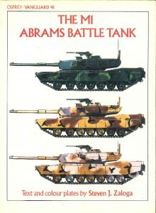
An early production M1Al. Note the absence Commander's Independent Thennal Viewer.
D: : ~.£ -:;~",,:;7.g
base for the
BACK COVER TOP
An M1Al buttoned up and moving cross cowo::r:. :-..: -:i::-: strips on thefront
ofthe turret are for mounting the Mull iple In:eg' ~:.:.; :..o...x~ ::r.g;zgemen t System
(MILES). This system has allowed the usc ;' :':-:;'.i ~--!. ;':'ge vehicles to be
integrated into field maneuvers and U)ilrg.::r-.
BACK COVER BOTTOM
A nice comparative photo of an MIA2 IIg.;',,;;
:~.£ .'. ::..-'. .:
:"'l :r.e photo above.
Abrams Main Battle Tank
M1Al and ;\IL-U
By
Glen Broman
Published by
Darlington Productions, Inc.
P.O, Box 5884
Darlington, Maryland 21034
Copyright 1996. All rights reserved. No portion of this publication may be reproduced or reprinted without the written consent of the publisher. For more information on this and other Darlington Productions publications, write to the address above. Acknowledgements Iwould like to acknowledge and thank Robert Horton and Major David Dodge for their individ ual assistance. I would also like to thank T ACOM, Armament and Chemical Acquisition and Logistics Activity (ACALA), General Dynamics Land Systems Division, and the Maintenance Operations and Proced ures Shop ACALA.
2
Abrams Main Battle Tank
MIAI and MIA2
From the 6th of June 1944 to the 7th of May 1945, American tankers fought the Germans with a mixture of skill and courage. Skill was necessary to get the M4 Sherman into a posi tion on the flanks or rear of the German tanks to achieve a kill with the comparatively weak main gun. Courage was necessary because the 75mm and 88mm main guns of the Tiger and Panther tanks would rip through the armor of the Sherman at long range. The generation of American tankers who sur vived these encounters determined thattheir sons and grandsons would never again fight a foe with a technological edge on the battle field. The fruit of their labor is the M1 series of Main Battle Tanks (MBT), named after General Creighton Abrams, commander of the famous 37th Tank Battalion during WWll. The M1 was built usi ng the princi pIes of Pre-Planned Product Improvements (P3I). The Block I improvements led to the M1A1, the Block II became the M1A2. The turret was designed to accept an increase from the 105mm main gun in the M1 to the 120mm in the M1A1 and M1A2. Armor thickness in creased, a Nuclear, Biological, and Chemical (NBC) overpressure system was added, as well as improvements in fire control and reliability. While the changes from the M1 to the M1A1 were evolutionary, the changes between theM1A1-and the M1A2arerevolu tionary. Although the two tanks are extremely similar, the M1A2 replaces the hard wiring of the M1A1 with Vetronics; two redundant electronic buses, one controls power and the other data. The Inter-Vehicular Information System (lVIS) of the M1A2 digitally links unit vehicles together, passing tactical infor mation and providing a Position/Naviga tion (POS/NAV) system. The Army has already embarked on the next round of im provements. The M1A2 System Enhance ment program (SEP) will take the Abrams series into the next century.
The MIAl The M1 A1 family consists of three variants. The M1A1, the M1A1 Heavy Armor (M1A1HA), and the M1A1 Heavy Armor-
TOP, RIGHT: The Chrysler-developed XMl was the nation's first turbine-powered main battle tank. RlGHT: Vulnerability testing of the XMl 's compart mentalized ammunition.
3
bardment, I had thirty-two left. After twenty minutes in action against the MIs, I had none."
M1A2
Ml Abrams production line, Warren, Michigan .
Common (MIAIHC). The MIAIHA has depleted Uranium armor which improves its ability to withstand kinetic energy pen etration. The MIAIHC has the improved armor and a digital engine control system. The MIAI is distinguishable from the Ml by its 120mm main gun, large bore evacuator, longer turret, and, on most vehicles, a raised circular platform forward of the loader's hatch . It is nearly impossible to distinguish between the different variants of the MIAI family. Most changes are internal. The MIAI family has several different external improvements, however, none of them can be used to identify variants. The MIAI has two different types of tracks. The T-156 solid rubber chevron type and the T-158 with re placeable track pads. This type has been referred to as "Bigfoot" track in the hobby press, although I don't question their sources, I have never heard a tanker refer to it as anything other than T-158 track. The MIA1 also has three different types of wind sensor, two cylindrical types and the "T" top. There are also two types of blow out panels, both types are illustrated in the photos that follow. These different compo nents are not indicative of sub types of the MIAI but seem to reflect when the tank rolled off the production line. The MIAI began replacing the MI in Army units in Europe in the late 1980's. Fielding of the MIA1 in the United States began with the 3rd Armored Cavalry Regi ment and was not completed until Desert Shield. ManyContinental United States (CO NUS)-based units deployed with MIs and conducted their new equipment training in
4
I
Saudi Arabia . U.s. Army transition was completed prior to the start of Desert Storm and the USMC converted some of their units prior to the start of the ground war. The combat record of the MIAI has been covered in great depth in the press and contemporary books by Steve Zaloga, Rick Atkinson, and Tom Clancy. A quote in Ar mor magazine from a captured Iraqi lieu tenant Colonel who was on the receiving end of the MIAI best sums up its combat perfor mance. "When I went into Kuwait I had thirty-nine tanks, after six weeks of air bom
The Ml A2 is externally similar to the MIA 1. The identifying differences are the Commander's Independent Thermal Viewer (CITV) housing forward of the loader's hatch and the simplified Commander's Weapon Station (CWS). The Ml A2 is fitted with the T-158 track. The major differences between the Ml Al and the MIA2 are internal. The technologi cal difference between the two tanks is like the leap between the M60Al and the MI. During a recent exercise at the National Train ing Center (NTC) the Ml A2 was found to be several times more lethal on the battlefield than the Ml AI. The new generation of tank ers who have been raised on computers and Nintendo seem to have little problem adapt ing to the new systems and can operate the MIA2 at peak efficiency. The Gunner's Control and Display Panel (GCDP) links the gunner with the vehicle data bus and provides a Multi-function Dis play (MFD) showing the status of the arma ment system. The Driver's Integrated Display com bines the functions of three analog panels of theMIAI and improvesthetypeand quality of information as well as providing diagnos tics. The CITY is key to the improved capa bility of the Ml A2. The commander can scan the battlefield independent of the gunner or take control of the turret and engage targets
An M1Al with the tank commander's hatch in "protected open," and the loader covering his assigned sector. The crew has used the vehicle tarp to provide additional protection for their duffel bags and gear.
from his position. The Commander's Inde pendent Display (CID) is the interface to all of the vehicle subsystems and the Inter-ve hicular Information System (lVIS). The Ra dio Interface Unit passes the digital informa tion from the IV IS through the new SINCGARS family of frequency-hopping radios to other vehicles in the unit. Addi tional improvements include the POS IN A V inertial guidance system, and im provements in the hull, turret and fire control electronics. The Digital Electronics Control Unit (DECU) controls the AGT 1500 turbine engine and provides status via the data bus. The redesign and simplification of the CWS was very popular with tankcommand ers. The MIA1 CWS provided the capability to fire while buttoned up but it was difficult to use. The Improved MIA2 CWS has better vision and a simplified .50 caliber mount which can only be fired with the T.C.'s hatch open. All of these improvements combine to make the MIA2 one of the most lethal weap ons on the modern battlefield. Probably the most difficult part of a crewman's transition to the MIA2 involves memorizing all of the new acronyms. Fielding of the MIA2 has begun in the United States Army as well as Saudi Arabia and Kuwait. The Army is planning to field 1,079 MIA2sby2003.
Photograph ofan MIA2. The MIA2 weights 68.7 tons combat loaded.
Future Developments The planning for the next Abrams upgrade is already underway. Altemativelycalled Tank 1080 or MIA3, it should begin production around 2003-2004. Planned improvements include upgrades in lethality, survivability, and mobility. The current System Enhance ment Program (SEP) includes the installa tion of improved processors, an under-ar mor auxiliary power unit (APU), a mass memory unit to handle manuals and digital maps, "Force XXI" command and control software, a global positioning sensor, and other improvements.
Camouflage and Markings The Ml Aland Ml A2 come in two basic schemes, the U.S. equivalent of the standard NATO three-color scheme and sand. The NATO scheme consists of a pattern of Black FS 37030, Green FS 34094, and Brown FS 30051. The Sand is FS 30277. The paint is a Chemical Agent Resistant Coating (CARC) and most tanks have a rough traction surface coating applied on the upper surfaces. The tanks are fac tory or depot painted us ing the same pattern with a two inch al lowable devia tion. Because the paint is carcinogenic in its vapor form, crews are not allowed to repaint their vehicles. Markings are pretty sparse, gener ally consisting of a unit designation and a bumper num ber, a Military Load Clas
sification symbol, a name supplied by the crew, and a tactical (rAC) sign or marking such as the type used by Coalition forces in Desert Storm. There are fifty-eight tanks in a tank bat talion. The tanks are numbered with the company letter followed by the platoon num ber and the vehicle number, i.e., A-31 would be the Third Platoon Leader's vehicle of A Company. The Platoon Leader is 1, his wingman is 2, the Platoon Sergeant is 4 and his wingman is 3. The Commander's tank is 66 and the Company Executive Officer (XO) is650r 55, the Operations Officer's (5-3) tank is usually HQ-65, but some carry the bumper number HQ-63. Tank names generally start with the Company letter. Company A would have names like Apache, Abused Kids, and Ani mal House. These names are usually found on the bore evacuator but some units add them to the front of the turret. The only time you will see really color ful markings are on tanks competing in the Canadian Army Trophy (CAT) tank gun nery competition. The infamous "Bill the Cat" decal was a product of CAT com pet i tion marking. Despite the Army's attempt at unifor mity, there is still some variation between units on basic markings. Photographic evi dence is stiU the best method to determine the type of markings a given unit used. NOTE: The term left and right in the photographs refers to the driver's left and right when seated in the driver's hatch with the main gun over the front deck.
5
The leftfr
. '
.
. ,.
ont armor skirt open reveal ing the idler w heel, several roadwheel station s,andthesidesk Irt ' support arms.
Another loook at the compensating 'dl shadows , the track adjust in /" I ,er and, in the g mk on thIs MIAI.
th 'd ------ On the n'ght Sl'de of an MIAI . eller, track ad" wllh the skirt and looking at left is shown the l:tmg,arm,and the first roadwheel arm. of the.adjusting lin:to el To the prIOr to being bolt d' IllustratIOns below how the Idler arm and e mto place (the bolts have :een omItted t~ adjusting link forc/arity)
th~
~lOn
IDLER WHEEL REMOVED FOR CLARITY
6
I
r~;~m:d s~tion.
.
Above and below are illustrations of the torsion bar housing from both sides showing the number of bol ts holding it in place.
Close-up ofan MIA2 roadwheel. The center dust cover is made of an incredibly hard, clear plastic. Lubricant is applied by removing the center bolt ,
The bump stopoverroadwheel station 1 is welded to the side of the hull while the bump stop at station number two is bolted on. The bump stop prevents unrestricted travel of the roadwheel .
On the left side ofan MIA1 with the skirt pulled back, you have a clear view of the return roller, the side skirt arm, the housing cover for the torsion bQr and rotary shock absorber, and the bump stop.
7
The distinctive T-156 track on an MIA1. The front portion of the fender is a rubber strip.
Left drive sprocket of an M1 A2 showing off the T-158 track pads.
The illustrations above and to the left show the lifting tool used to remove the drive sprocket from the hub. Missing on the drawing is the holding pin and SIlfety chain for the upperarm. Theblockthatslides on the upper arm and holds the ring (connected to the lifting hook) should have a pin cen tered in the side section with a small SIlfety chain. The drawing to the left is basically the SIlme except that it does show the hub with the sprocket removed.
A close look at the drive sprocket on an M1A2 . Note the large holes, both for weight reduction and to help throw out mud and debris.
A mud scraper services each drive sprocket.
8
I
An MIA2 with the gun tube in over the rear deck in travel lock.
A look at the component parts of the headlight and guard.
RIGHT: The right front fender and headlightguard on an MIA2. Note the difference fran the headlight guard of the MIAI shown to below.
The right front headlight guard of an MI AI. The black circle with the number "68" is the military load classi
fication.
The front slope of an MIAI. Of note is the good side view Of the headlight guard and the fairly rough weld seam where it attaches to the hull. Also shown to advantage here is the fender torsion baron the far fender and directly below that on the front slope is theelectrical conduit for the headlight wiring. It is relatively flat and runs to just short of where the fran t slope and fender angle meet.
9
The driver's hatch ofan MIAIHA open and locked. Notice the very small and narrow notch in the center of the front slope of the hatch opening . This photo also illustrates the back of the hatch. The small cut-out in the base of the gun mantlet is the opening for the Gunner's Auxiliary Sight (GAS). The driver's hatch lifting mechanism
A EOVE: This photo shows the front fuel filler cap on the left side. You can also clearly see the channel that the driver's hatch seats down into when closed. Also by looking closely in the lower center of the photo you can see the top end of the electrical conduit from the hl!Jld light.
Detail of the center periscope windshield wipers.
The backside of the driver's hatch with the rear guard removed (as well as the hatch stop guard in the center) showing the electrical wiring for the wipers.
Standing on the right side of the tank with the driver's hatch swung into the open position you can see the periscopes and the covers along with the twin wipers on the front block. To the left of the hatch in the photo is the right fuel filler cap . The weld seamson the turret sections, while small are still visible.
10
I
The driver's compartment of an M1A1HA. The large cylinder is part of the back-up Nuclear/Biological/ Chemical (NBC) system. The cylinder itself is painted a forest green, while the due/ing on top is a mustard yellow. The driver's instrument panel (DIP) is on the left of the photo. This panel includes the RPM gauge, speeedometer, fuel gauge, electrical system gauge, fire extinguisher switch, and twelve maintenance system light-emitting diodes .
A look at the entire DIP on this M1Al.
The right side driver's compartment ofan M1A2 . Note the hatch lifting mechanism in the upper center of the photos. Just forward of the mechanism is the control box fur the driver's internal communication system. Behind it is one ofthe fire bottles. Near the bottom is the canvas bag for the night periscopes and on the side wall is the gear selector.
Similar to the photo above, this is the driver 's compart ment of an M1A1HA with the seat in the reclined position for driving.
11
ABOVE LEFT: View ofthe MI A2 Driver's Integrated Display (DID). This display combines the [unctions of the MIAI Driver Alert Panel, Driver's Master Panel, and Driver's Instrument Panel into one display.
ThisMI has the retainer ring on theoutsideof the drive sprocket. After a fair amaunt of experimentation and testing, it was decided that the "training wheels," as they were called, could be eliminated.
LEFT: The driver's control column on an MIA2 . The gear selector is in the center. The center pedal (very bottom of photo) is the brake and the right pedal is the parking brake. The tank is accelerated by twisting the hand grip to the rear. The Dl D can just be seen on the farleft.
An M1A1 with .50 caliber and loader's M240 machine gun mounted. Spare track blocks are mounted on the turret stowage box. This vehicle is equipped with T-158 tracks.
12
Looking down on the back deck of an M1A2. From right to left are the air intake port, the pre-cleaner doors , engine access cover, and battery cover.
RIGHT: On the left side of the tank, the sponson covers are shown. These covers allow access to the crew heating and conditioned air system as well as portions of the NBC system.
-----
._-------With the cover completely removed you can see the maze of tubing, hoses, and boxes. The parts located to the right are for the NBC system and can be seen connecting to the louvered plate just above the armored skirt. The precooler box is immediately inside the louvered plate with the partide separator (rectangular box with numerous small holes) located against the far wall. Other fixtures are for heating, conditioned air, and pressurization systems.
The same as above except with the entire sponson cover lifted and the individual access panels removed.
13
Close-up ofthe louvered port for the NBC overpressure system. The round opening to the extreme left is the crew compartment heater exhaust.
Viewed as if standing on the turret looking towards the back ofthe tank you see the battery compartment on the left side with the starter assemblies and wiring harness to the inside.
An interesting illustration showing the sling device used to lift the grill and engine deck from three poin ts.
The right side of an MIAI. On this side there is a single rectangular sponson box (Note drain plug in left illustration). The sponson boxes used for tool stowage. Located behind it are two ammunition blow-out panels,
14
~o
With the step plate removed, this is the same view of the engine as to the left, shown from opposite sides.
Looking down through the access engine panel located directly behind the turret ring.
The illustrations above and below show more of the general arrangement of the ACT 1500C Turbine engine of the
Ml series MBT.
[
A close-up of the right side grille door mounting.
15
The left rear ofan MIAI showing the grille door mounting hardware. The bustle rack is also mounted on this vehicle as opposed to the M1A2 shown to the right.
The right taillight assembly and protective housing. Note that only the right side has an external wiring harness and protective guard as shown above. The details of the tamight are illustrated below. The black "MOP II" on the sand background is called the bumper number. This particular MIAI was used to train Logistics Assistance Representatives on maintenance procedures at Rock Island Arsenal.
A similar view of the rear, thistimeofan MIA2 painted in an overall sand. The right side grille door is painted flat black. Note the shipping tie-down locations are marked.
Detail of the towing pintle on an MIAI . Note the discoloration of the exhaust grille in the center.
Tow pintle detail.
RIGHT: Theanglebnacket,hinge,and hinge pin for the rearmost side skirt and track fender.
16
RIGHT AND FAR RIGHT: Grenade launchers are located on either side ofthe turret aimed in a frontal arc. The slender box on the right side of the turret just forward of the launcher (right photo) amtains reloads. Note the tent-like protective channels for the electrical cables leading to the launchers.
Antenna mount on the left rear of the turret.
LEFT AND BELOW LEFT: This photo shows the mantlet, the flash suppressor for the M240 coaxial machine gun, and the mounting brackets far gunnery training devices on an M1A2. The lower photo is similar except from the oppo site side and of an M1A1.
A front on look at the mantlet and access panel on an M1 A1. Note the small notch in the mantlet where the gun tube meets, this notch is not present on M1A2 vehicles.
17
The main gun bore evacuator, which causes the propel lant gas to exit the gun tube instead of entering the turret through the breech. The Muzzle Reference Sensor (MRS) and the main gun thermal shroud. The MRS determines the amount of change in the gun tube resulting from uneven heating and cooling. The thermal shroud reduces uneven heating and cooling.
This is an MIAIHA right front turret. The welded numbers are 71S9-U. The "U" denotes the depleted uranium heavy armor. This is the only difference between the MIAIHA and the MIAI, The unit J commanded in Germany stenciled "Heavy Metal" on the sides of the engine compartment to make the identi fication easier until the entire unit was equipped with MIAIHA's.
I ...J }
. ---- -..-~--
This photo illustrates the "T" fixture that secures the front end of the tow cable on the right turret side.
Left side of the MI Al turret with bustle rack. Note folded wind sensor. Also channel fixture for holding the end of the tow cable in place.
18
I
RIGHT: An erect MIAI wind sensor. TIlis is one of three different types used on the MIAI and MIA2 . Note the prominent blow-out panels on the turret top. BELOW: The rear of an MIA2 without a bustle rack and a different style wind sensor.
.r
__ - _ - I
The M1Al turret looking forward.
The M1A2 turret looking forward. The CITV and loader's hatch are closed.
Front view of an M1Al with the commander's hatch in the protected open position. This allows the commander additional visibil ity while still providing protect ion from enemy fire.
An M1A2 looking towards the rear. Notice the different layout of the blow-out pane/so
The commander's weapon station (CW5) and loader's hatch on the M1Al. The M1Al CW5 was universally disliked by tank commanders. The M1A2 CW5 is far simpler, but the .50 caliber cannot be fired from inside the tank. RIGHT ABOVE: A good look at the gunner's primary sight ballistic shield cover on an M1A2 . Thearmored doors are in the open position. Tankers refer to this as the "doghouse. "
RIGHT: This lightly armored cover on an M1A2 houses the connections for the external auxiliary power unit (APU) that will be mounted in the turret bustle rack.
19
Front view of the MIA2 CWS.
, Close-up of the mount for the M2 .50 caliber machine gun on the Ml A2 C WS . The ammuntion box fits in the tray at left. The two handles are locks for the machine gun mount, which has full 360 ' rotation.
LEFr AND LEFr BELOW: The loader's hatch and machine gun mount. Note the protective coverings for the wires and cables behind the hatch.
BELOW: MIAIHA showing offa different style of turret blow-out panels.
BELOW AND BELOW RIGIIT: TheCWS on anMIAIHA. The pins visible in the left photo hold the machine gun in place on the mount.
20
A panoramic view of the forward section of an MIA2. In the left center (with the cable and plug hanging down) is the SINCCARS radio. Above that is the Commander's Independent Viewer. In the upper right is the Commander's Integrated Display (CID). Below the CID panel with the grid displayed is the Cunner's Control and Display Panel (CCDP) . RIGHT: Another view of the looder's position, show
ing the loader's shoulder guard. The base of the CITV is in the upper center.
The gunner's position on an MIA2 . The sight on the left is the Cunner's Auxiliary Sight (CAS), the Cunner's Primary Sight (CPS) is in the center, and the CCDP is to the right. The pad in the centerprotects the gunner's chest.
MIA2 loader's position. The loader's panel is to the left. The box to the right shows the main gun status (safe/armed) and has switches for turret power and blowers.
RIGHT: MIA2 tank commander's position with the TC shoulder and knee guards erected.
21
The M1A2 TC position with the guards lowered. The sight in the foreground is the Gunner's Primary Sight Extension (GPSE). This aIlows the TC to see exactly what the gunner is seeing. In the center of the photo is the Commander's Control Handle Assembly (CCHA), unofficially caIled the TC override or "joystick." The CCHA has a palm switch, trigger, Field of View (FOV) and target designate buttons, and a range/stadia reticle switch.
Right side of the main gun showing the mount for the • coaxial M240 machine gun . The L-shaped handle below the GPS is the emergency firing device ("master blaster"). The handle is painted red.
LEFT: The breech ofthe M256120mm main gun in the M1A2. The loading ammunition tray is in the firing position, it will deflect the stub base from the cartridge down into a basket on the floor when the main gun is fired.
The left side of the main gun of an M1A2 . The vertical box (behind the loader's shoulder guard) is the ammu nition box for the coaxial machine gun . . The oval "windows" allow the loader to check remaining ammo at a glance. .
The MIA2loader's position with the hatch closed. The hatch has a mounting bracket for a periscope which gives the loader some visibility when buttoned up. The upright metal plate in the center of the photo is the loader 's knee switch which operates the ready ammuni tion rack armored door. The switch is in the stowed position. The small box above the loader's control panel is a fire sensor. The cover below the control panel protects the radio and intercom system control panel (called the "1780").
22
LEFT: The TC's position in an M1A1 showing the semi-ready ammunition rack door. Later models of the MlAl and MlAlHA had a two round rack added to this side to increase the number ofrounds from 40 t042. This rack is standard on A2 'so The commander's curtain assembly is normally mounted here.
Right side of the MlAl breech and gunner's position. The firing solenoid for the coaxial machine gun is in the center of the picture.
LEFT: Thegunner'spositiononanMlA1. Thesquare box is the Computer Control Panel (CCP). The caver is closed and the gunner's chest protector is stowed.
M1Alloader's position showing the Turret Networks Box (TNB) on the lower right.
LEFT: MlAlloader's position. The smaIl box in the center is part of the intercom and radio system. The crew plug their Combat Vehicle Crewman (CVC) hel mets into these. Crews call them ''lack boxes. "
23